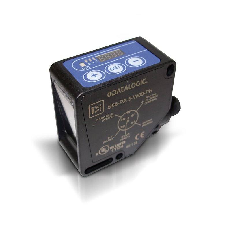
The Datalogic/Datasensing S65-W is an advanced contrast (register-mark) sensor housed in a 50x50x25 mm ABS/PMMA midi case with wide-spectrum white-LED emission and a 3x1 mm light spot at a 19 mm nominal sensing distance. It delivers high 12-bit resolution and 30 kHz switching frequency (0.017 ms response), with PNP or NPN light/dark-selectable outputs and an RS485 serial interface for setup. It runs on 10-30 VDC via an M12 8-pole connector, carries IP67 protection, and uses a 4-digit display plus three pushbuttons (or external teach) for configuration.
Brand
Datalogic / Datasensing
Sensor type
Contrast / colour mark sensor
Sensing method
contrast mark detection (radial 90 degree optics) - not 'diffuse'
Light source
White LED (wide-spectrum emission)
Range / distance
20 mm nominal sensing distance (3x1 mm spot at 19 mm)
The Datalogic/Datasensing S65-W (S65-PA-5-W09) is a contrast/colour mark sensor whose job is to resolve the difference in remission between a printed register mark and its background and turn it into a fast switching signal. It uses a wide-spectrum white LED so it can read neutral grey marks and a broad range of coloured targets, with the optics arranged as a radial 90-degree head that projects a 3x1 mm light spot at a 19 mm nominal sensing distance (20 mm rated). That small, well-defined rectangular spot is the key working parameter: in practice you align the long (3 mm) axis of the spot across the direction of web travel so each mark passes through it edge-on, maximising the contrast transition the sensor sees as a register mark enters and leaves the field. As a contrast/colour mark sensor it discriminates marks by their relative remission/contrast against the local background, taught on the running material, rather than reporting an absolute colour measurement.
Speed is where this part earns its place on a print or packaging line. It switches at up to 30 kHz with a 0.017 ms response time, so it can register marks on fast-moving web without smearing the edge, and the high 12-bit internal resolution gives fine gradation for separating low-contrast marks from busy backgrounds. The output is a clean digital switch (NPN on this variant, with a PNP variant available) that is light/dark selectable, so it is wired as a trigger or registration signal into a drive, cutter, labeller or PLC rather than as an analogue measurement. An RS485 serial interface is provided for setup, and the onboard 4-digit display plus three pushbuttons (or an external teach line) let an installer teach the mark on the actual product without a PC. In practice you teach the sensor on the print, choose light-on or dark-on switching to match your mark/background polarity, and feed the output edge to the registration controller.
The mechanical and electrical envelope suits standard converting and packaging hardware. It lives in a 50x50x25 mm midi case (ABS body with a PMMA active head and lens), runs on 10-30 VDC, and connects through an 8-pole M12 plug that carries power, the switching output, the teach input and the RS485 line. IP67 sealing and a -10 to +55 C operating range make it appropriate for typical print-shop and packaging-machine environments, though the plastic ABS/PMMA construction means it is not intended for high-pressure washdown or aggressive chemical exposure. The fixed ~19 mm working distance and small spot mean web flutter must be controlled mechanically so the mark stays within the spot.
Best for
Print-register/registration control on rotogravure, flexo or offset web presses, reading repeating register marks to keep colour stations and the web in phase
Cut-to-mark and seal-to-mark control on form-fill-seal, flow-wrap and bag-making machines, triggering the knife or sealing jaw off a printed eye-mark
Label and pouch registration on packaging lines, detecting print marks to index labellers or pouch-feed mechanisms
Detecting neutral grey or coloured register marks on busy printed backgrounds where a plain photoelectric sensor would lack contrast discrimination
Phase/position feedback to a PLC or drive at high line speeds where the 30 kHz switching and 0.017 ms response avoid missed or late marks
Selection notes
This is a contrast/colour mark sensor, not an analogue measurement or colour-spectroscopy device: its useful output is a digital switch (NPN, L/D selectable here; PNP variant available), so design the registration controller or PLC input around an edge trigger, not a continuous value.
Mount for the fixed geometry: the 3x1 mm spot is specified at 19 mm (20 mm nominal sensing distance), so set the standoff accordingly and control web flutter so the mark stays inside the small spot.
Orient the spot relative to the mark: align the 3 mm long axis across the direction of travel so each mark produces a sharp contrast transition; this matters more than absolute distance for reliable triggering.
Confirm interface and wiring: it uses an 8-pole M12 connector with RS485 for setup and an external teach input, on 10-30 VDC; budget the extra poles versus a simple 3-wire photoelectric and verify your controller can supply the teach/RS485 lines if used.
Check the environment: IP67 and -10 to +55 C with an ABS/PMMA housing suit print and packaging machines but not high-pressure washdown or chemically aggressive zones; size the supply at 10-30 VDC.
Specifications: General
Brand
Datalogic / Datasensing
Sensor type
Contrast / colour mark sensor
Specifications: Performance
Range / distance
20 mm nominal sensing distance (3x1 mm spot at 19 mm)
Response time
0.017 ms (at 30 kHz)
Switching frequency
30 kHz (30000 Hz)
Resolution
High 12-bit resolution
Specifications: Interface
Communication
RS485 serial interface
Connection
M12 plug, 8-pole
Specifications: Electrical
Supply voltage
10...30 VDC
Specifications: Environment
Operating temperature
-10 C ... +55 C
IP rating
IP67
Specifications: Sensing
Sensing method
contrast mark detection (radial 90 degree optics) - not 'diffuse'
Light source
White LED (wide-spectrum emission)
Specifications: Output
Output type
NPN L/D selectable (PNP variant also available)
Specifications: Mechanical
Housing material
Plastic - ABS body / PMMA active head and lens
Dimensions
50 x 50 x 25 mm (midi case)
Applications this camera is commonly selected for. Open one to see the full recommended hardware and approach.
1. Install the IMPACT Software Suite and connect the camera
Install the IMPACT Software Suite on your PC, which provides both the configuration/viewer tools and the SDK. For a GigE Vision model (E100, M or U series), connect it to a dedicated NIC and, for USB3 models, use a certified USB3 cable and port. Power the camera and confirm it enumerates.
2. Bring the camera online and verify the link
For GigE Vision, put the camera and the host NIC on the same subnet (a static IP on the camera matching the NIC range is the most reliable starting point); for USB3, confirm the device is recognized. Open the IMPACT viewer/device tool, discover the camera, and verify a stable connection before streaming. Enabling jumbo frames on the NIC helps GigE throughput.
3. Set exposure, gain and trigger, then grab a first image
In the IMPACT tools, start a live stream and adjust exposure and gain until the image is well-lit without saturation; set white balance on color models. Begin in free-run (continuous) mode to confirm imaging, then switch to hardware or software trigger as your application requires. Capture and save a reference image once the scene looks correct.
4. Build a vision tool or move to the SDK/API
Use the IMPACT point-and-click vision tools to assemble an inspection, or use the IMPACT SDK to access the camera and results programmatically and feed them into your HMI/PLC application. As these are GenICam/GenTL-compliant devices, you can alternatively drive them from any GenICam-compliant third-party vision library if your pipeline standardizes on one.
5. Route the stable feed to deep-learning inspection (optional)
Once you have a stable, repeatable image, the feed can be sent to a deep-learning inspection platform such as Rosepetal for defect detection or classification tasks that go beyond rule-based tooling. Keep lighting, optics and trigger timing fixed so the images reaching the model stay consistent.
Frequently asked questions
It is a contrast/colour mark sensor with a wide-spectrum white LED. It discriminates marks by their contrast/remission against the local background rather than reporting an absolute colour value, which lets it read neutral grey and a range of coloured marks once taught on the running material.
The nominal sensing distance is 20 mm, and at a 19 mm working distance the white-LED spot is 3 x 1 mm. The mark must pass through this small rectangular spot, so the working standoff and web position need to be controlled.
It switches at up to 30 kHz with a 0.017 ms response time and high 12-bit internal resolution, so it is designed to register marks on fast-moving web and packaging lines without smearing the mark edge.
The output is a light/dark-selectable digital switch, NPN on this variant (a PNP version is also available). It runs on 10-30 VDC and connects via an 8-pole M12 plug, which also carries the RS485 setup interface and the teach line.
You can teach the mark directly on the sensor using its 4-digit display and three pushbuttons, or via an external teach input; an RS485 serial interface is available for setup. You also select light-on or dark-on switching to match your mark-versus-background polarity.
It carries IP67 protection and operates from -10 to +55 C, suiting typical print and packaging machinery. However, the housing is ABS with a PMMA head and lens, so it is not intended for high-pressure washdown or aggressive chemical exposure.