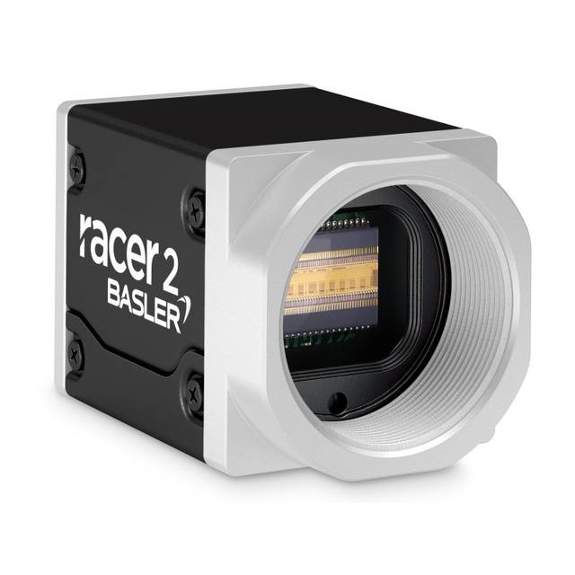
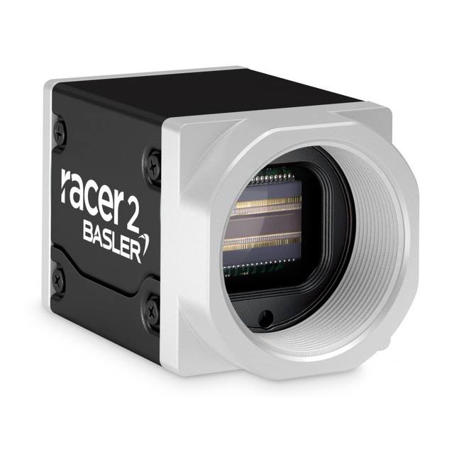
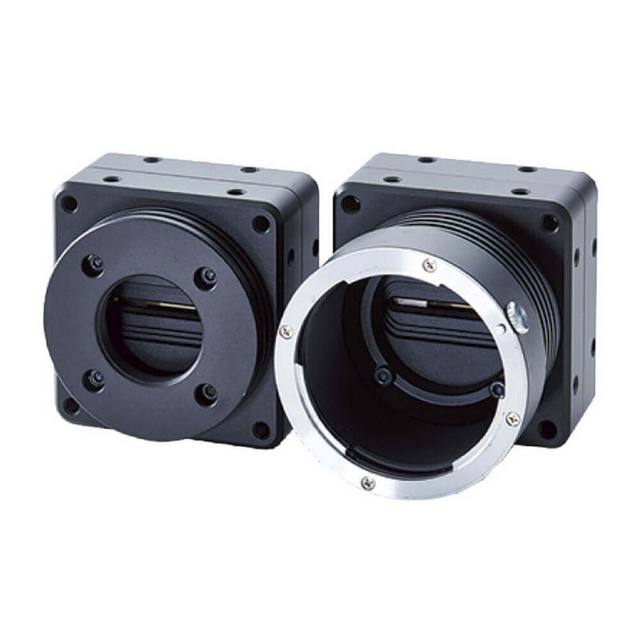
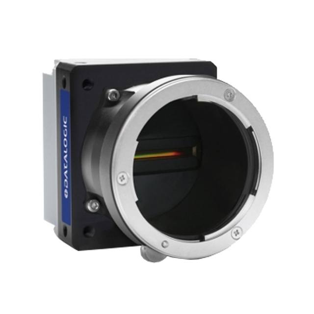
Line scan vision exists to solve a problem that area-scan cameras handle badly: inspecting a surface that is continuous, very wide, or never stops moving. Instead of capturing discrete 2D frames, a line scan camera reads a single row of pixels thousands of times per second and stitches those rows into one seamless image as the material passes beneath it. The result is an effectively unlimited image length and a resolution across the width that no single matrix sensor can match.
That capability comes with a strict condition: the image is only correct if every line is captured in lockstep with the material's true motion. Get the synchronisation, the lighting and the data path right and line scan delivers uniform, full-width inspection of webs, sheets, cylinders and conveyed product at production speed. Get any one of them wrong and the image stretches, compresses or smears, and no amount of software can recover the detail that was never sampled cleanly. This page frames the engineering decisions behind a reliable line scan station and explains why the recommended hardware, line scan cameras, encoders, bar/linear lights and frame grabbers, fits the job.
When line scan is the right answer
Reach for line scan when the part is continuous or far wider than it is tall, when it moves without stopping, or when the across-width resolution you need is simply too high for an area-scan sensor to cover in one frame. Printed and coated webs, paper and film, textiles, metal strip and foil, extruded or rolled product, glass, wood panels and rotating cylindrical parts are the classic cases. In each, the material supplies the second image dimension by moving, so the camera only ever has to be as wide as the product, not as long.
The defining advantage is resolution across the full width with no tiling artefacts. A 4k, 8k or 16k line sensor places thousands of pixels across the web in a single uninterrupted line, so a fine scratch, a missing print feature or an edge defect resolves the same whether it sits at the centre or the edge. Building the equivalent coverage from several area-scan cameras introduces seams, perspective differences and calibration headaches that line scan avoids by construction. The trade is that line scan demands more discipline in motion control, lighting and bandwidth than a single triggered area camera, which is exactly why these systems are usually specified as an integrated whole rather than part by part.
- Continuous webs and sheets: paper, film, foil, textiles, nonwovens, coatings.
- Wide rigid product: metal strip, glass, wood panels, laminates.
- Cylindrical and rotating parts imaged by unrolling the surface.
- Any case where full-width fine detail exceeds what one area sensor can capture.
Encoder synchronisation: the line that makes or breaks the image
A line scan image is geometrically correct only when each captured line corresponds to a fixed increment of material travel. If you trigger lines on a fixed internal clock instead, any variation in conveyor or web speed stretches and compresses the image along the direction of travel, distorting measurements and defect shapes. The fix is to drive the camera's line trigger from a rotary or linear encoder coupled to the actual transport, so one encoder pulse equals one line regardless of how the speed fluctuates. This is the single most important design decision in a line scan system.
In practice the encoder output is fed to the camera or frame grabber, often through a divider or multiplier, so that the line rate matches the desired sampling pitch in the travel direction and produces square pixels relative to the across-width pixel size. Slip between the encoder and the material is the enemy: a measuring wheel that skids on a glossy web, backlash in a coupling, or an encoder reading a driven roller rather than the web itself all reintroduce the distortion you installed the encoder to remove. The encoder must read true material motion, with enough resolution that its pulse pitch is finer than the smallest defect you intend to resolve.
Synchronisation also has to respect the camera's maximum line rate. As line speed rises, the time available to expose each line shrinks, which couples the encoder and motion decisions directly to lighting intensity and to sensor sensitivity. Sizing the encoder resolution, the maximum web speed and the camera's line rate together, rather than in isolation, is what keeps the system from running out of headroom on the fastest product.
Lighting: intense, uniform and aimed at one line
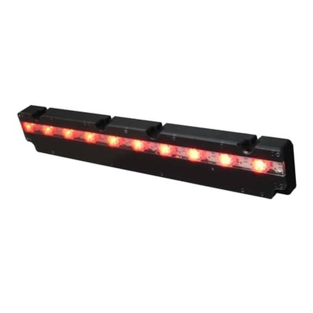
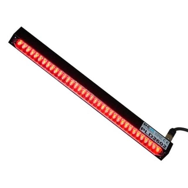
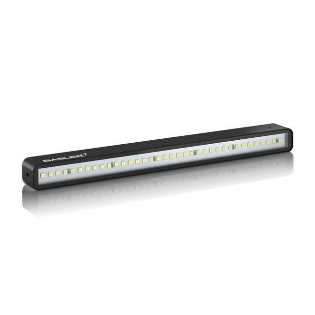
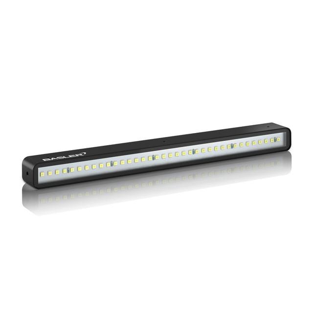
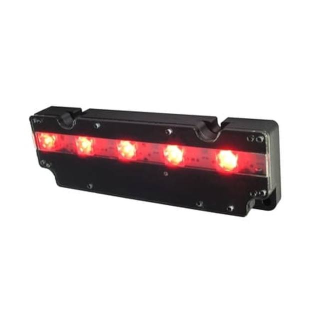
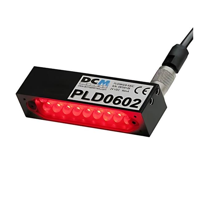
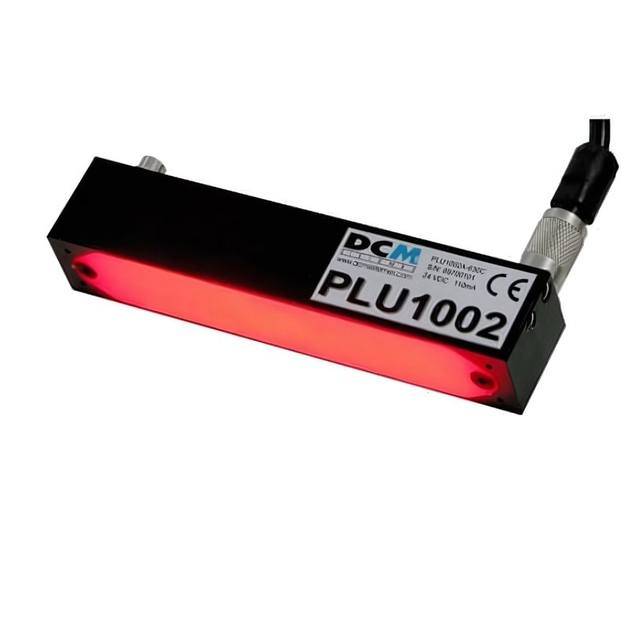
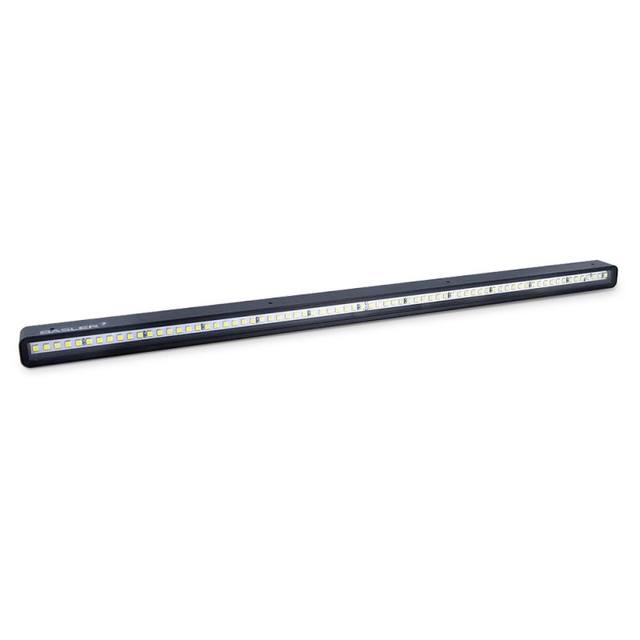
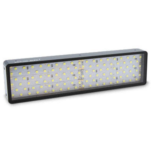
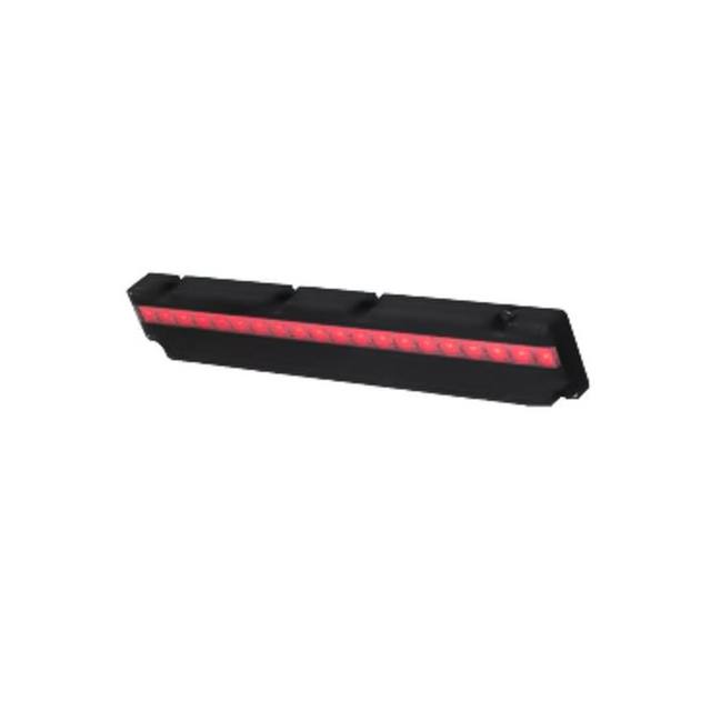
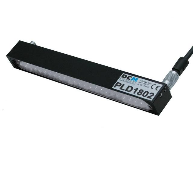
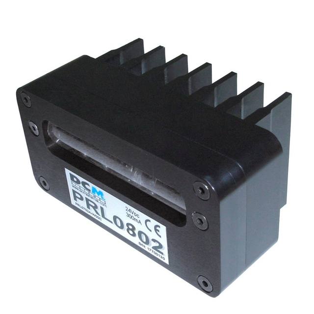
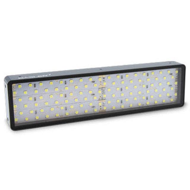
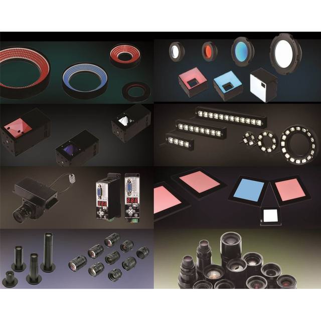
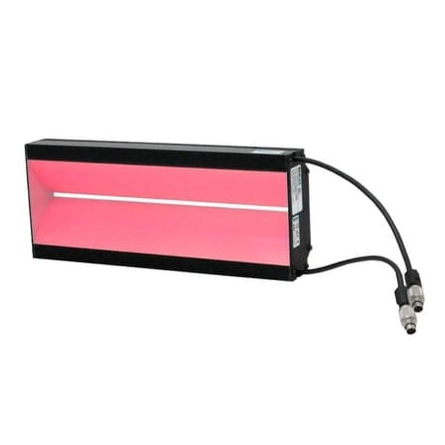
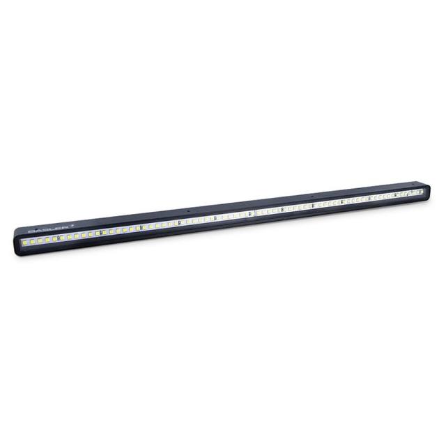
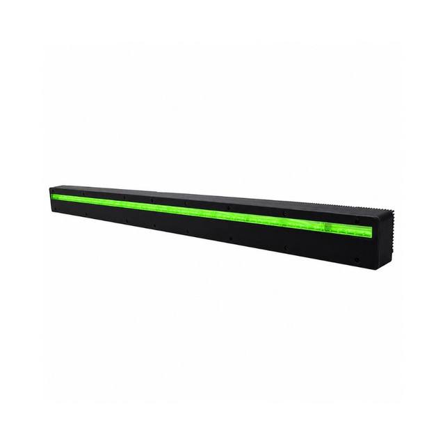
Line scan concentrates the entire image into a single narrow row, so all the light a frame ever receives must fall on that one line during a very short per-line exposure. This makes line scan far more light-hungry than area-scan imaging and rules out diffuse general illumination. The right source is a high-intensity bar or linear light focused precisely on the scan line, delivering both the brightness short exposures demand and uniform irradiance across the full width so that response does not roll off at the edges of the field.
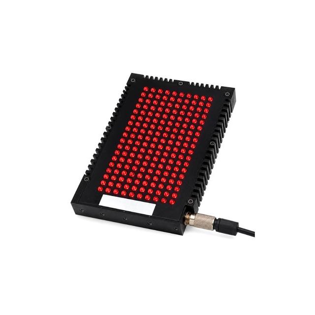
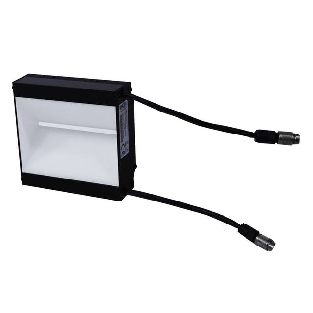
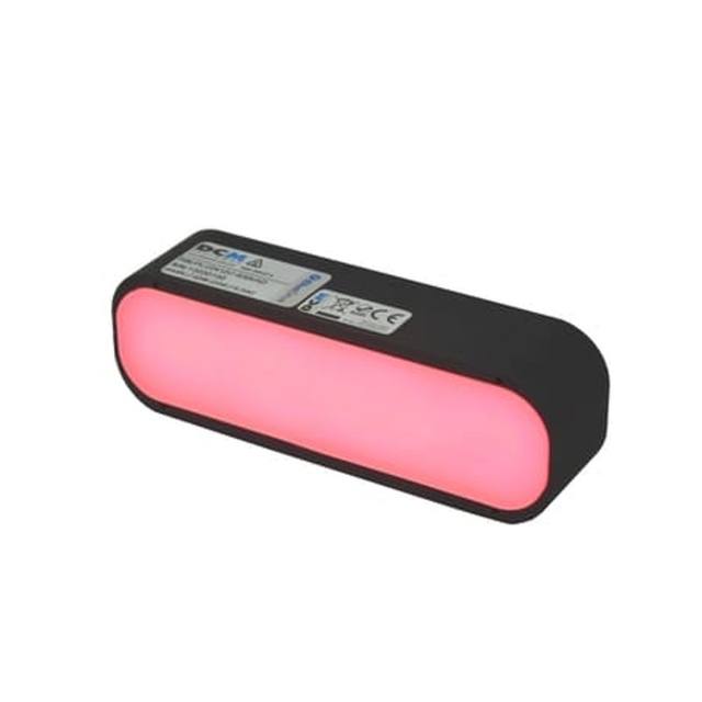
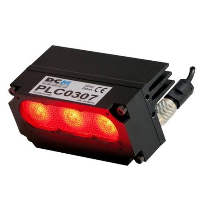
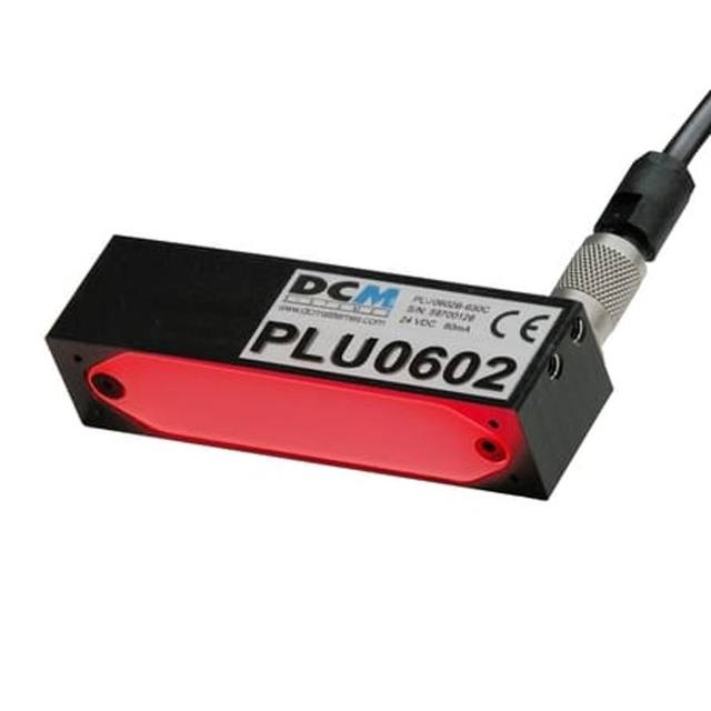
Geometry still does the work of revealing the defect. Bright-field bar lighting suits print, contrast and general surface reading; a low-angle or dark-field bar grazes the surface to throw scratches, embossing and topographic defects into sharp relief; a backlight or transmitted line is used for edges, holes and translucent web defects. Because the lit region is so narrow, alignment is unforgiving, the light, the lens and the sensor line must be co-registered and held there mechanically against vibration and thermal drift. Lighting specialists such as DCM Sistemes supply line-geometry sources in the relevant intensities, and pairing the geometry to the specific defect mechanism usually matters more to detection than adding raw camera resolution.
Stability over time is the quiet requirement. A web inspected for hours needs illumination that does not droop as LEDs warm, so thermally managed, optionally strobed and feedback-regulated bar lights earn their place. Flat-field correction in the camera or grabber compensates for residual non-uniformity and lens vignetting, but it can only correct a stable starting point, not a light that wanders.
Cameras, interface and frame grabbers
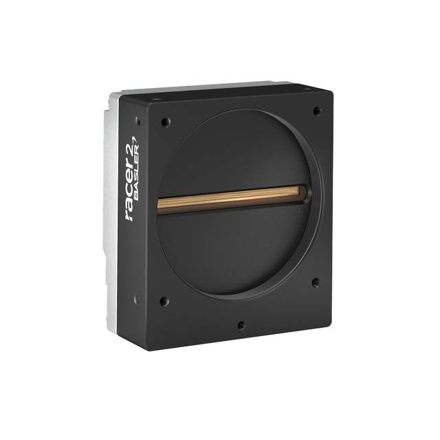
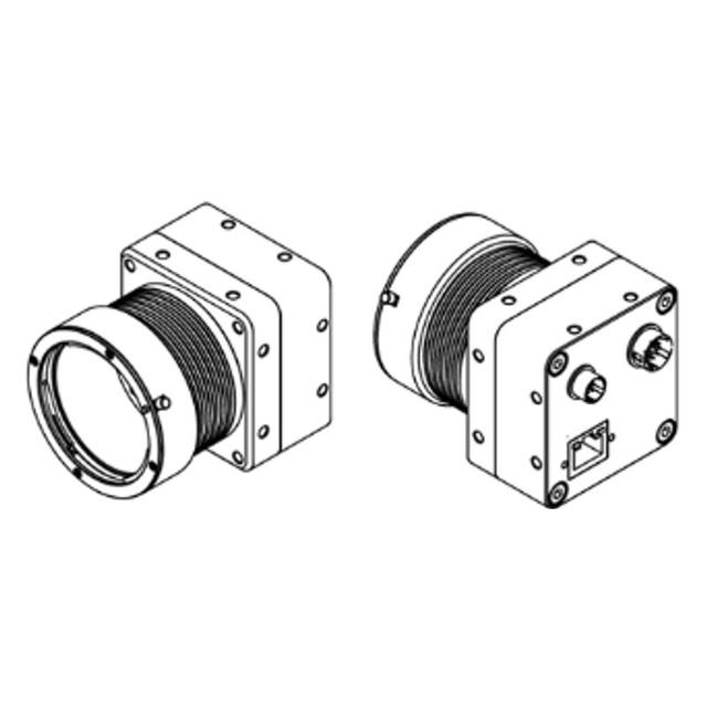
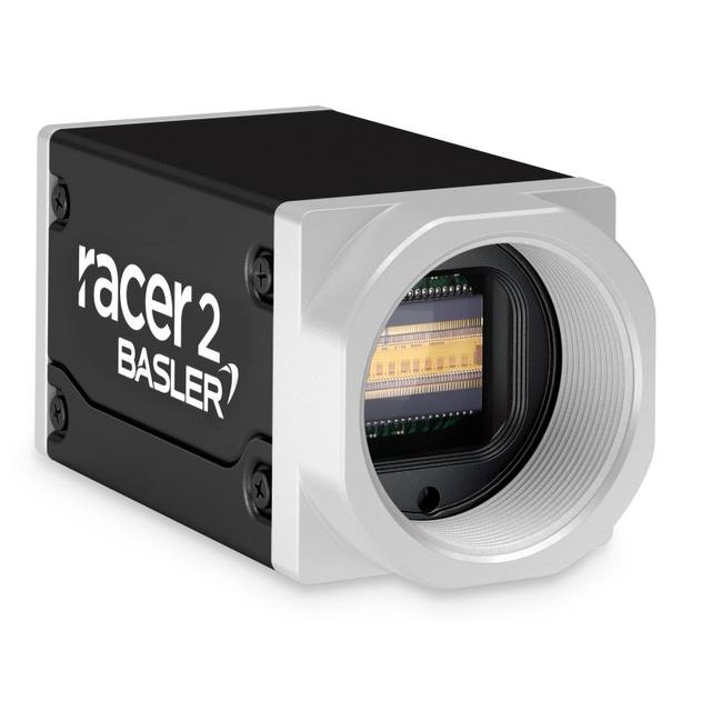
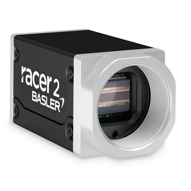
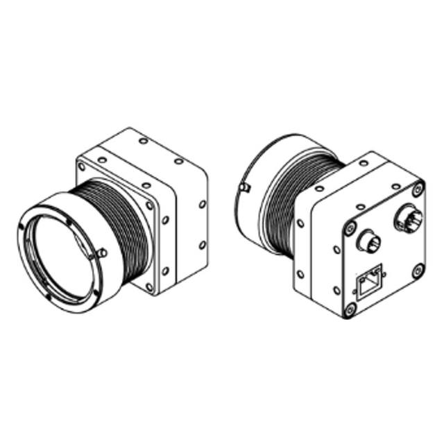
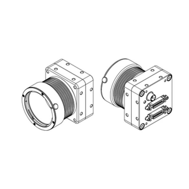
A line scan station produces a relentless, gap-free pixel stream: line width in pixels multiplied by line rate, with no inter-frame pause to absorb bursts. An 8k sensor running tens of kilohertz of line rate easily reaches data rates that exceed what GigE Vision or USB3 Vision can sustain, which is why high-performance line scan is typically built on CoaXPress with a frame grabber in the host PC. The grabber terminates the high-speed link, accepts the encoder signal to clock the lines, performs flat-field correction and DMA-transfers the assembled image into memory deterministically, isolating the inspection software from the timing-critical capture. Slower or narrower applications can run on GigE line scan cameras where the bandwidth budget allows, but the frame grabber path is what unlocks the fastest, widest systems.
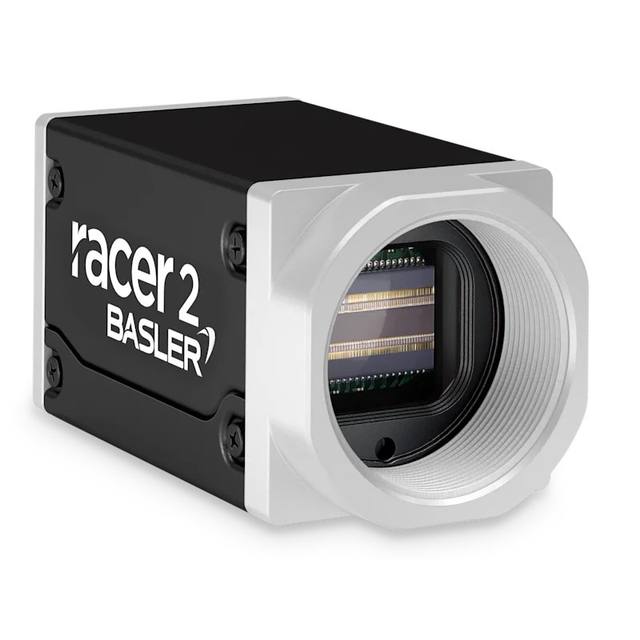
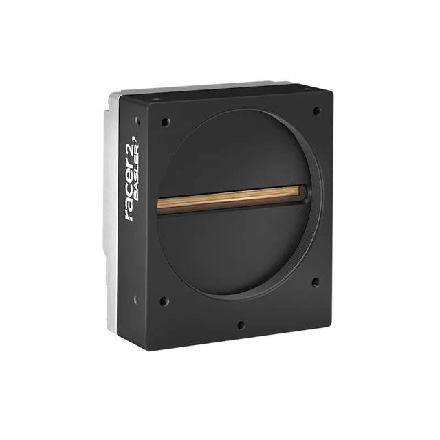
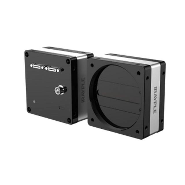
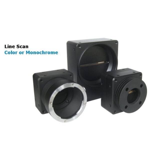
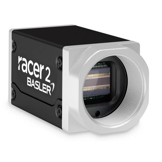
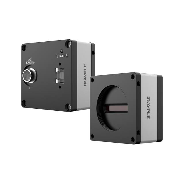
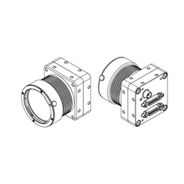
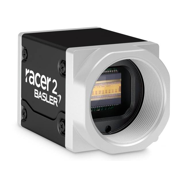
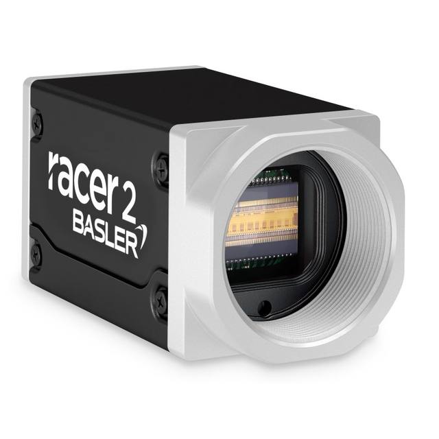
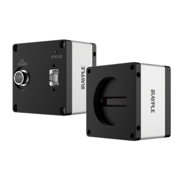
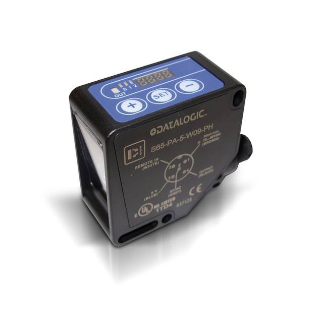
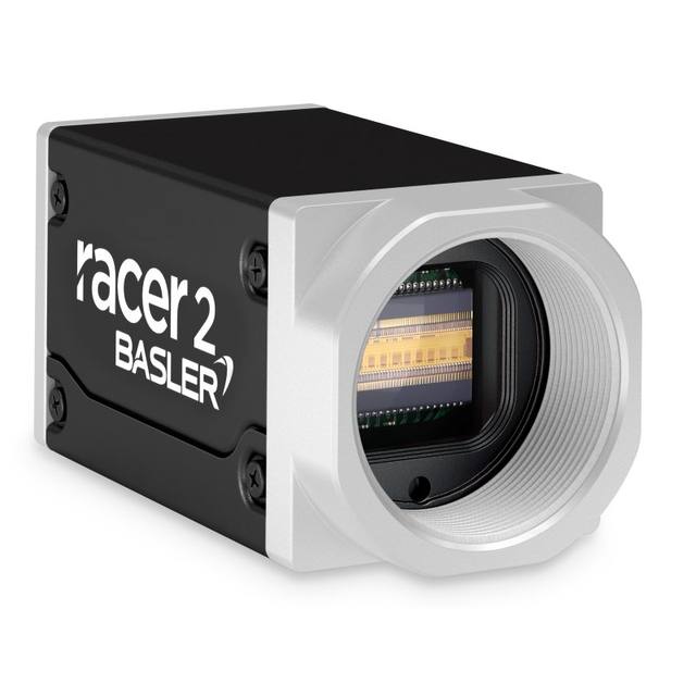
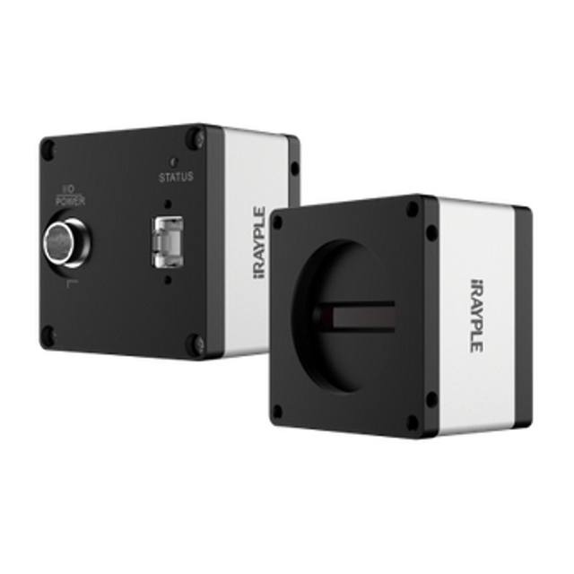
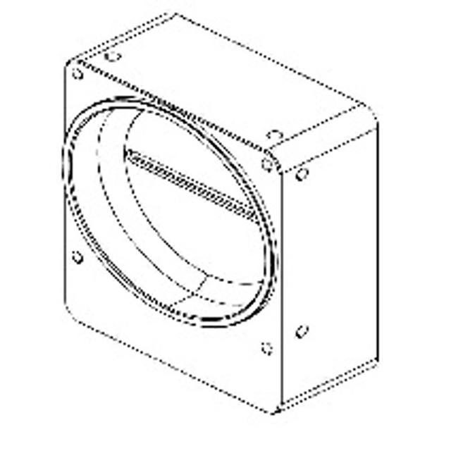
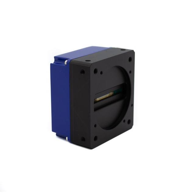
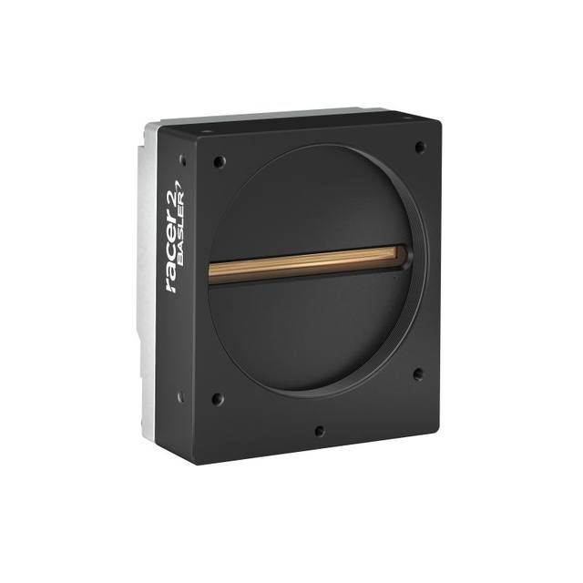
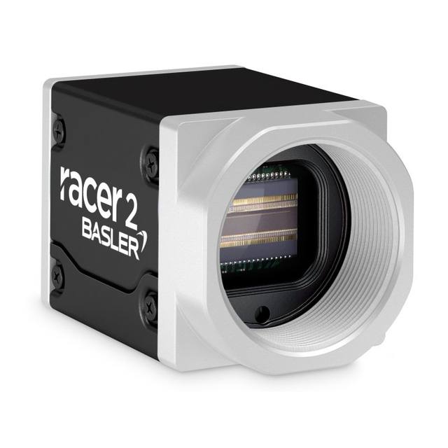
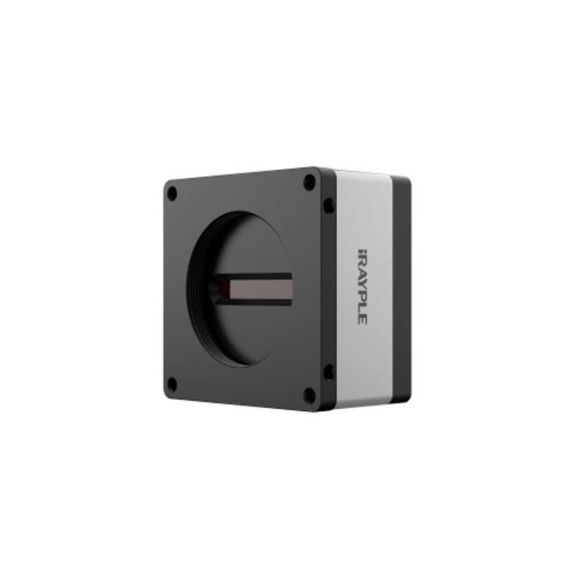
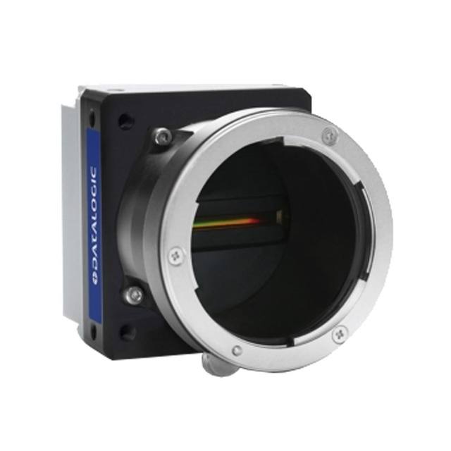
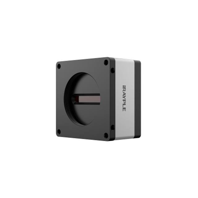
Choose the sensor around the across-width specification first: divide the inspected width by the smallest defect size and target roughly three to five pixels across that feature to fix the pixel count, which points to a 2k, 4k, 8k or 16k line camera. Monochrome sensors give the best sensitivity and resolution for most defect and measurement tasks; colour line scan (often trilinear or Bayer-line) is reserved for genuine colour verification. The catalogue brands, Basler, iRAYPLE and Omron/Sentech (STC), offer line scan cameras and the matching CoaXPress or GigE interfaces, while Datalogic/Datasensing covers code-reading and detection where that overlaps the line.
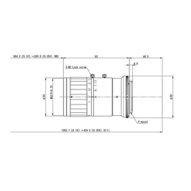
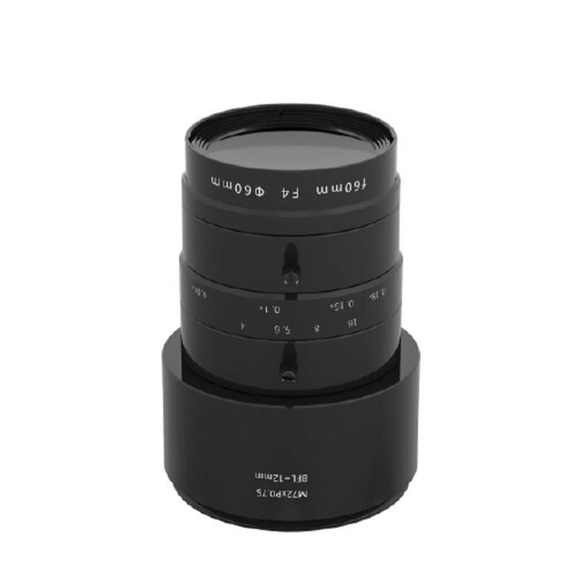
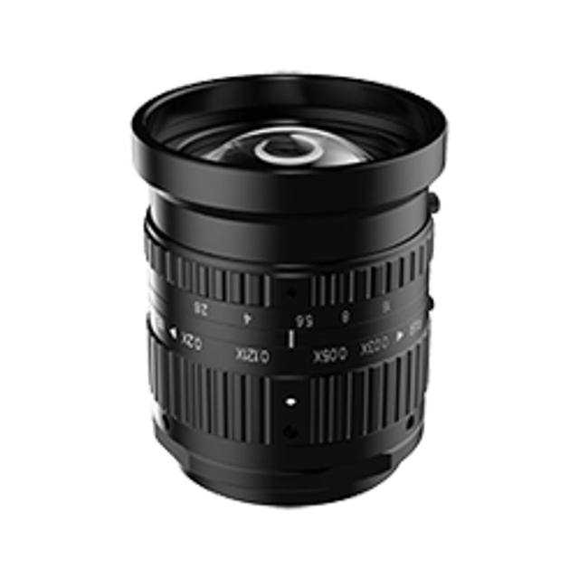
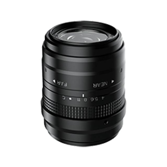
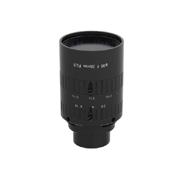
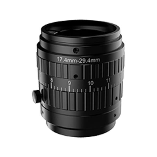
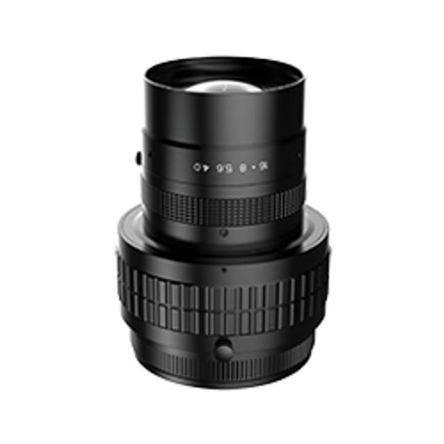
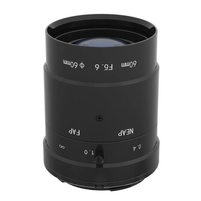
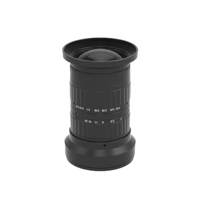
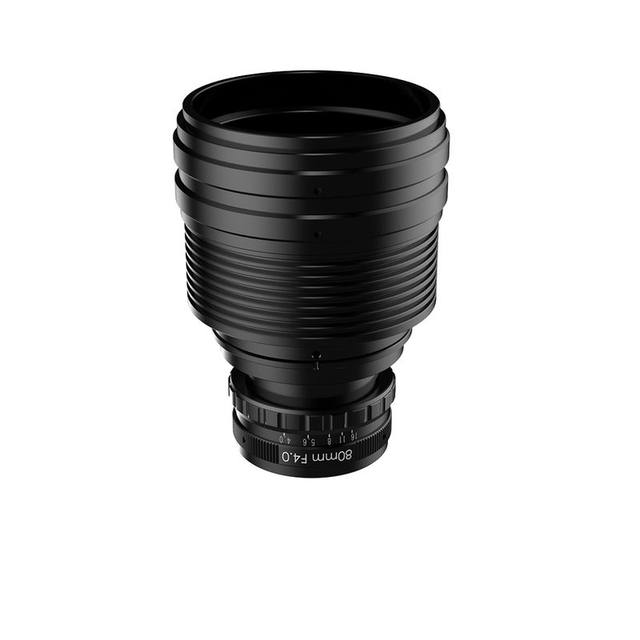
Treat the camera, lens, link and grabber as one budget. The lens must cover the long line format and resolve finer than the sensor's pixel pitch across the entire width, which for wide sensors pushes toward larger-format, high-resolution optics. The interface must clear the peak pixel rate with margin so the stream never stalls. And the grabber's I/O must handle encoder input, light strobe control and PLC handshaking so that motion, illumination and capture stay phase-locked at full speed.
Putting the system together
A dependable line scan system is the product of four decisions taken together rather than in sequence. Start from the across-width detail requirement to size the sensor and lens. Set the maximum web speed and the target travel-direction pixel pitch, which together with the encoder resolution define the line rate the camera must reach. Size the bar light to deliver uniform intensity at the resulting per-line exposure. Then choose the interface and frame grabber to carry the peak pixel stream with margin and to clock everything from the encoder. Each choice constrains the others, so changing the web speed or the defect size late in the design usually forces a re-spin of the lighting and the data path.
This interdependence is why line scan is best validated as a complete imaging chain on representative material before committing the line. The most common failures, geometric distortion from encoder slip, edge fall-off from non-uniform lighting, and dropped lines from an under-provisioned link, only reveal themselves under real speed, real product and real vibration. A controlled feasibility trial that reproduces those conditions de-risks the build far more effectively than matching spec sheets.