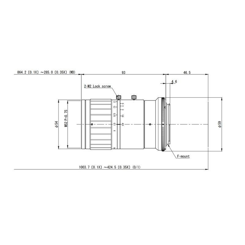
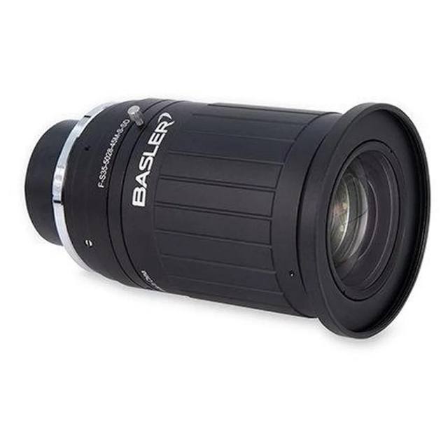
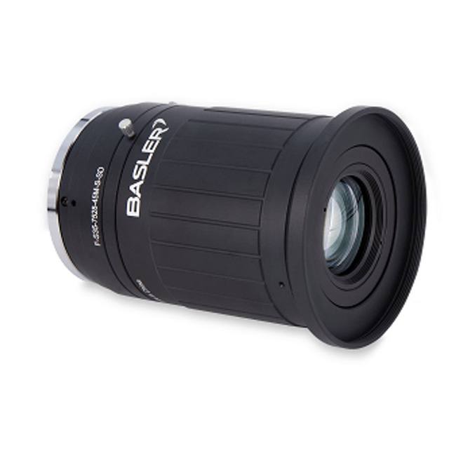
The VS-L8540/M42-10 is a high-resolution large-format macro lens with an 85 mm focal length (84.03 mm actual) and M42 thread mount, covering a φ50 mm image circle suitable for 1.8-inch sensors. It offers a magnification range of 0.1× to 0.35× with working distances spanning 285 mm (at 0.35×) to 864 mm (at 0.1×), and an aperture range of F4.0–F16. The optical design delivers 0.00% TV distortion and is matched to Omron FH-S 12 MP camera platforms; the lens body measures φ59 mm (max) × 93 mm with an M52 P=0.75 filter thread and 46.5 mm flange-back distance.
The VS-L8540/M42-10 is an 85 mm (84.03 mm actual focal length) large-format macro lens built around an M42 thread mount and engineered specifically to cover Omron's FH-S 12 MP line-scan camera platform. Its φ50 mm image circle is the defining specification for installers: this exceeds the diagonal of a 1.8-inch sensor format, ensuring the full detector width is illuminated without vignetting even at the edges of a wide line-scan array. The aperture runs from F4.0 to F16, and the 12 MP optical resolution rating means the optics resolve detail at a pixel pitch consistent with the FH-S*12 sensor — there is no optical bottleneck limiting the camera's native resolving power. At 350 g and φ59 mm × 93 mm body dimensions, the lens is compact enough for integration into tight conveyor headers or gantry-mounted inspection stations, and the M52 P=0.75 filter thread accepts standard bandpass or polarising filters for contrast enhancement.
The working-distance envelope — 285 mm at 0.35× magnification down to 864 mm at 0.1× — gives system designers meaningful flexibility in stand-off selection without changing optics. A 285 mm working distance at 0.35× produces a field of view roughly 3× the sensor width, appropriate for inspecting components whose width is approximately one-third of the sensor's active area width. Extending to 864 mm at 0.1× maps a much wider scene onto the sensor, suitable for web or panel inspection where the camera is mounted far above the product surface. The 46.5 mm flange-back distance is the critical mechanical parameter for integrating with the M42 mount on FH-S cameras; no intermediate adapter ring is required, and the direct thread engagement maintains repeatable parfocal positioning across temperature cycles. Installers should note that the telecentric specification is listed as No — this is an entocentric design, meaning magnification and scale will shift with any axial movement of the subject. Height variation in the inspected object will introduce scale error, so conveyor planarity and part-holding fixtures are important system-level design variables.
The 0.00% TV distortion figure is the headline optical performance claim for dimensional measurement applications. TV distortion is measured across the full image circle using a standard grid target, and a reported value of 0.00% means the lens introduces no measurable rectilinear error at the sensor — straight lines in the scene map to straight lines in the image without barrel or pincushion deviation. For production line gauging — measuring PCB land pitch, connector pin spacing, or film-coated panel feature width — this means software calibration corrections for lens geometry are not required, and measurement uncertainty derives from pixel resolution and alignment rather than optical distortion. Paired with the FH-S 12 MP platform and Omron's FH vision software, the lens supports sub-pixel edge detection and multi-point dimensional checks without polynomial distortion correction overhead.
Best for
Line-scan surface and web inspection where the φ50 mm image circle and 0.00% TV distortion enable accurate, repeatable full-width imaging without vignetting or geometric error across the 285–864 mm working distance range.
Dimensional gauging of discrete components — PCB, connector, or electronic assembly features — in the 285–864 mm working distance range where the entocentric design at a fixed, controlled stand-off gives high-resolution field coverage and distortion-free measurement.
OCR/OCV and traceability code reading on pharmaceutical blisters, battery cells, or automotive labels where character-level resolution from the 12 MP-matched optics and the long working distance envelope allow label and direct-part-mark reading without lens changes across product changeovers.
High-resolution defect inspection on metal, semiconductor, or battery electrode surfaces where F4.0 maximum aperture and well-corrected large-format optics deliver sharp contrast from diffuse or structured illumination setups positioned outside the minimum 285 mm working distance.
Packaging and carton print inspection on moving lines where the 85 mm focal length's narrow angle of view reduces perspective error across the web width, and the 0.00% TV distortion ensures printed registration marks, barcodes, and lot codes are read accurately at the image edges.
Selection notes
Image circle and sensor format compatibility: the φ50 mm image circle is sized for up to 1.8-inch format sensors. Verify the exact sensor diagonal of your FH-S camera variant before mounting — using this lens with a smaller sensor is harmless but wastes the optical field; using it with a larger sensor will introduce corner vignetting.
Working distance and magnification are coupled in this fixed-focal-length lens: the 0.35× to 0.1× magnification range maps directly to 285 mm to 864 mm stand-off. Size your field of view by computing the required magnification (sensor width / object width) and confirm the resulting working distance fits the mechanical envelope of your installation before designing the frame.
This lens is an entocentric (non-telecentric) design. Any Z-axis variation of the inspected surface — part warpage, conveyor vibration, height tolerance stack-up — will produce proportional scale error in the image. For applications requiring dimensional accuracy better than ±0.5% of field width, control part-to-lens distance tightly or budget for per-frame magnification calibration.
Filter thread: M52 P=0.75. This is a non-standard filter pitch for most off-the-shelf machine-vision filter rings. Confirm filter availability in your preferred wavelength (red, IR, blue) from your lighting supplier before committing to this lens, or budget for a step-up adapter ring.
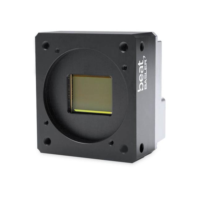
The lens is matched and validated against Omron FH-S 12 MP M42-mount cameras. Using it with third-party cameras having M42 mounts is mechanically feasible via the 46.5 mm specified flange-back, but optical performance figures including the 0.00% TV distortion and 12 MP resolution rating are qualified on Omron hardware — performance on other sensors may differ and should be verified in system acceptance testing.
Specifications: General
Brand
Omron / Sentech
Specifications: Optical
Focal length
85 mm
Lens mount
M42
Aperture (f-number)
F4.0–F16
Image circle / max sensor
φ50 mm
Optical resolution
12 MP (FH-S*12)
Telecentric
No
Working distance
285 mm (0.35×) – 864 mm (0.1×)
Specifications: Mechanical
Weight
350 g
Applications this camera is commonly selected for. Open one to see the full recommended hardware and approach.
These steps take an Omron Sentech (STC) camera from the box to a stable first image and on to your own application. They apply across the GigE Vision, USB3 Vision and CoaXPress STC families; the interface only changes how you cable and power the camera.
Download and install the Sentech SDK on the host PC. The package provides StViewer, the viewing and configuration software you use to bring the camera up, and StApi, the programming SDK you integrate later. Because the cameras are GenICam/GenTL-compliant, StApi also registers a GenTL producer, so any GenICam-compliant third-party vision software can discover and drive the camera as an alternative front end.
2. Cable, power and connect the camera
Connect according to the interface. GigE Vision: link to a Gigabit NIC (use PoE or the separate power input) and put the camera and host on the same subnet; for USB3 Vision use a USB 3.x port and a certified cable; for CoaXPress (STC) connect to a CoaXPress frame grabber, which also supplies Power-over-Coax. Then open StViewer and let it enumerate the camera. If a GigE camera does not appear, check the IP configuration and firewall, and on USB3 confirm the host bandwidth and driver.
3. Configure exposure, gain and white balance
Open the device in StViewer and start a live stream. Set exposure and gain for a well-exposed, low-noise image: raise exposure first and only add gain when more light or a faster shutter is not an option, keeping exposure short enough to freeze motion on global-shutter models. On colour cameras, run white balance under your actual production lighting. Adjust the lens aperture and focus on a representative target before tuning anything else.
4. Set the trigger and grab a first image
Start in free-run (continuous) acquisition to confirm a clean, stable image. For inline inspection switch to hardware or software triggering: select the trigger source, set the active edge and any delay, and wire the strobe or illumination to the camera's I/O so lighting fires with each exposure. Acquire and save a frame in StViewer; this saved image is your reference for the SDK stage and for downstream inspection.
5. Move to the StApi SDK (or any GenICam software)
Once the image is stable, reproduce the same settings in code. Use StApi to open the device, apply the GenICam features you validated in StViewer (exposure, gain, trigger, pixel format) and grab frames into your application via the bundled C++, C, C#/.NET or Python interfaces; the included samples are the fastest starting point. Prefer a different stack? The same GenICam/GenTL camera works with third-party vision libraries. With a reliable feed, you can route it into a deep-learning inspection such as Rosepetal for AI-based defect detection.
Frequently asked questions
At 0.1× magnification the working distance is 864 mm. The field of view width at that magnification equals the sensor width divided by 0.1. The exact value depends on your specific FH-S camera's sensor width (pixel count and pitch).
The M42 thread mount is a standard mechanical interface, so the lens will physically attach to any M42-mount camera body with a 46.5 mm flange-back distance. However, the optical performance specifications — including 0.00% TV distortion and 12 MP resolution — are qualified against Omron FH-S 12 MP platforms. Results on other cameras should be verified in your own acceptance testing.
TV distortion measures how much a straight line at the edge of the image deviates from a perfect straight line relative to image height. A value of 0.00% means no measurable rectilinear distortion is introduced by the lens across the full φ50 mm image circle. In a gauging application this means you do not need to apply a polynomial distortion correction in software — measured distances near the image edges are as accurate as those at the image centre.
The front filter thread is M52 P=0.75. This is a 52 mm diameter thread with a 0.75 mm pitch. Confirm that your intended bandpass, polarising, or neutral-density filter is available in this thread size or that a suitable step-up or step-down adapter ring is available from your filter supplier.
The lens stops down from F4.0 (widest, most light) to F16 (narrowest). For line-scan applications, where exposure time is very short and the camera moves relative to the object, maximising light throughput by operating near F4.0 is common. Stopping down toward F8–F16 increases depth of field and reduces aberrations at the field edges, which can be useful for objects with moderate height variation within the 285–864 mm working distance range.