Robot guidance turns a camera into the eyes of a manipulator. Instead of presenting parts to the robot in fixtured, repeatable positions, vision measures where each part actually is, in the robot's own coordinate frame, so the gripper can adapt to variation in real time. The engineering problem is rarely "can I see the part?" but "can I report its pose accurately and repeatably enough for the robot to act on it, cycle after cycle?"
The application splits naturally into two regimes. Flat, well-presented parts on a conveyor or tray need 2D localisation: position in X and Y plus rotation. Parts in a bin, stacked, overlapping or arriving at unknown heights and tilts, need full 3D: a point cloud from which you extract pickable poses. Both regimes live or die on the same foundation, hand-eye calibration that ties the camera's measurements to the robot's tool frame, and that is where most integration time and most field failures actually concentrate.
What robot guidance has to deliver
A vision-guided robot does not need a pretty image; it needs a trustworthy pose. The output of the vision system is a transform, the position and orientation of the part expressed in coordinates the robot controller understands, together with enough confidence to either pick or reject. Everything you specify, from the camera to the lighting to the calibration routine, exists to make that transform accurate, repeatable and fast enough for the cycle time.
Two error budgets drive the design. The first is localisation accuracy: how tightly the vision system pins down the part. This must be a fraction of the gripper's tolerance, the entry chamfer of a fixture, or the clearance to neighbouring parts in a bin. The second is the calibration error: how faithfully the camera frame maps to the robot frame. These add. A camera that resolves a feature to 0.1 mm is wasted if the hand-eye calibration drifts by half a millimetre, so both must be budgeted together rather than optimising the camera in isolation.
Cycle time is the third axis. Pick-and-place lines often demand a pose every few hundred milliseconds, which constrains acquisition time, processing time and, for 3D, the point-cloud capture method. Bin picking is usually more forgiving on rate but far more demanding on robustness, because the scene changes with every pick: parts shift, the pile collapses, and shiny or dark surfaces defeat naive imaging. Specifying for the worst-case scene, not the demo part on a clean table, is the difference between a cell that runs and one that stalls on operators every shift.
2D localisation vs 3D pose estimation
Choose the simplest geometry that the task allows. If parts always sit flat at a known, repeatable height, a single 2D camera looking straight down can deliver X, Y and rotation cheaply and fast. With a calibrated camera and a flat working plane, pixel measurements map directly to millimetres, and a single area-scan camera plus good lighting solves a large share of conveyor pick-and-place and tray-loading tasks. This is the regime to default to whenever part presentation can be controlled mechanically, because it is faster, cheaper and easier to keep stable.
Move to 3D when height, tilt or occlusion stop being negligible. Bin picking is the canonical case: parts arrive at unknown Z, leaning at arbitrary angles, partially hidden by their neighbours. Here you need a depth map or point cloud and a model-matching step that returns a full six-degree-of-freedom pose, the three positions and three rotations the robot needs to approach, grip and clear without collision. The common 3D capture methods each have a niche: structured-light and fringe-projection systems give dense, accurate clouds on static scenes; stereo, sometimes with projected texture, tolerates motion better; and time-of-flight trades fine accuracy for speed and long range. Match the method to your part size, accuracy target and how static the scene is during capture.
A frequent middle ground is 2.5D: a 2D detection that handles in-plane position and rotation, backed by a height measurement or a few 3D points to confirm pick depth and avoid crashing into a stack. It is worth resisting the urge to jump straight to full 3D when a constrained 2.5D approach, or better mechanical presentation, would meet the requirement at a fraction of the cost and cycle time.
- 2D (X, Y, rotation): flat, single-height parts with controlled presentation; one area-scan camera plus lighting.
- 2.5D: 2D detection with a height/depth check to set pick depth and avoid collisions.
- 3D (full 6-DoF pose): bin picking, stacked or tilted parts, unknown Z; requires a point cloud and model matching.
- Structured-light/fringe for accuracy on static scenes; stereo for motion tolerance; time-of-flight for speed and range.
Hand-eye calibration: where accuracy is won or lost
Calibration is the heart of robot guidance, and it is where most projects underestimate the effort. The vision system measures pose in its own frame; the robot acts in another. Hand-eye calibration computes the rigid transform between them so a detected part can be commanded as a pick. The geometry depends on the mounting: an eye-in-hand camera moves with the robot wrist and is calibrated against the tool frame, while an eye-to-hand camera is fixed above the workspace and calibrated to the robot base. Eye-in-hand gives flexible viewpoints and the ability to re-image after a coarse move; eye-to-hand gives a stable, repeatable view and keeps the camera away from impacts and cable flex.
Good calibration needs a stable, known reference, typically a precise calibration target imaged across a well-distributed set of robot poses spanning the working volume, not clustered in one corner. Lens distortion must be characterised and removed first, because residual distortion at the image edges injects pose error exactly where large parts are measured. The result should be validated by commanding picks across the whole workspace and measuring real placement error, not by trusting the calibration's internal residual alone.
Calibration is not set-and-forget. Thermal drift, a knocked camera bracket, a re-mastered robot or a swapped lens all break the transform, and the symptom on the floor is a slow creep in pick offset rather than an obvious fault. Designing in a rigid, repeatable camera mount, a periodic verification routine and an easy re-calibration procedure is part of specifying the system, not an afterthought. This is precisely the kind of full-system detail that benefits from integration experience rather than a parts list.
Recommended hardware and why
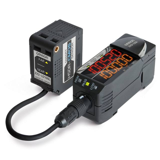
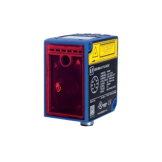
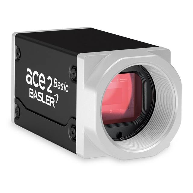
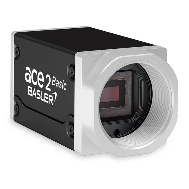
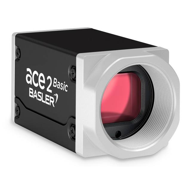
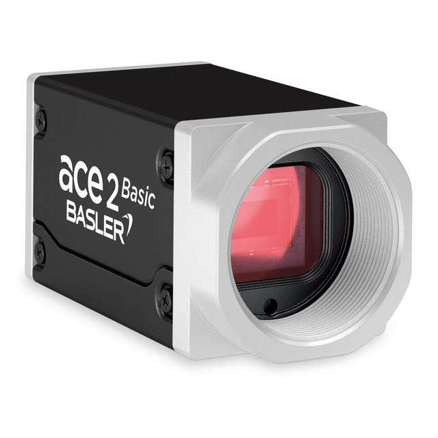
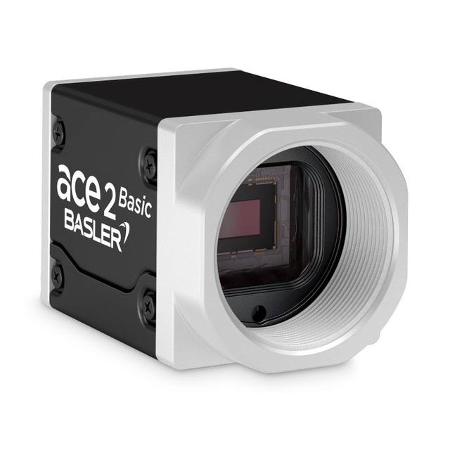
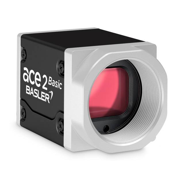
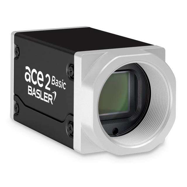
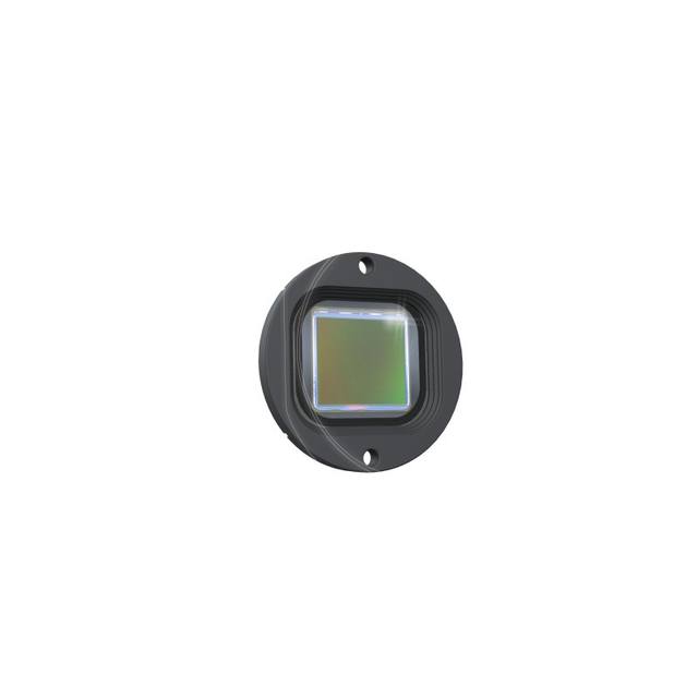
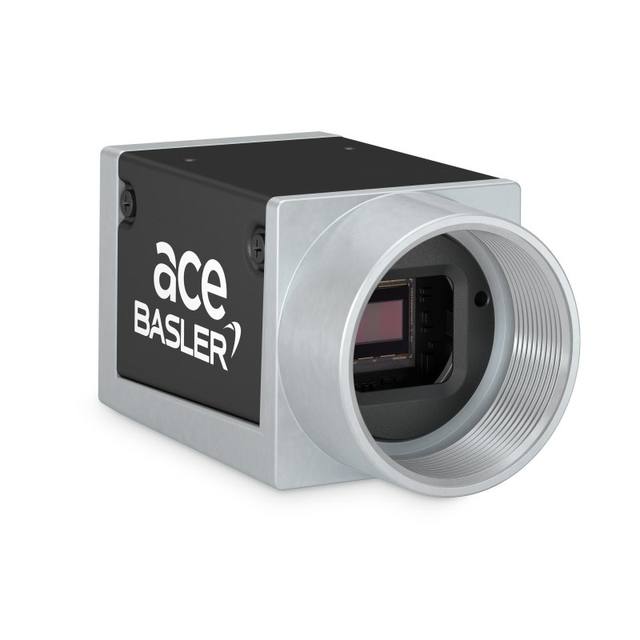
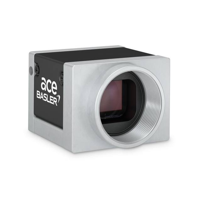
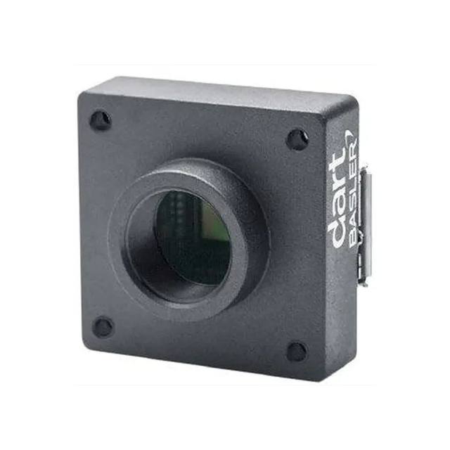
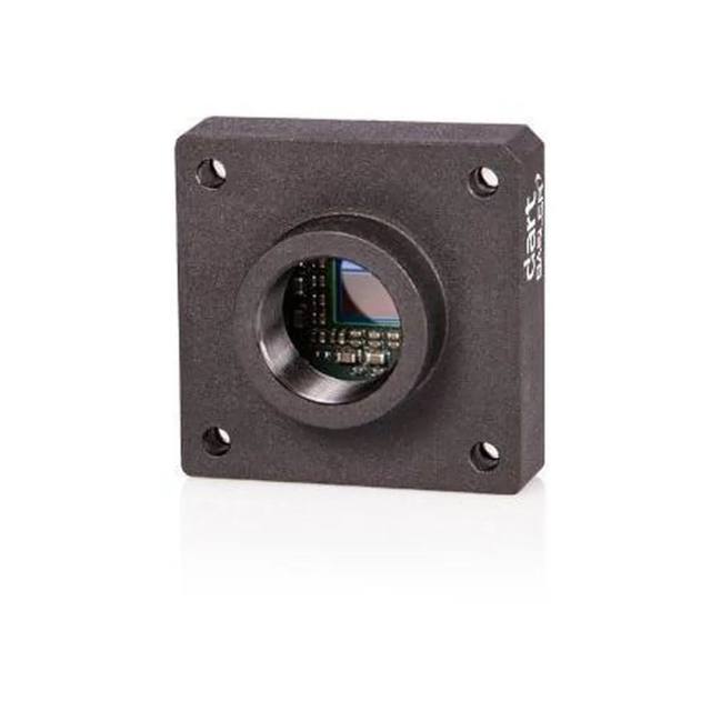
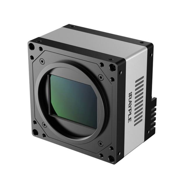
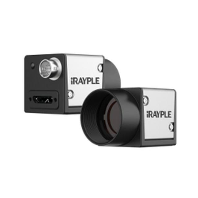
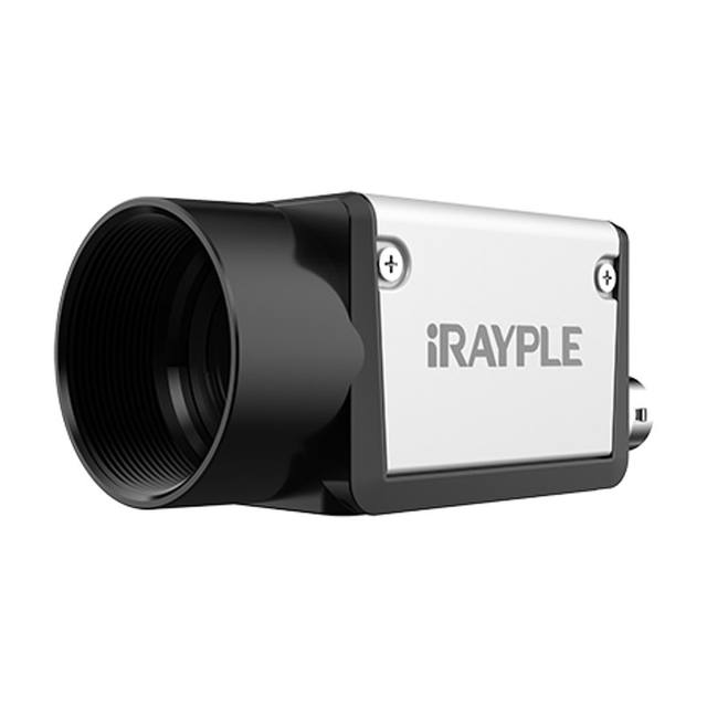
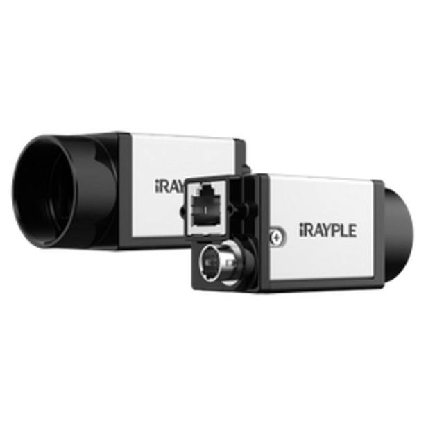
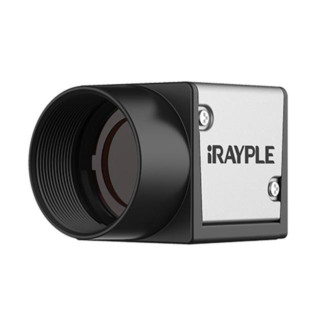
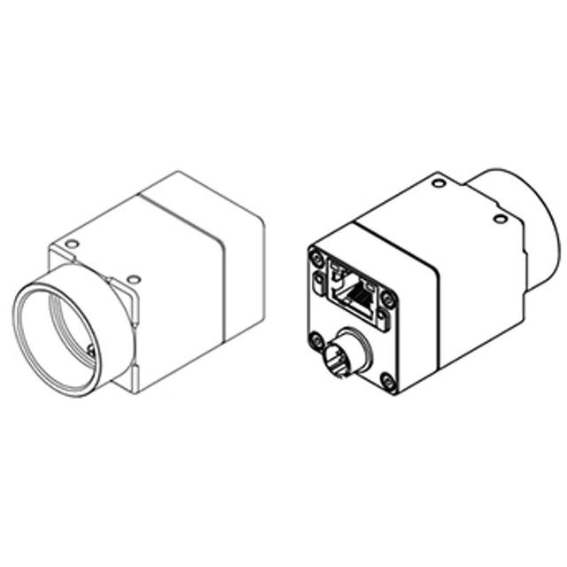
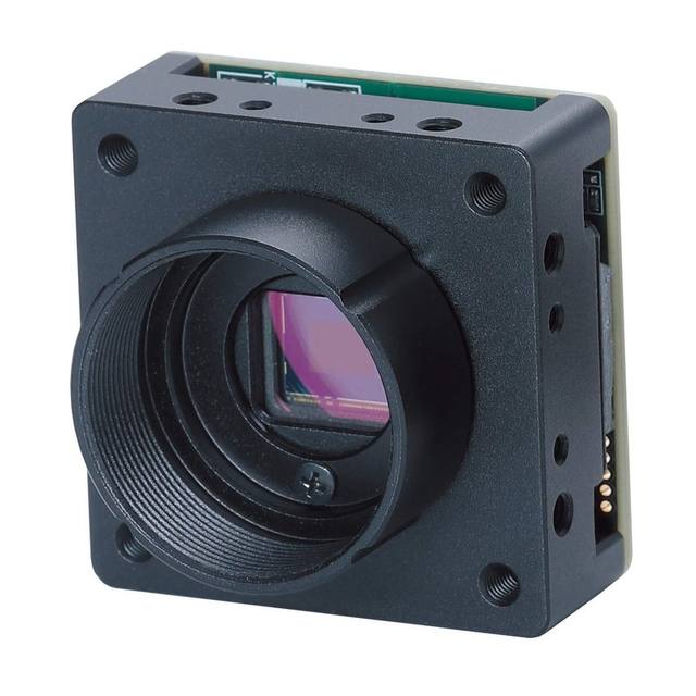
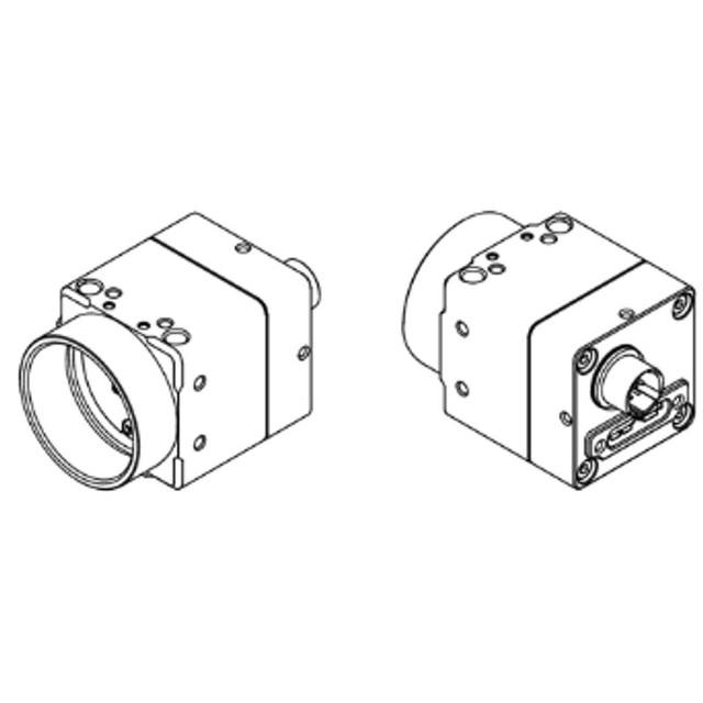
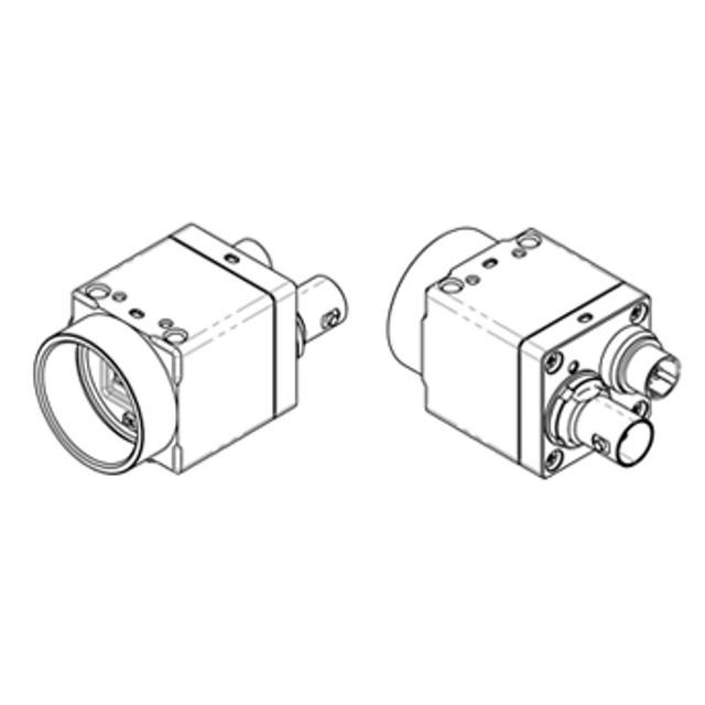
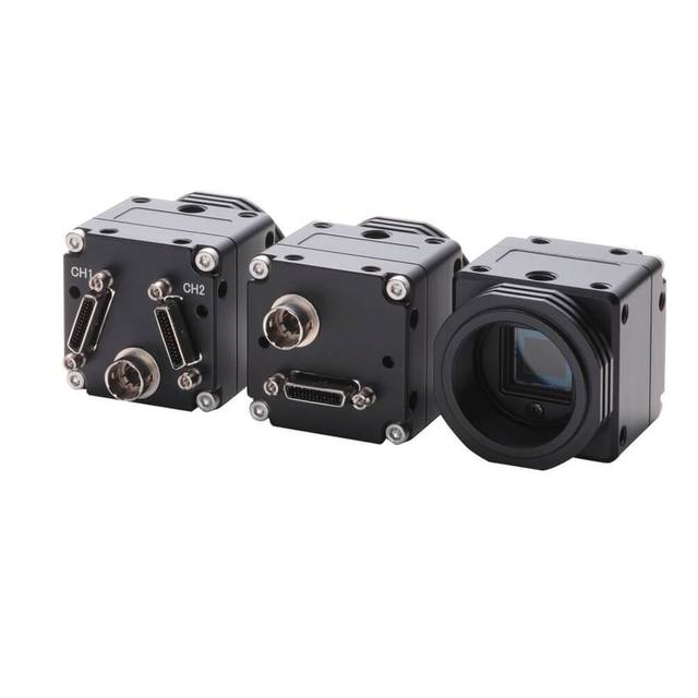
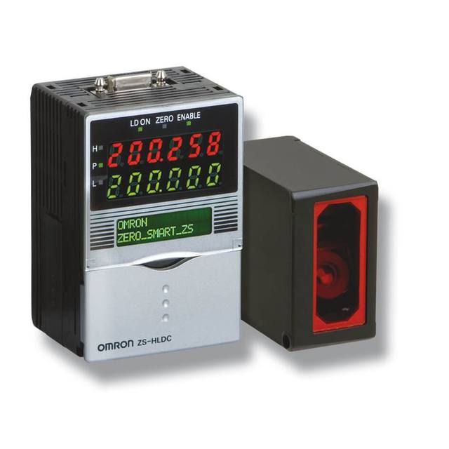
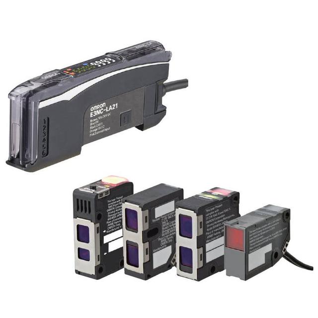
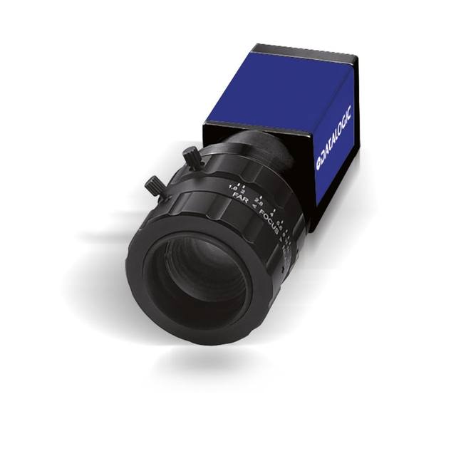
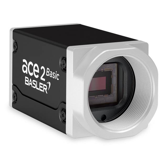
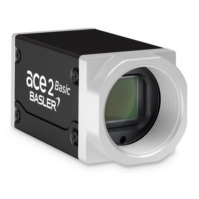
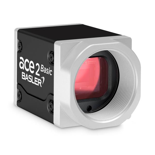
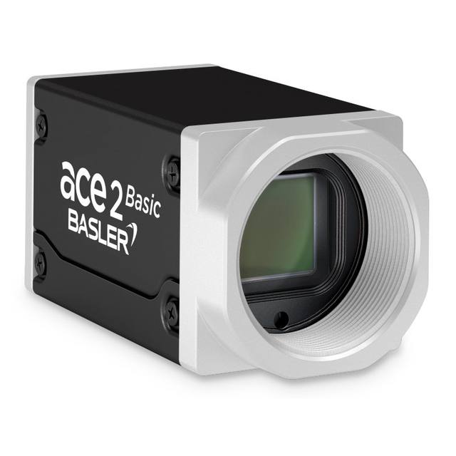
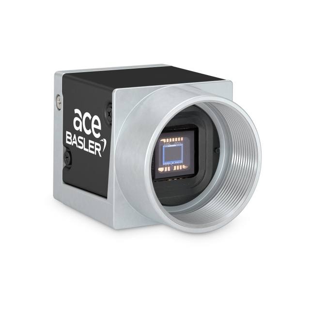
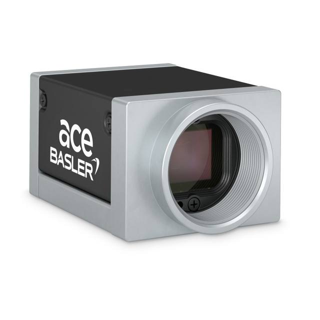
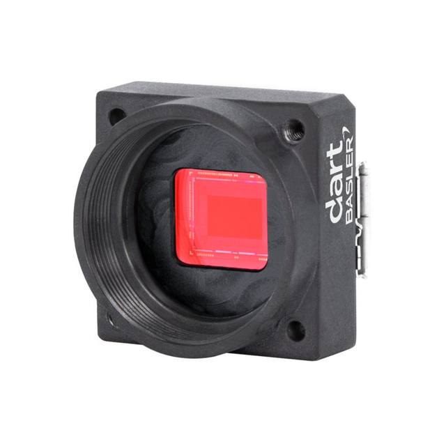
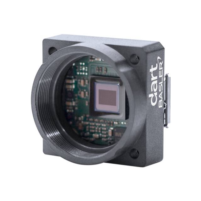
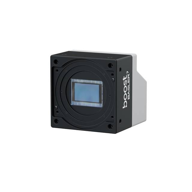
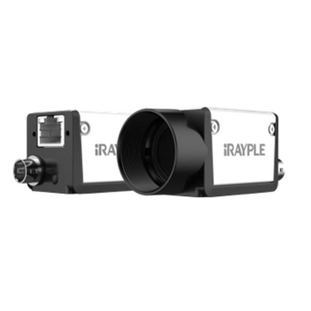
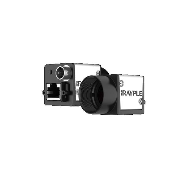
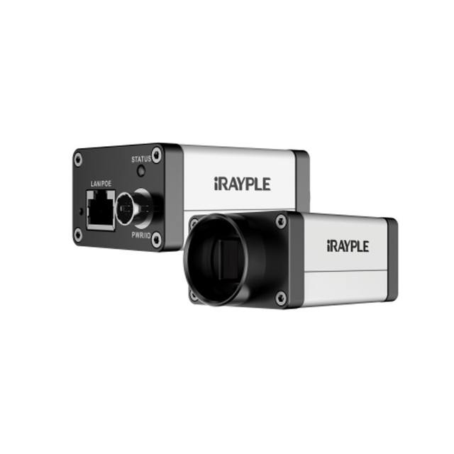
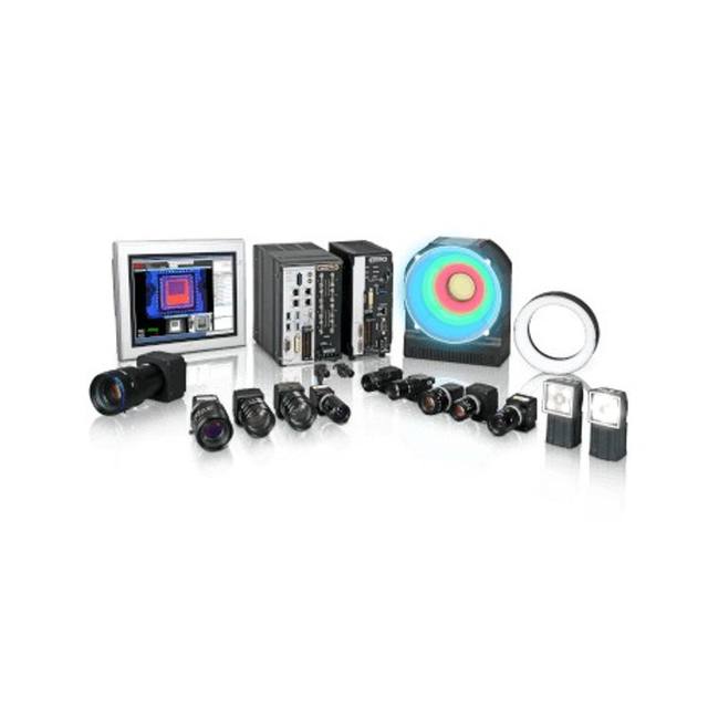
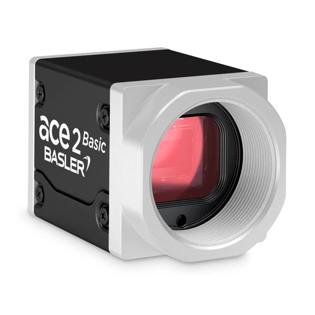
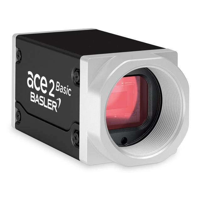
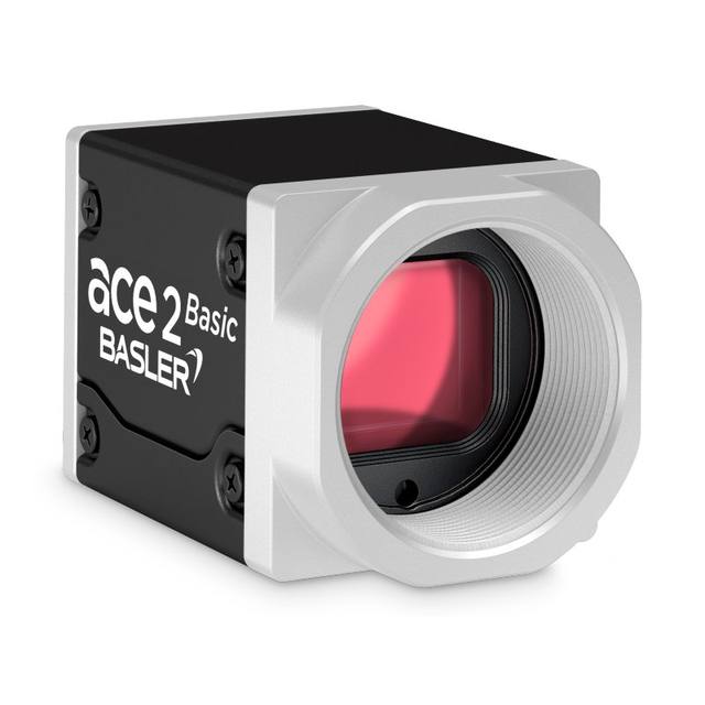
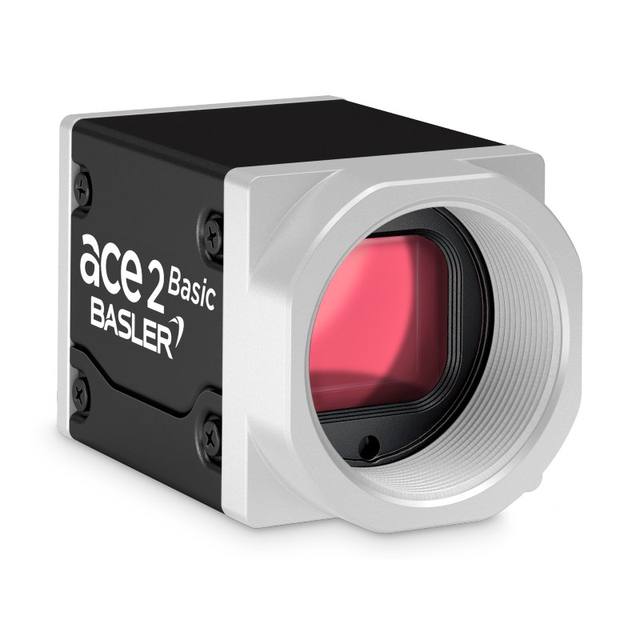
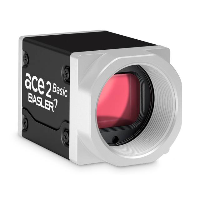
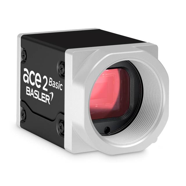
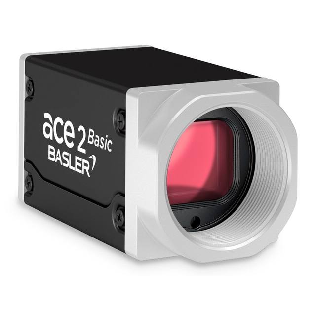
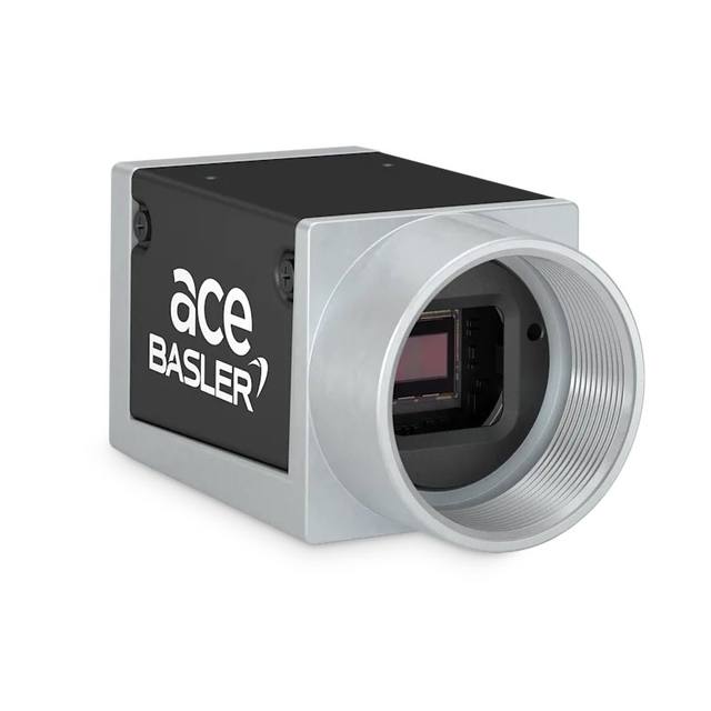
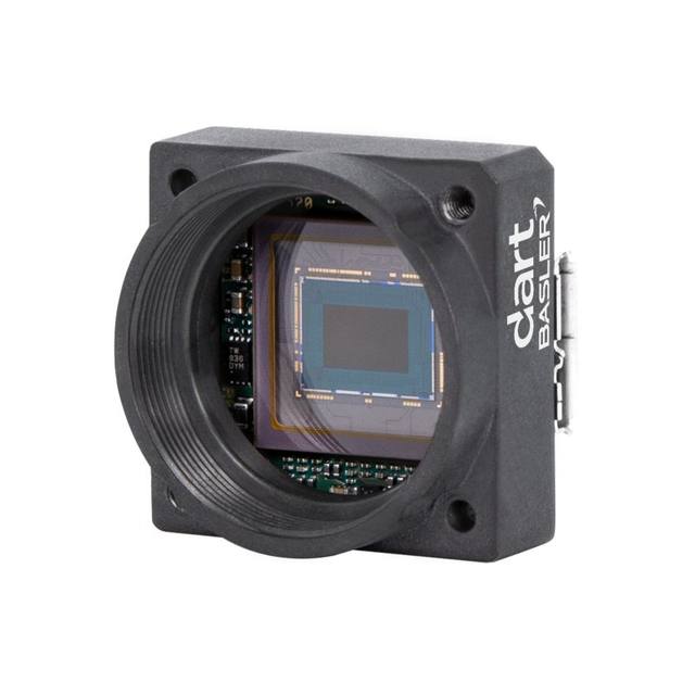
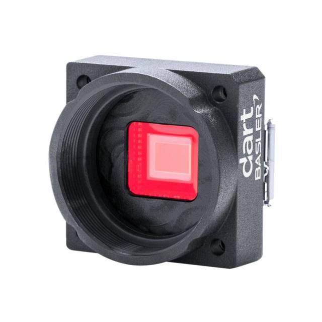
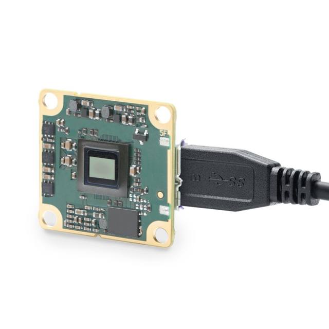
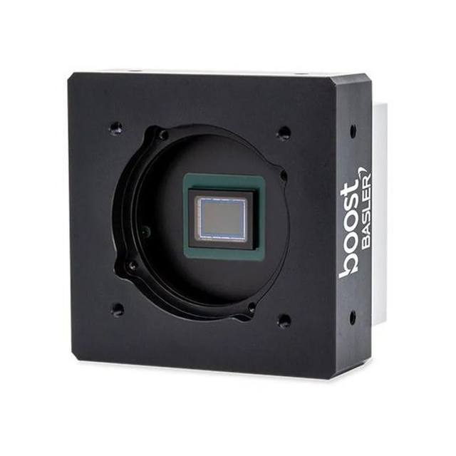
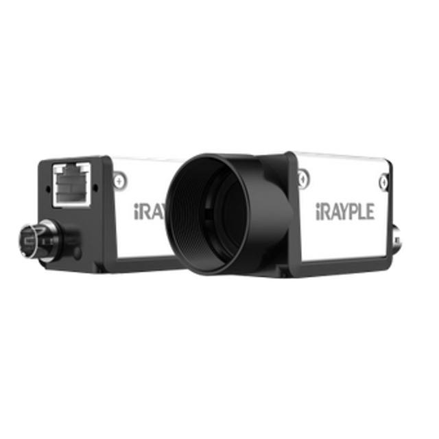
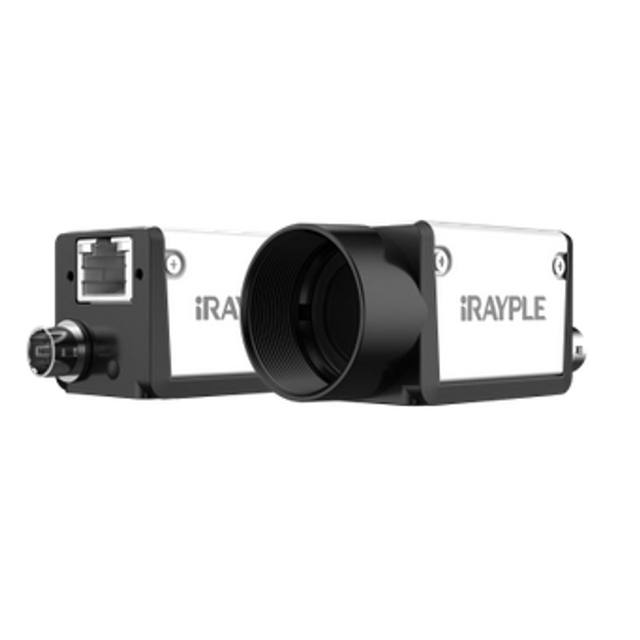
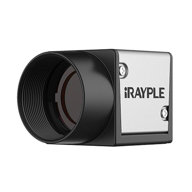
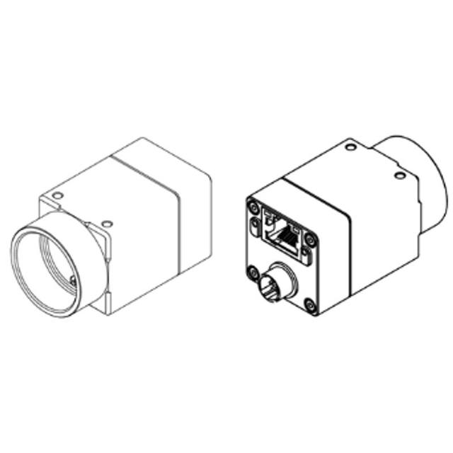
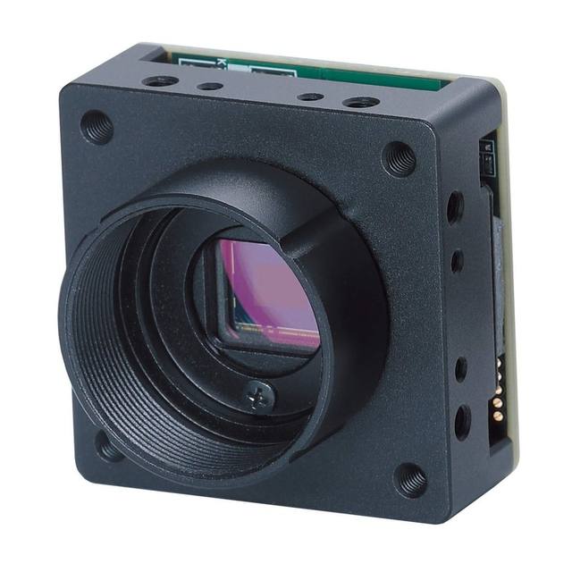
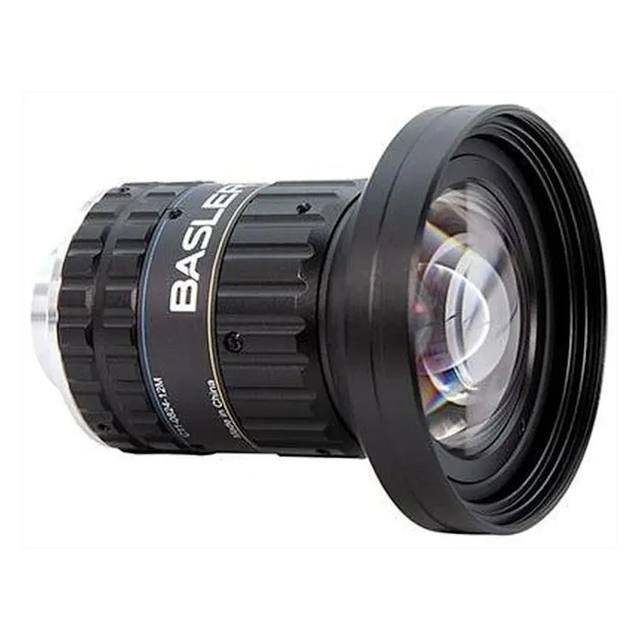
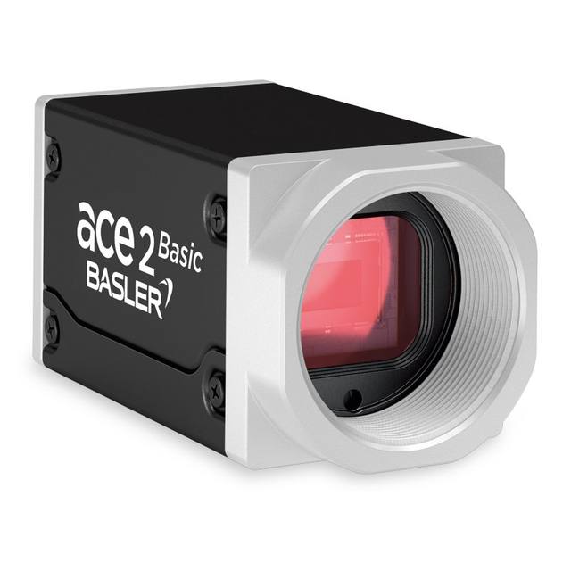
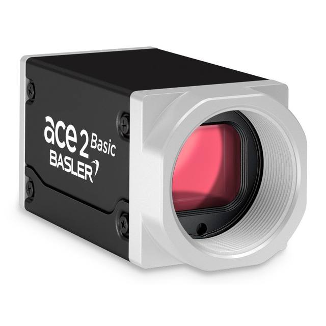
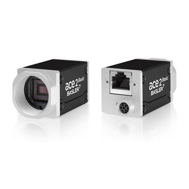
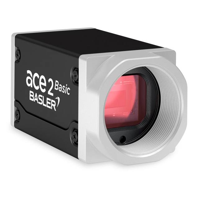
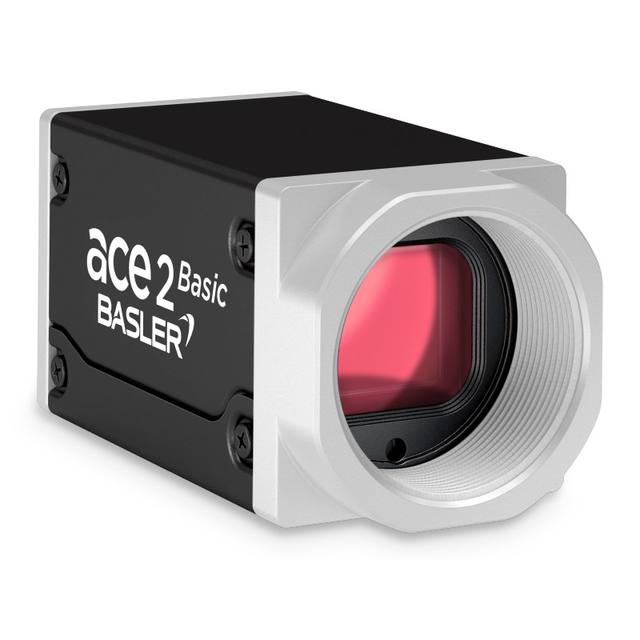
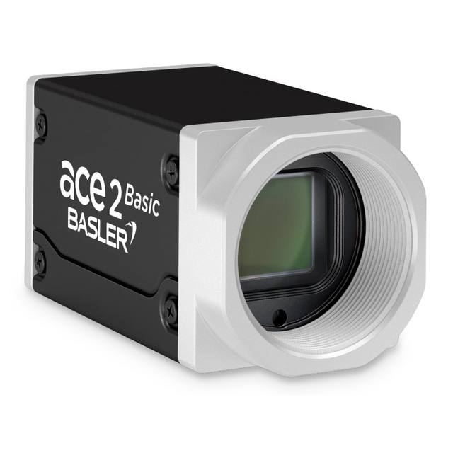
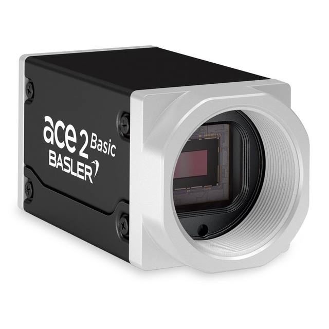
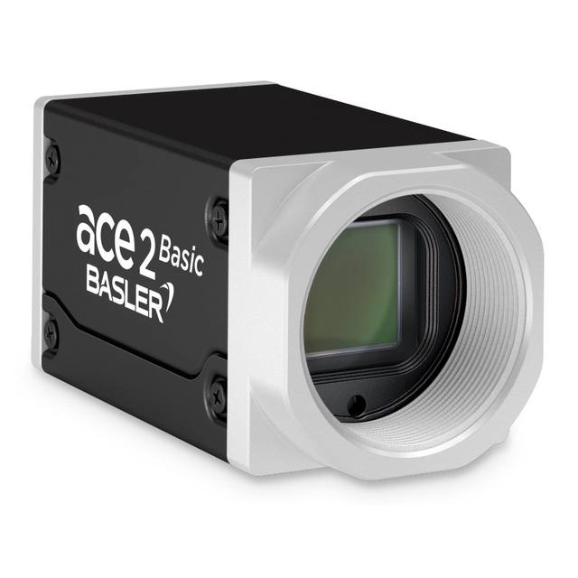
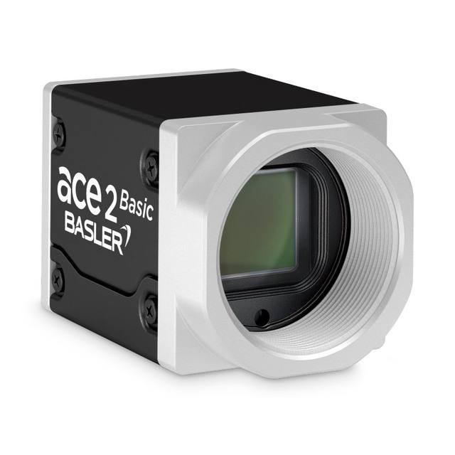
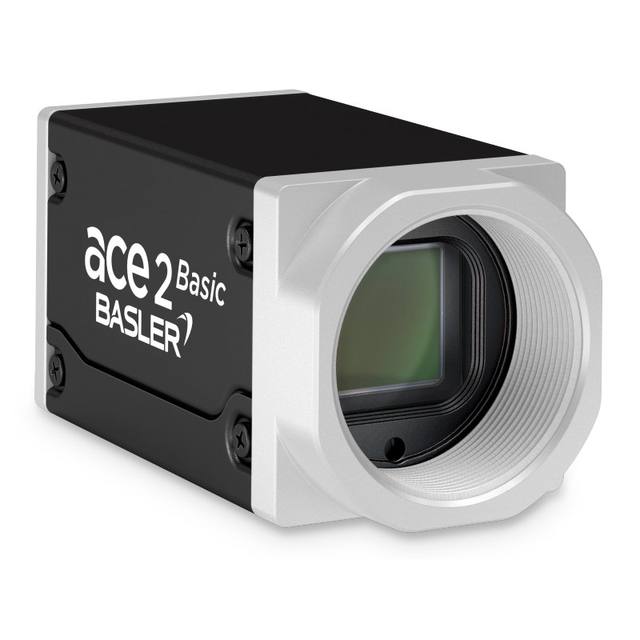
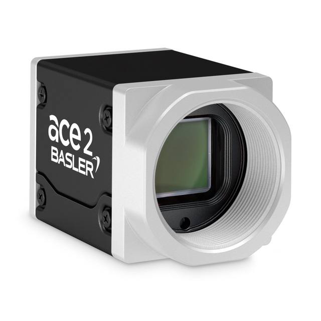
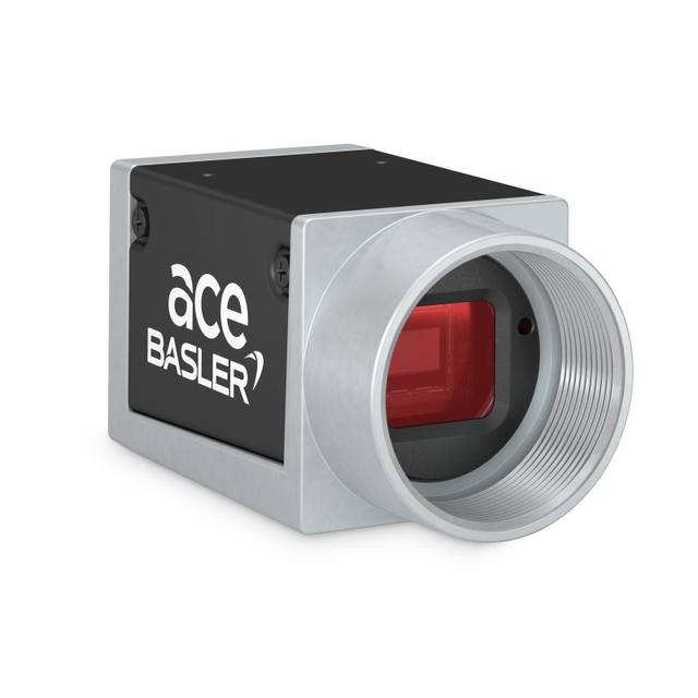
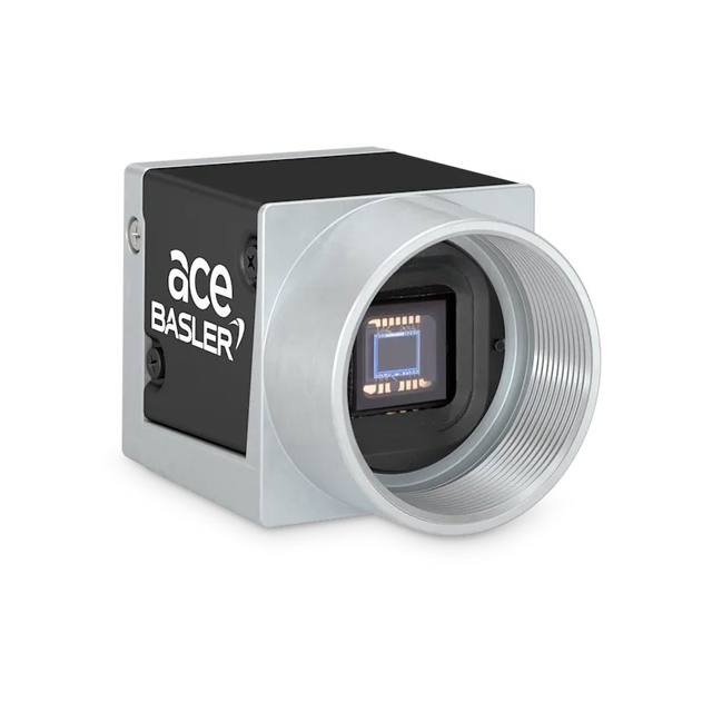
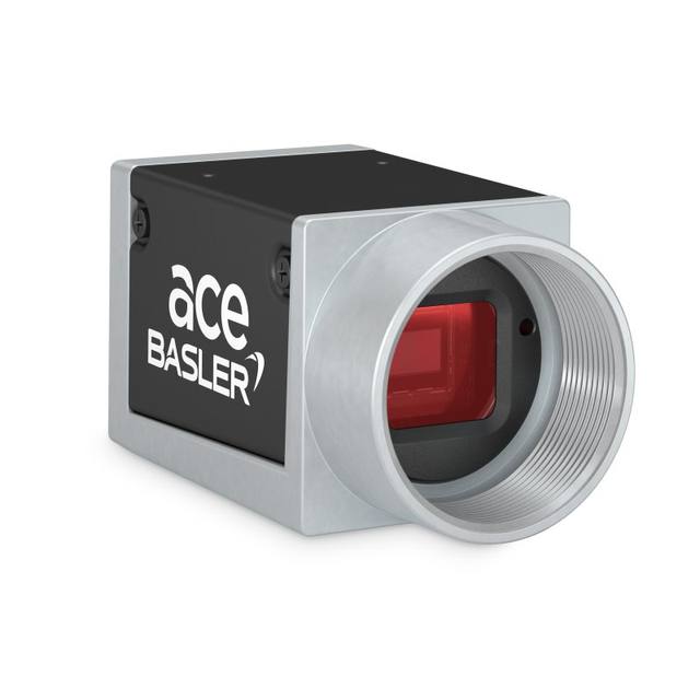
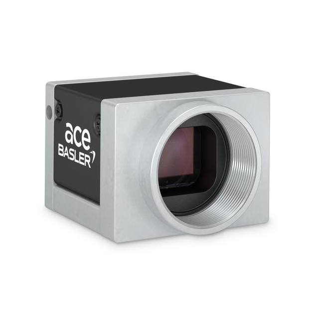
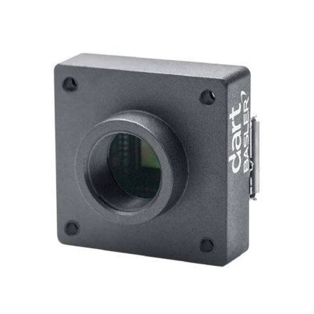
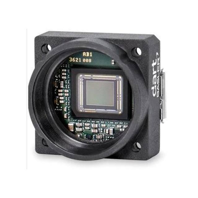
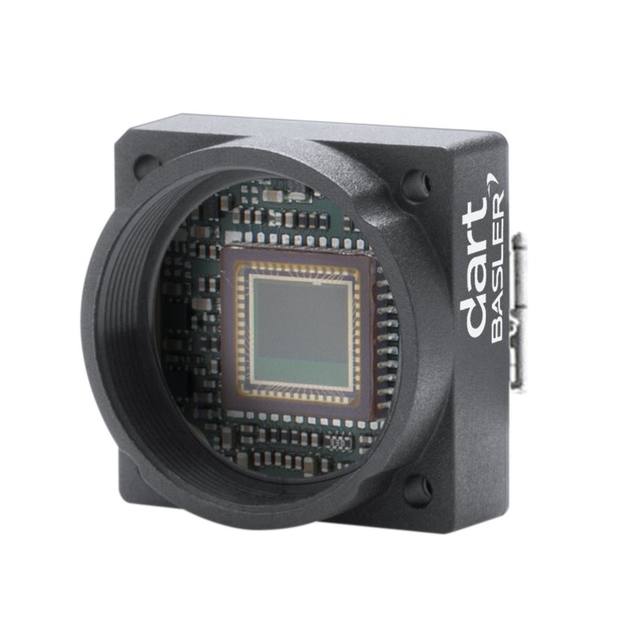
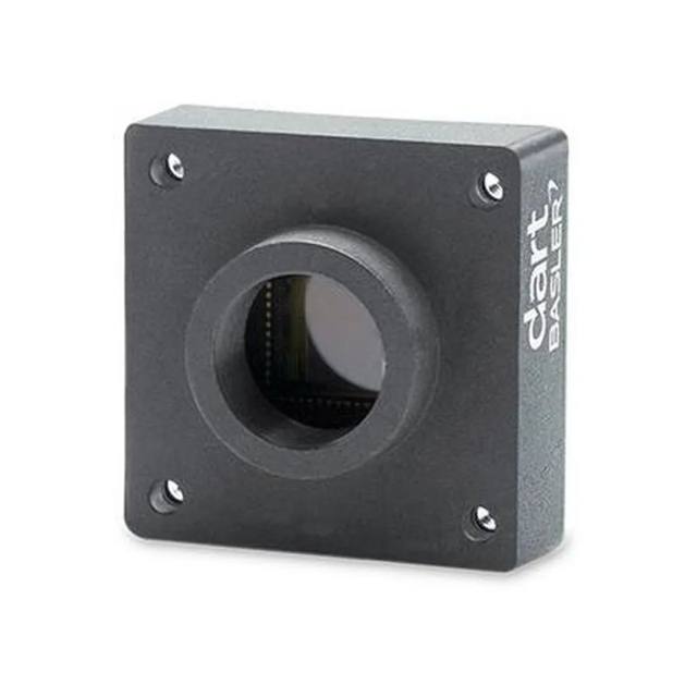
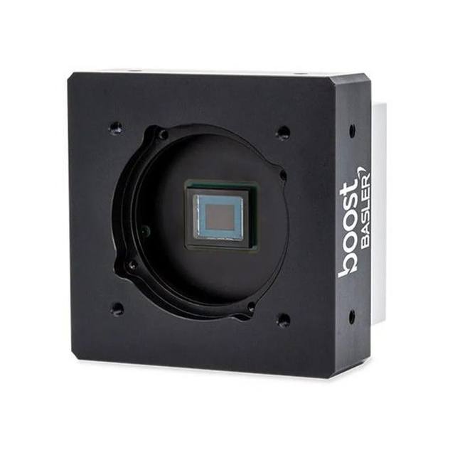
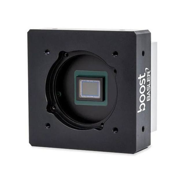
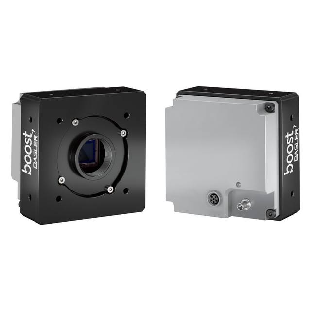
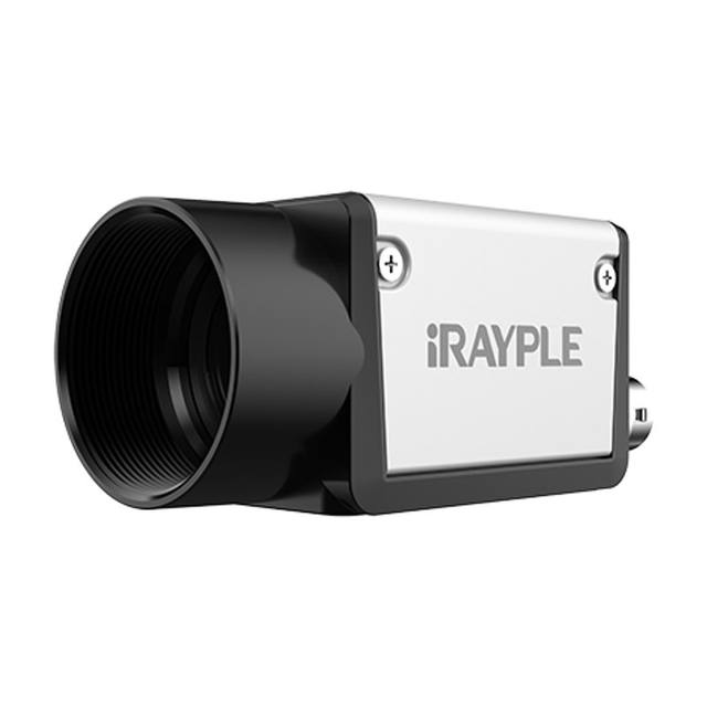
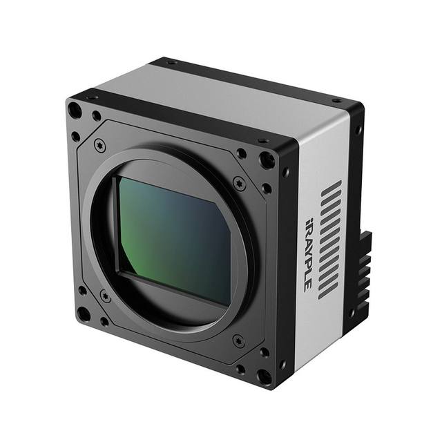
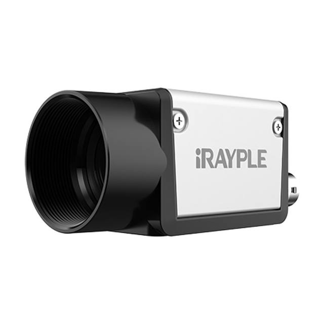
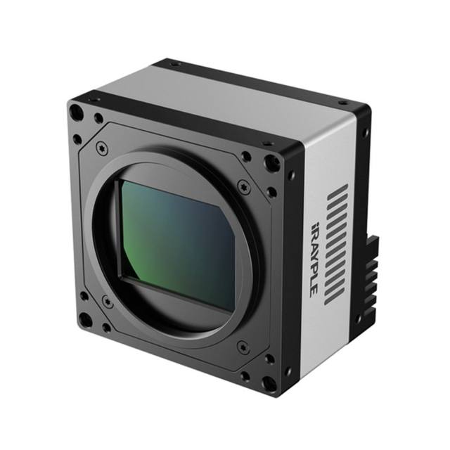
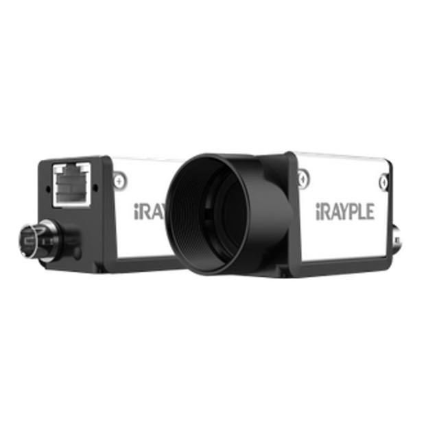
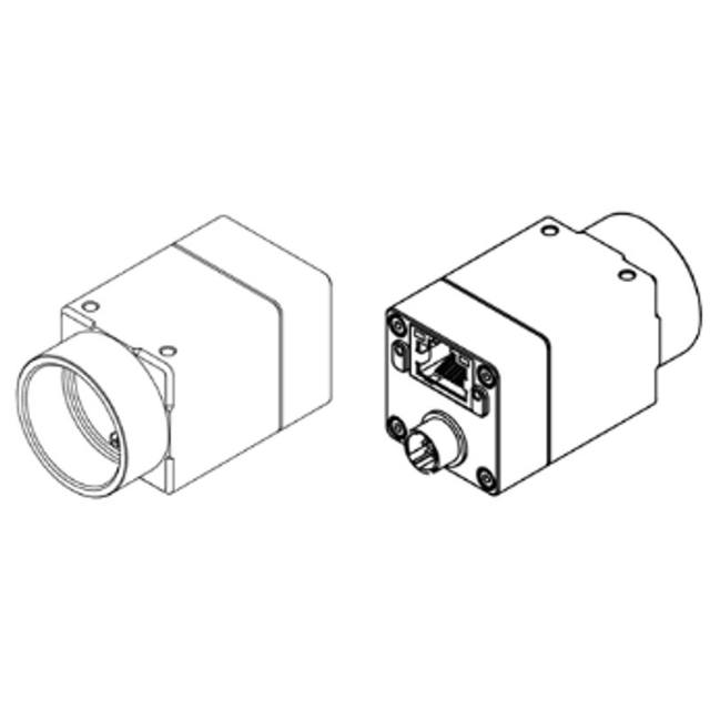
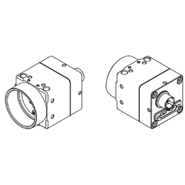
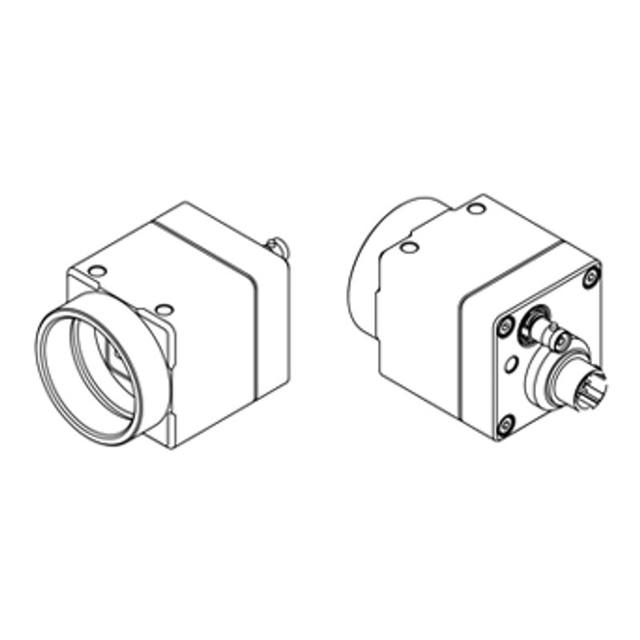
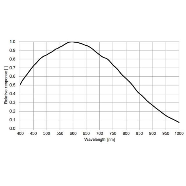
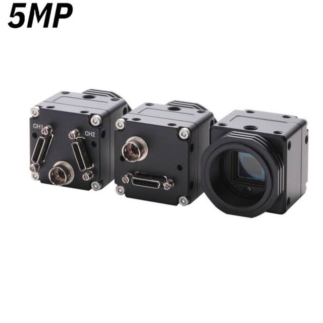
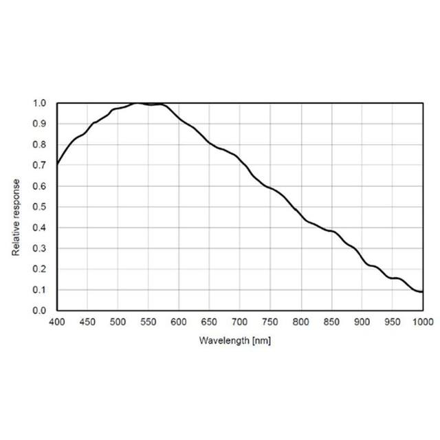
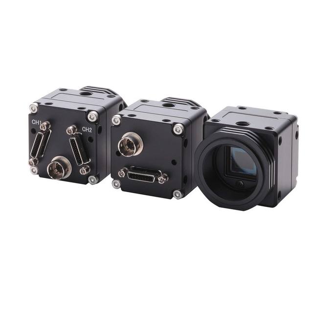
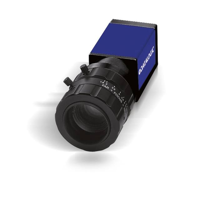
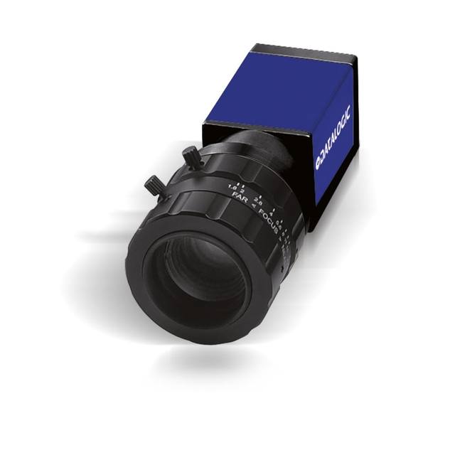
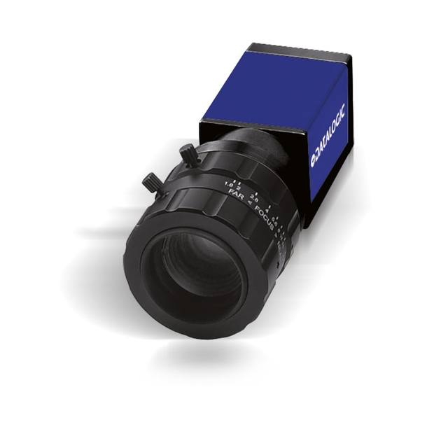
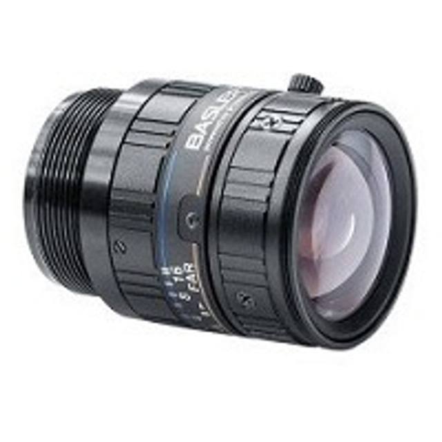
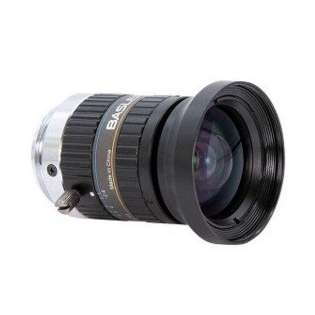
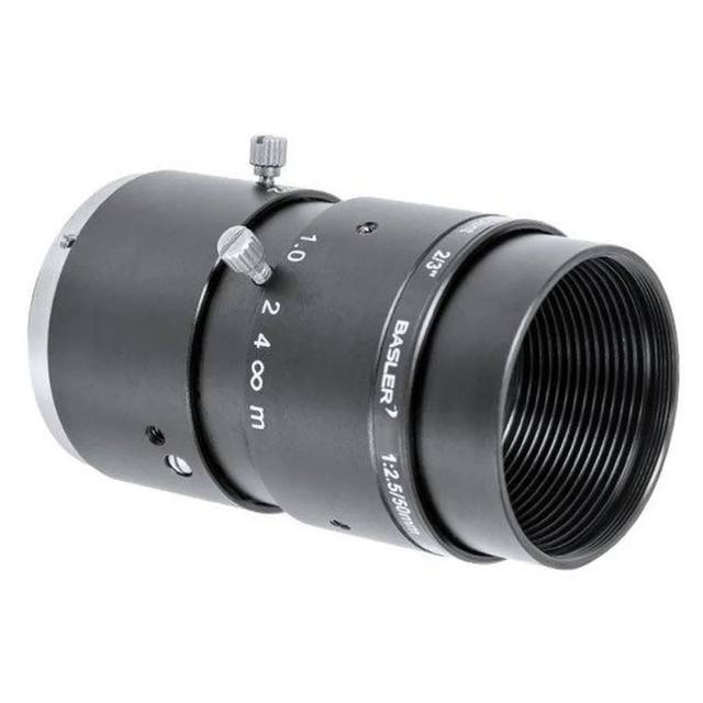
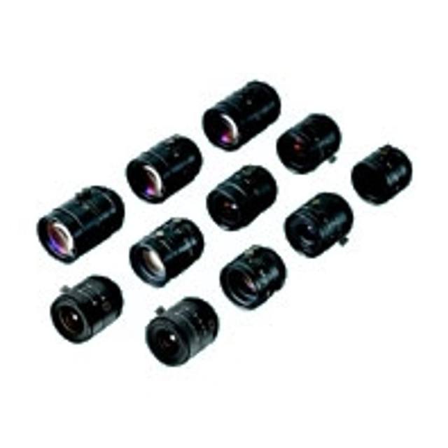
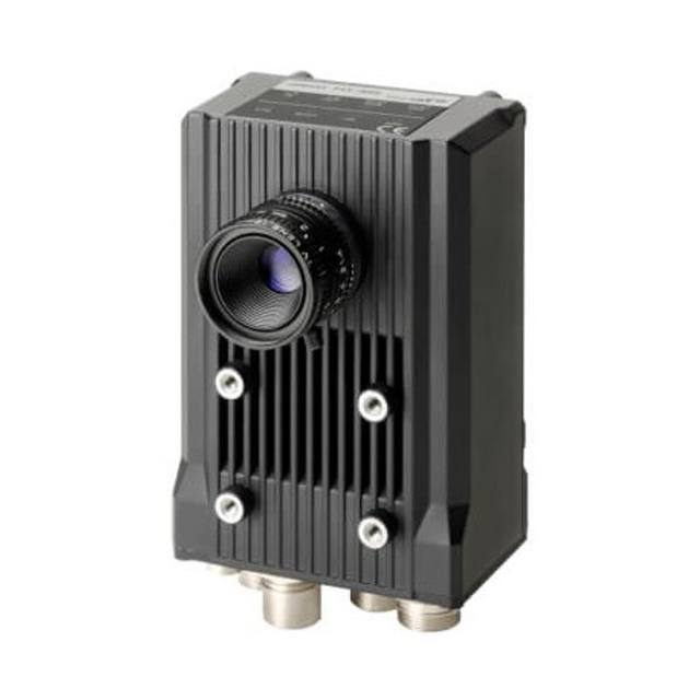
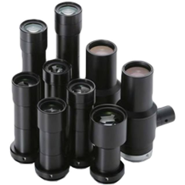
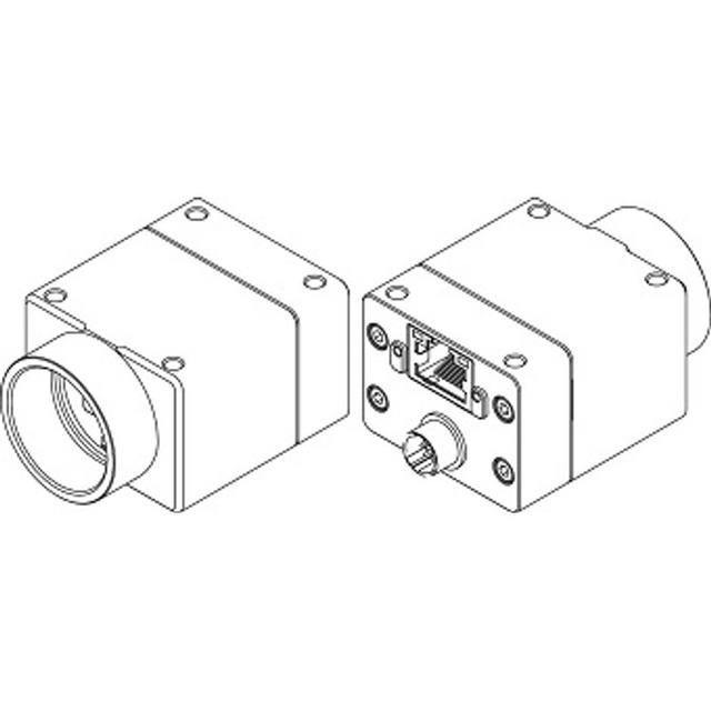
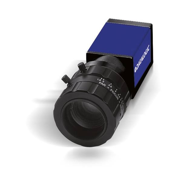
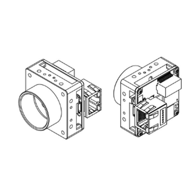
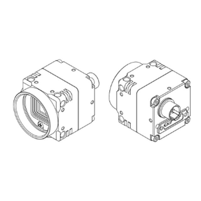
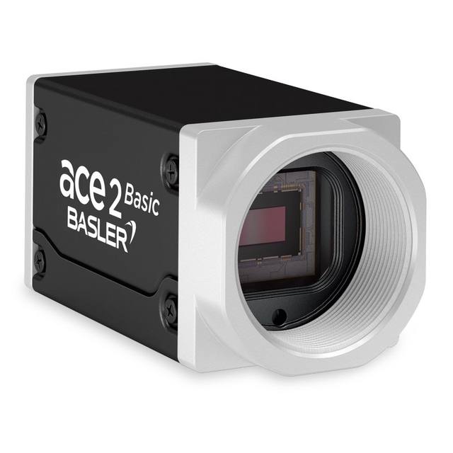
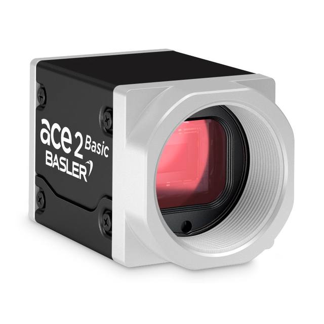
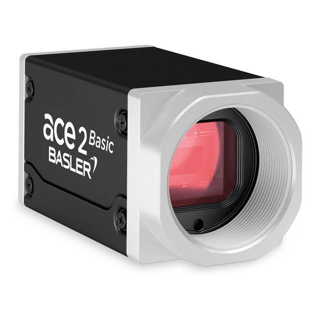
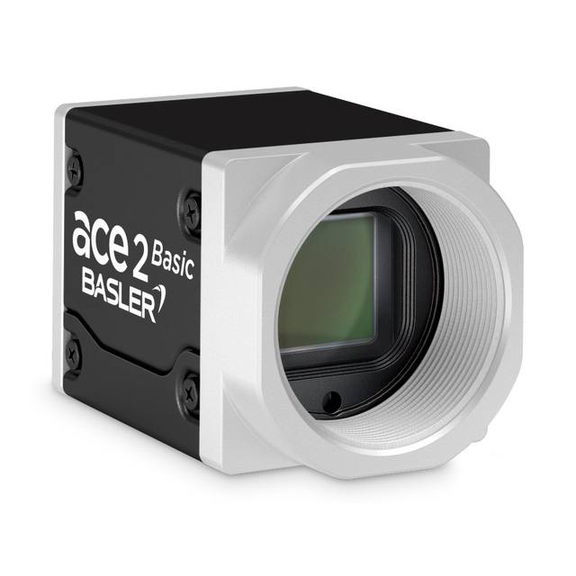
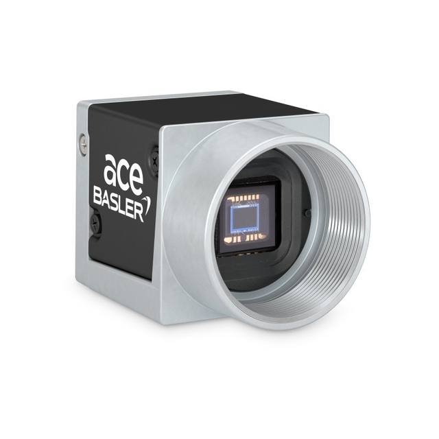
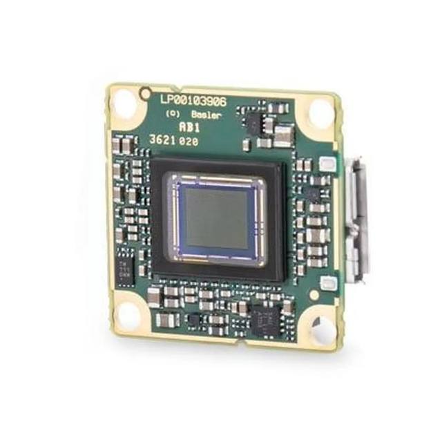
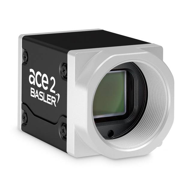
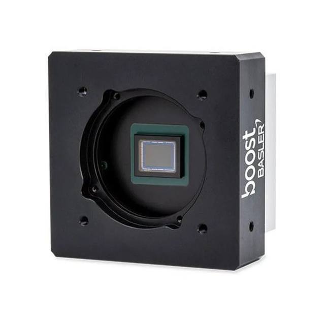
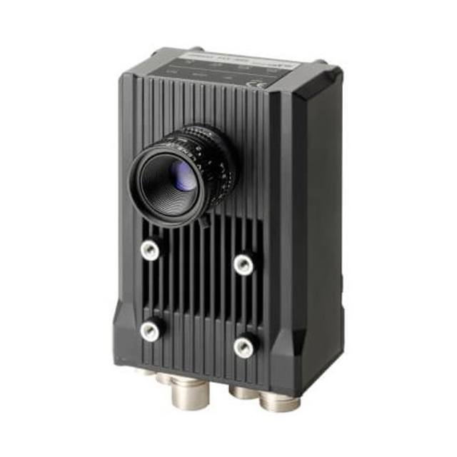
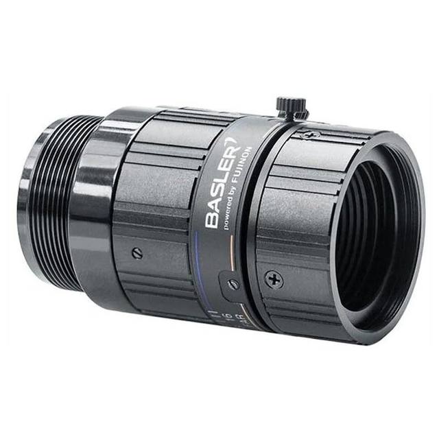
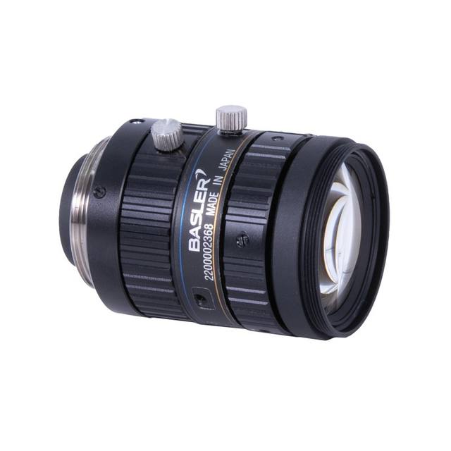
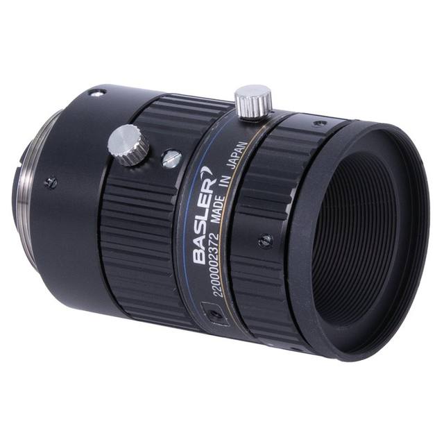
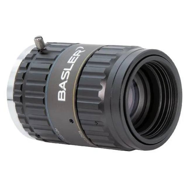
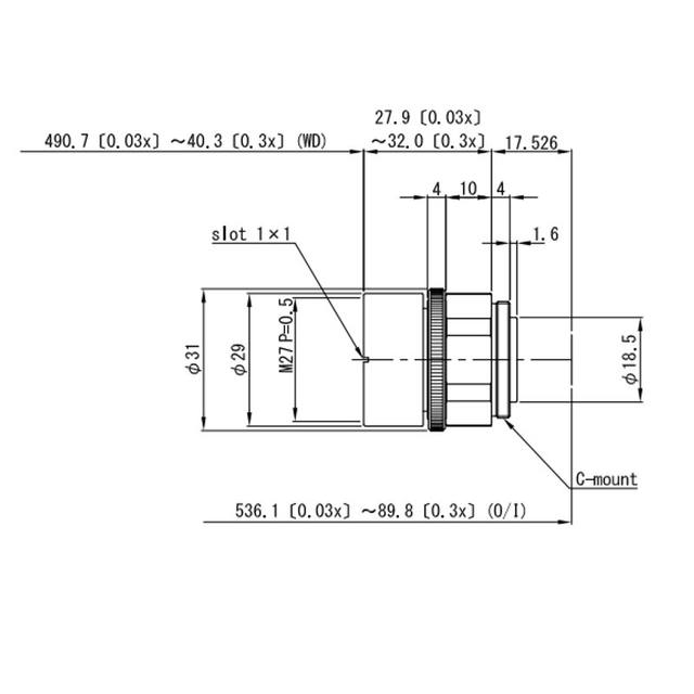
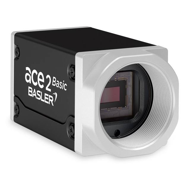
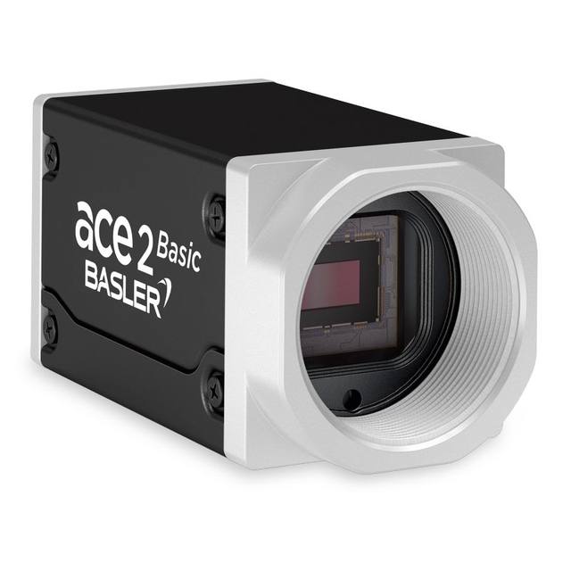
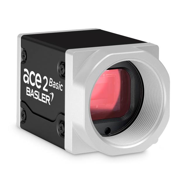
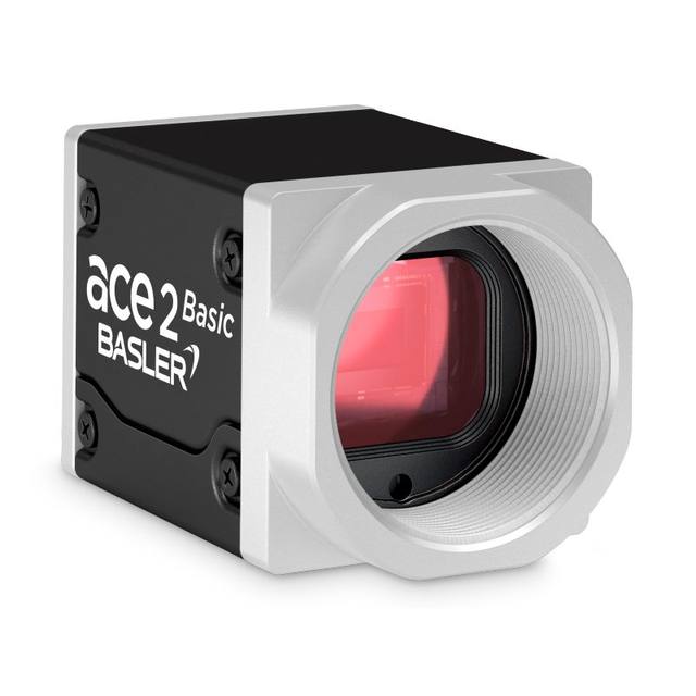
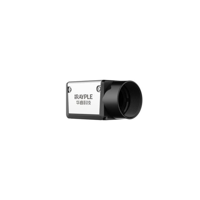
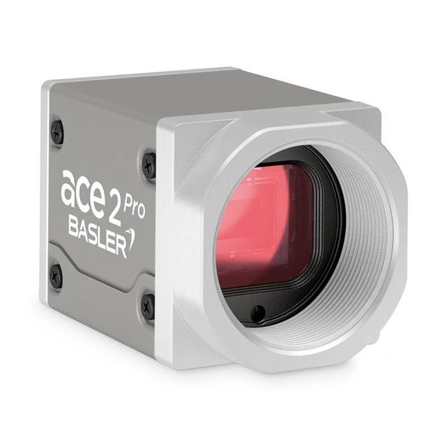
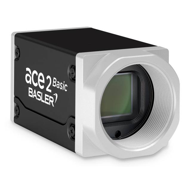
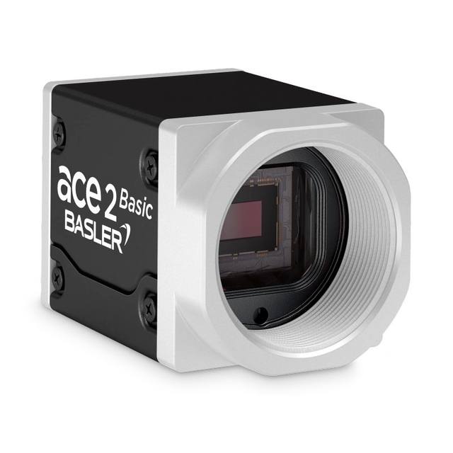
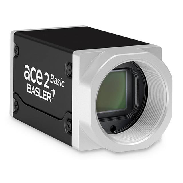
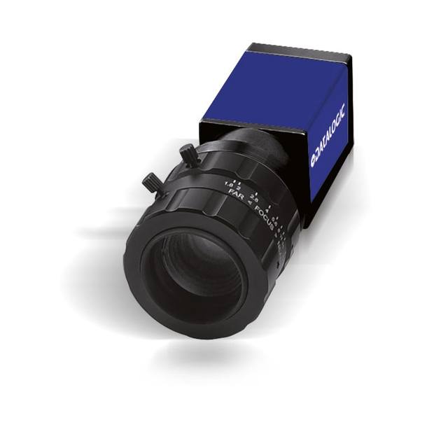
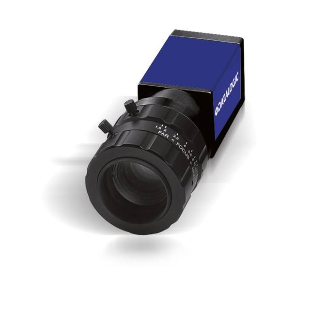
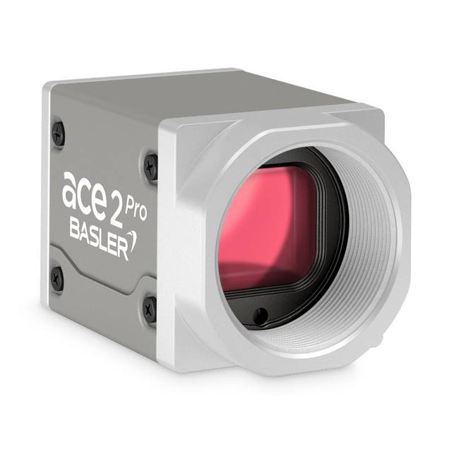
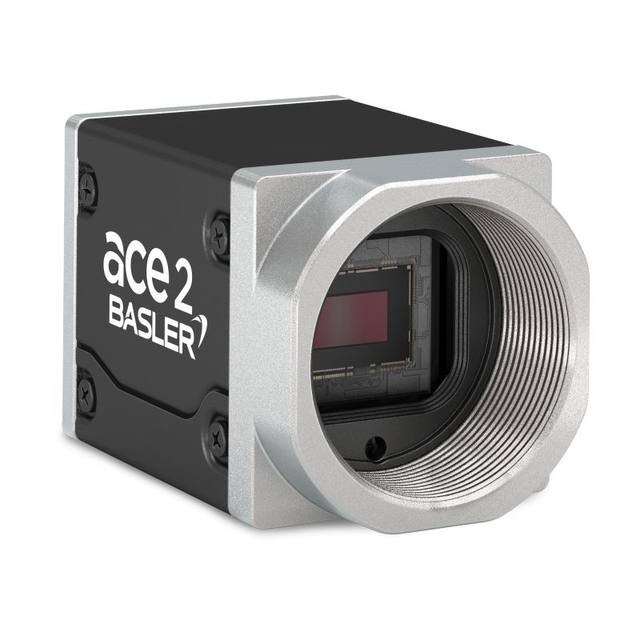
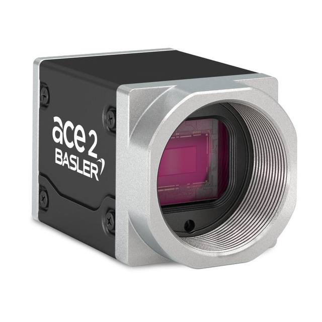
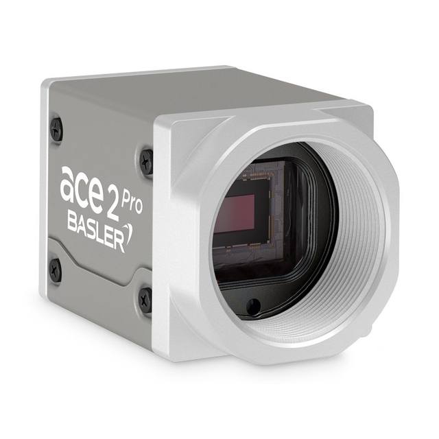
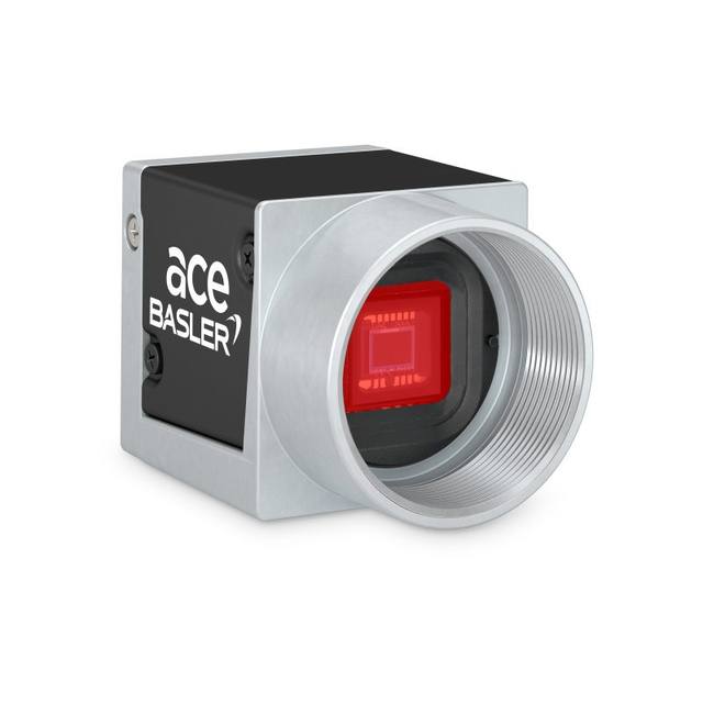
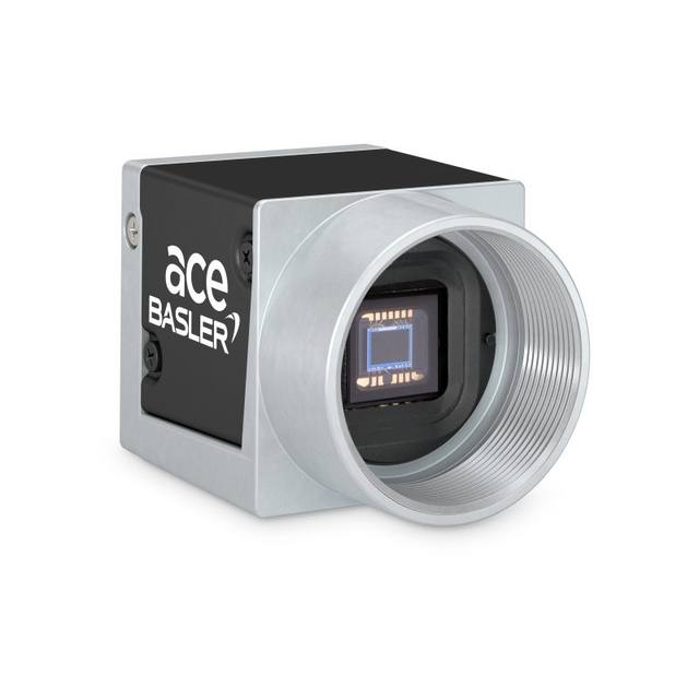
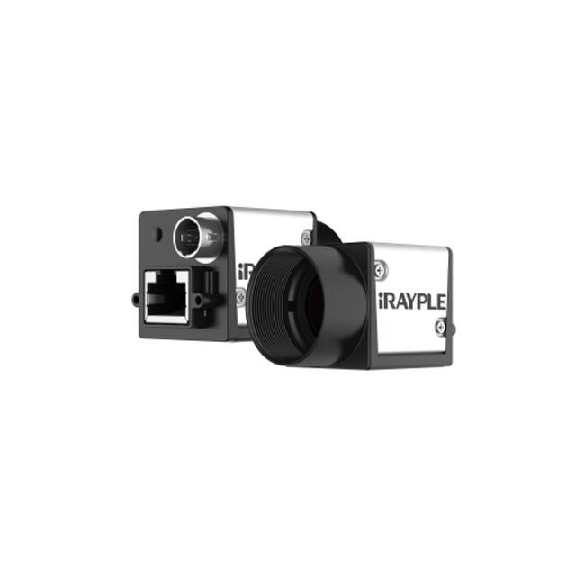
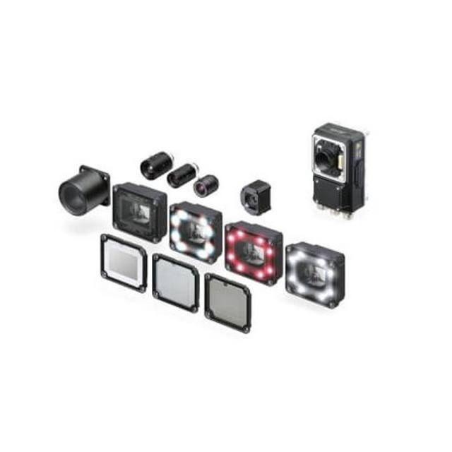
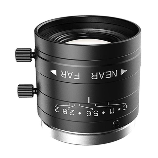
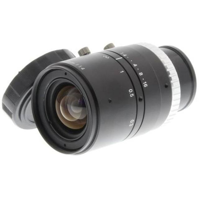
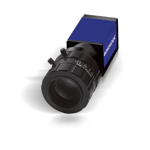
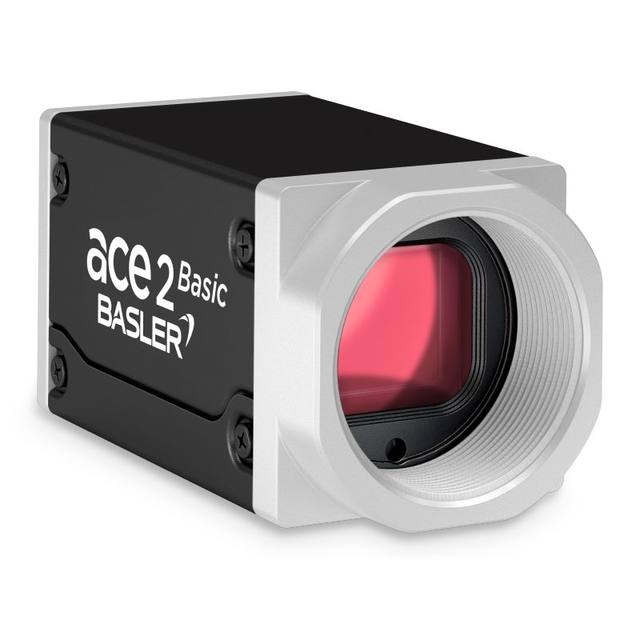
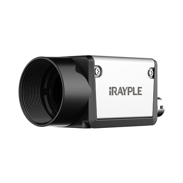
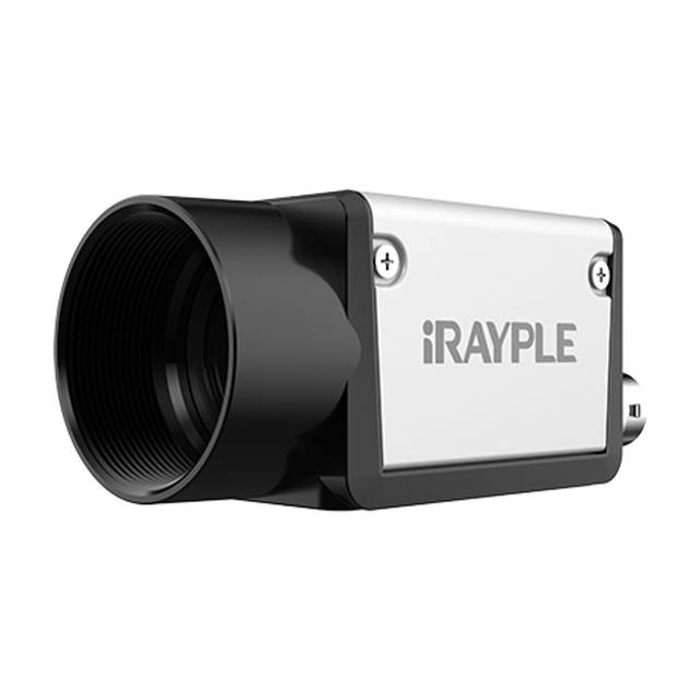
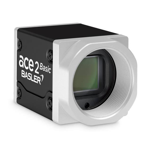
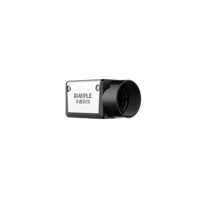
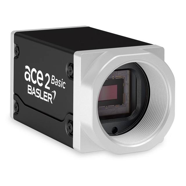
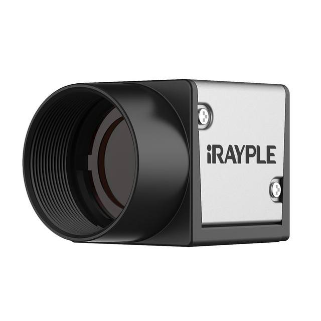
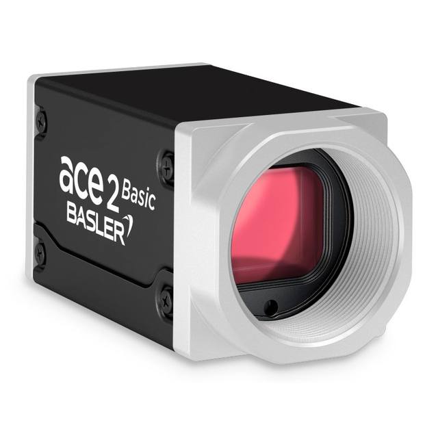
For anything beyond flat, single-height presentation, a 3D camera is the core sensor. Specify it around the working volume and the accuracy budget: the depth field of view must cover the bin or fixture, and the depth noise and lateral resolution must comfortably beat your pose tolerance, with margin for the calibration error that adds on top. Capture method matters as much as headline accuracy, structured-light for dense, accurate clouds on a settled scene; stereo or projected-texture stereo where the scene or robot moves during capture; time-of-flight where range and speed outrank fine accuracy. Catalog 3D options, alongside area-scan cameras from Basler, iRAYPLE and Omron/Sentech (STC) for 2D guidance, let you match sensor to regime rather than forcing one device onto every task.
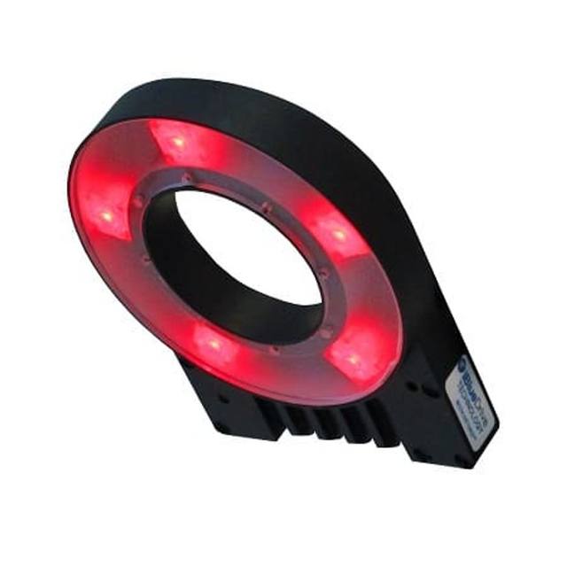
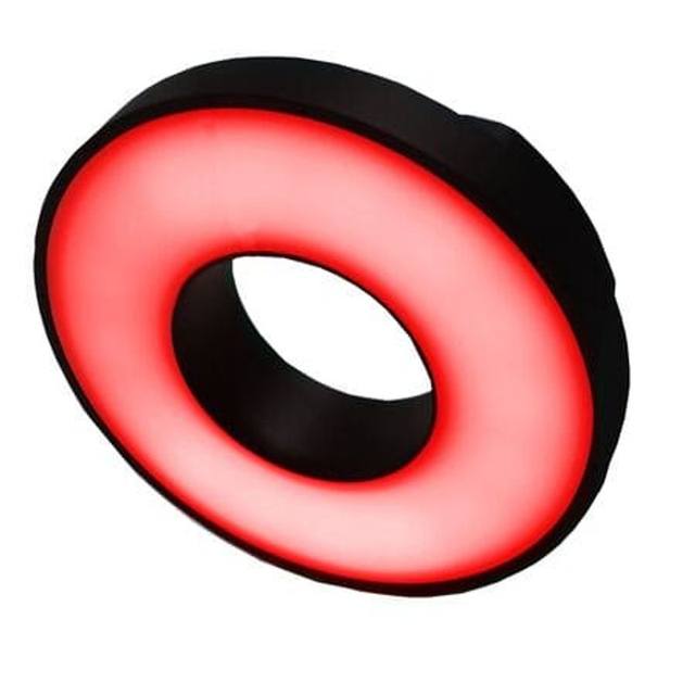
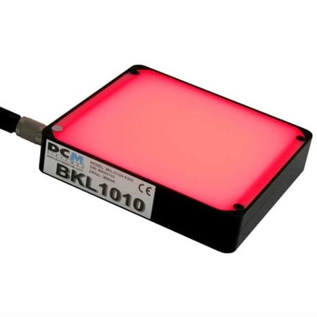
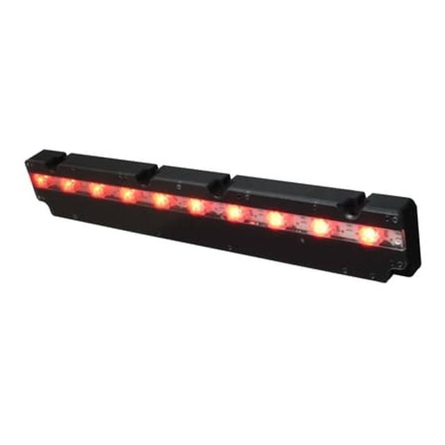
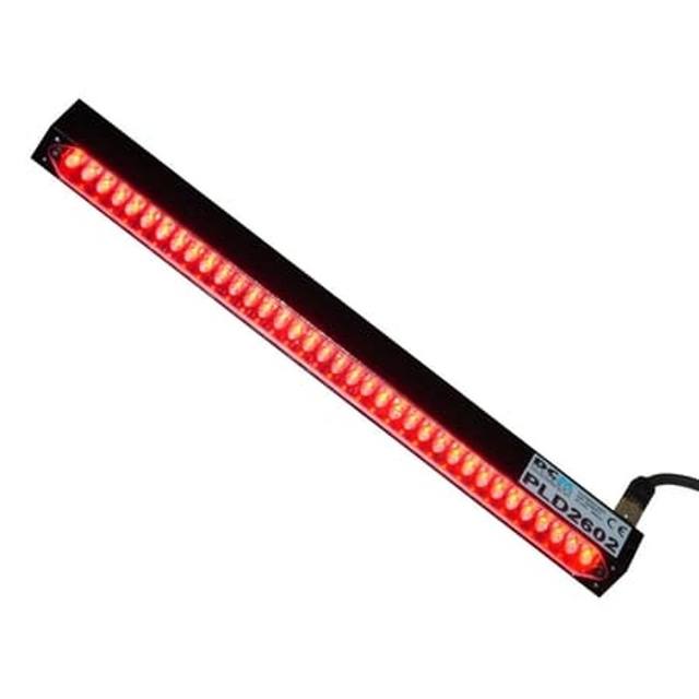
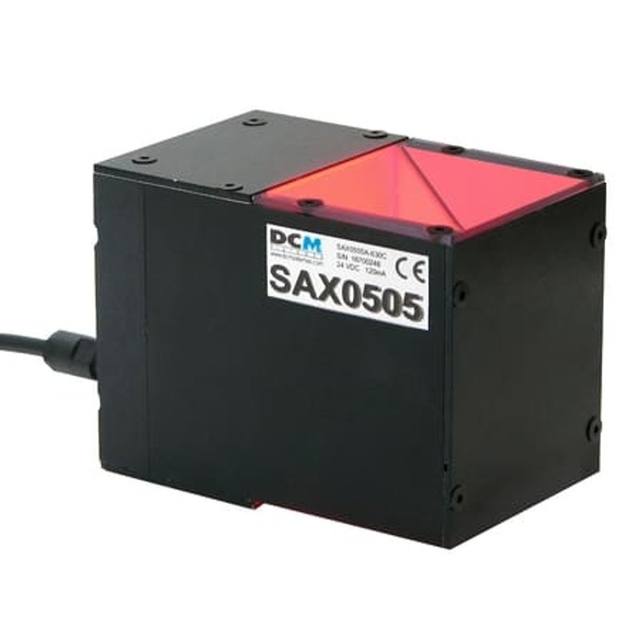
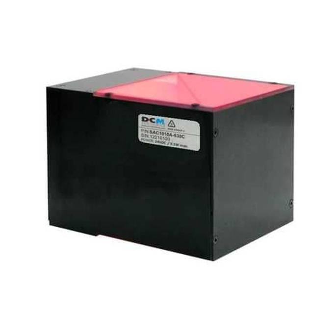
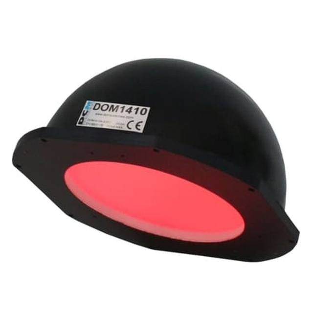
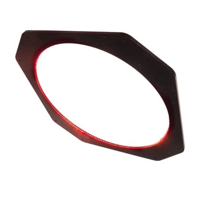
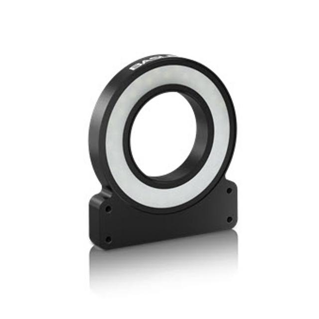
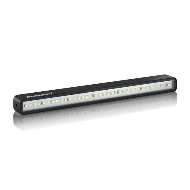
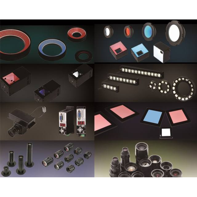
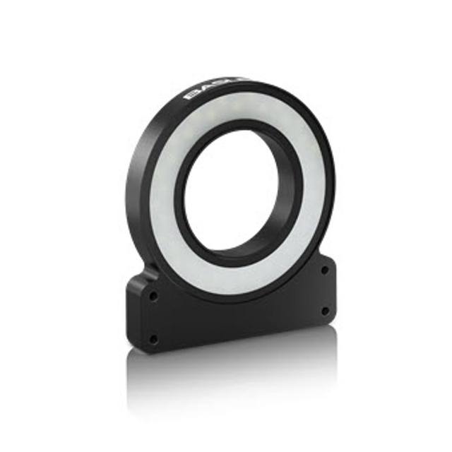
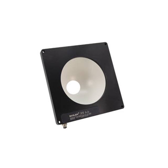
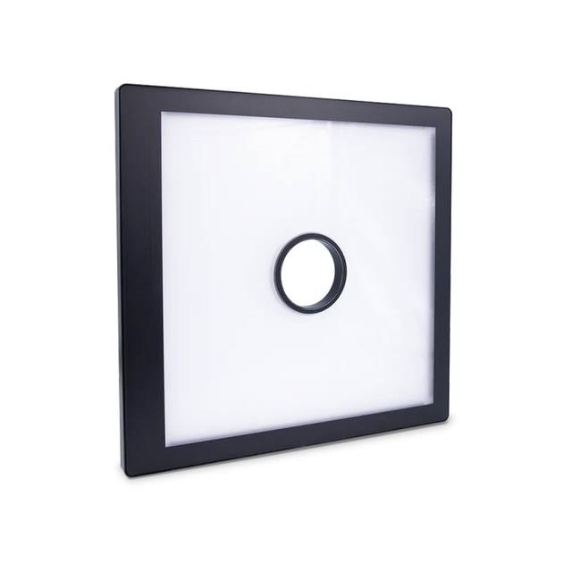
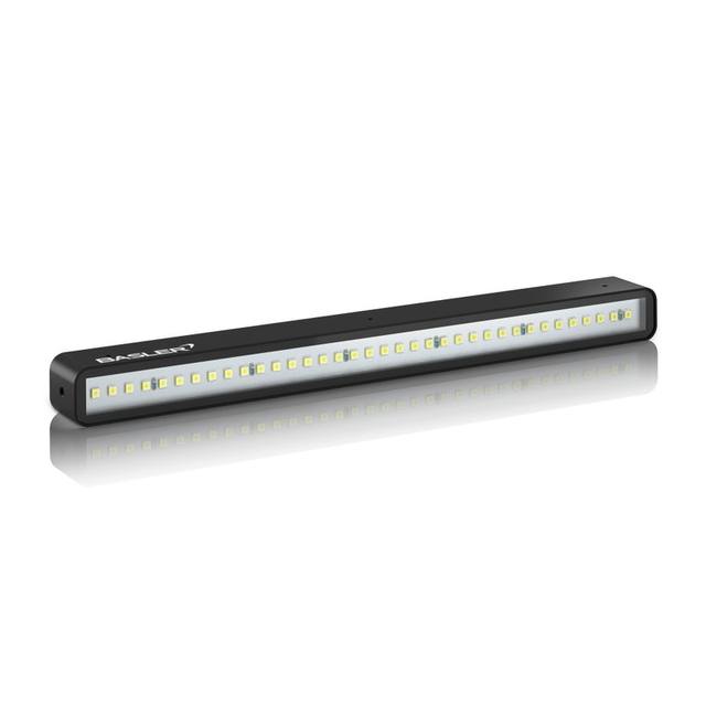
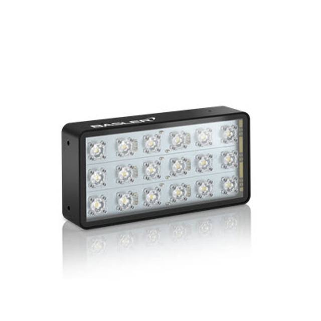
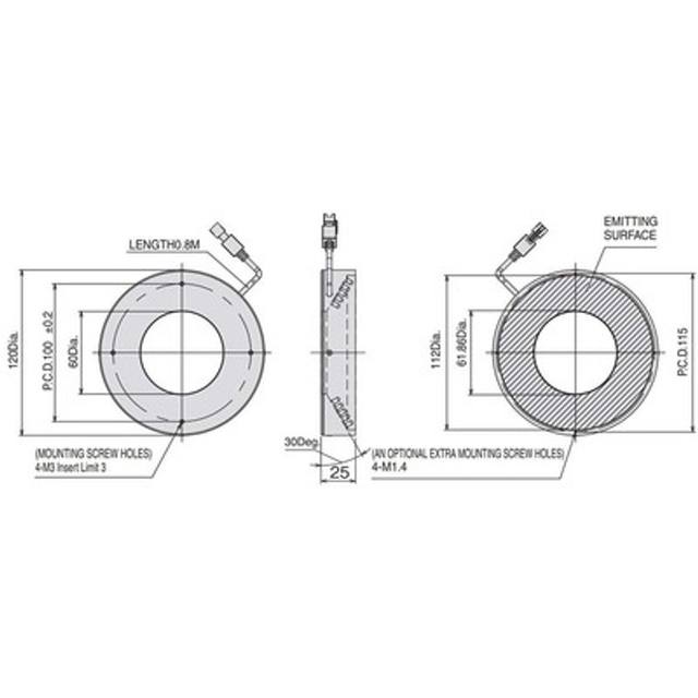
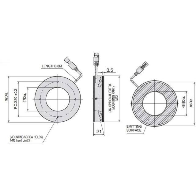
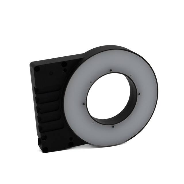
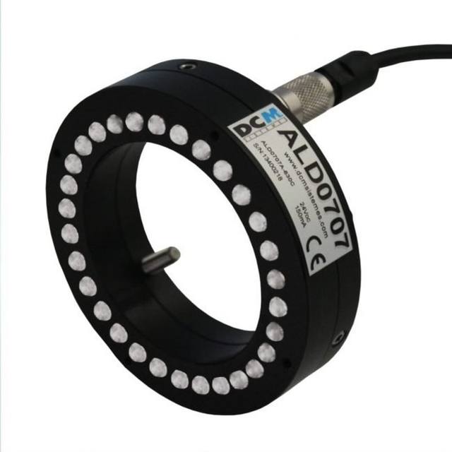
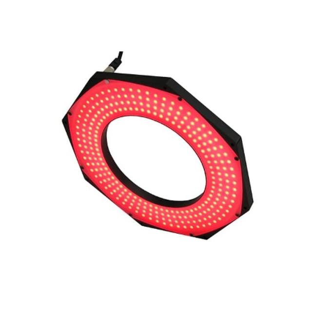
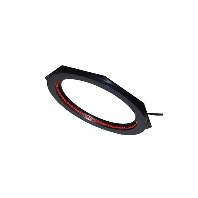
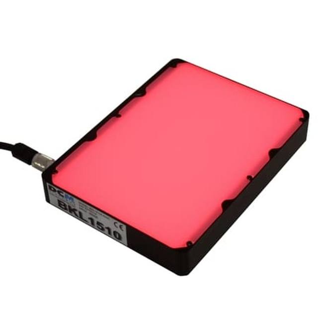
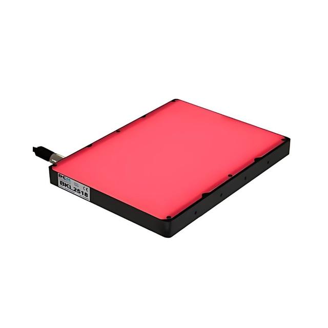
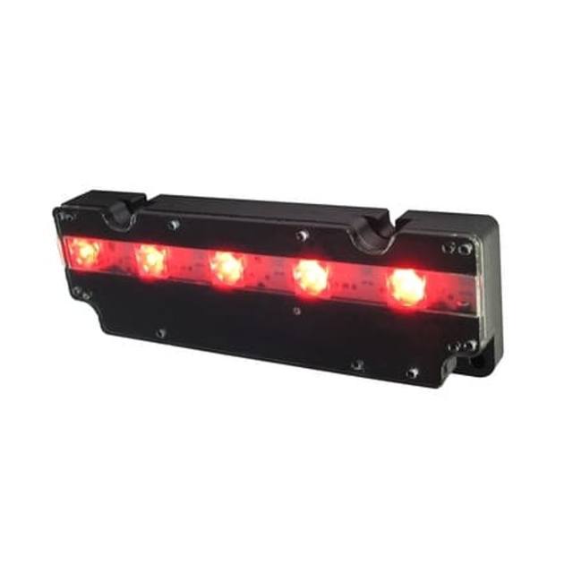
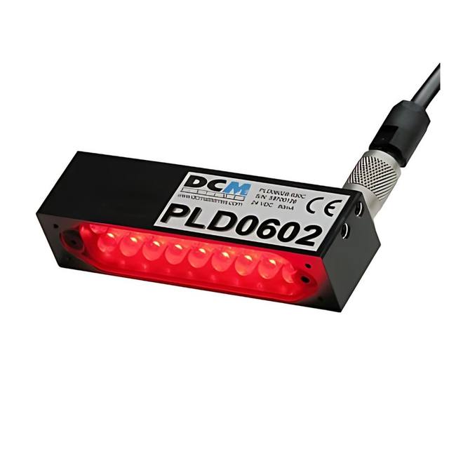
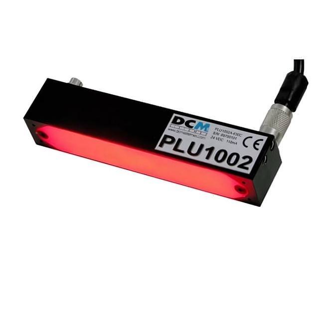
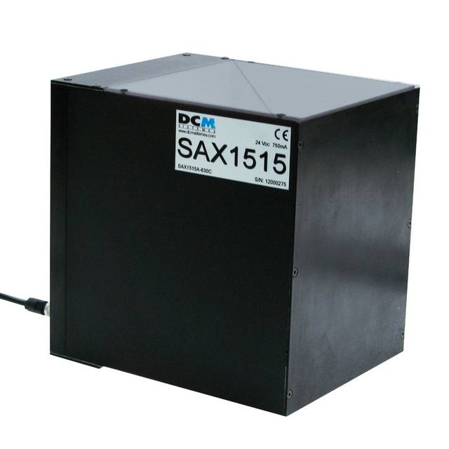
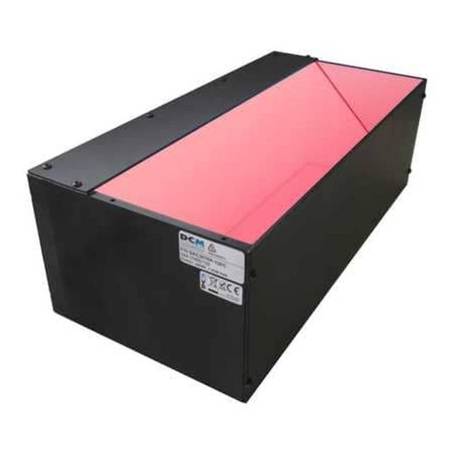
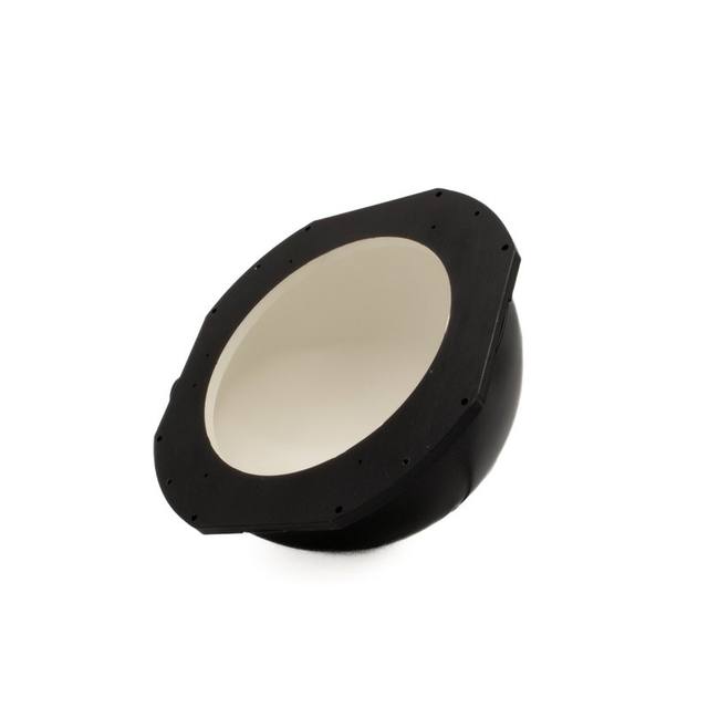
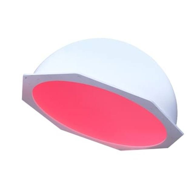
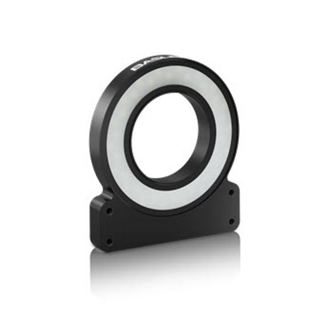
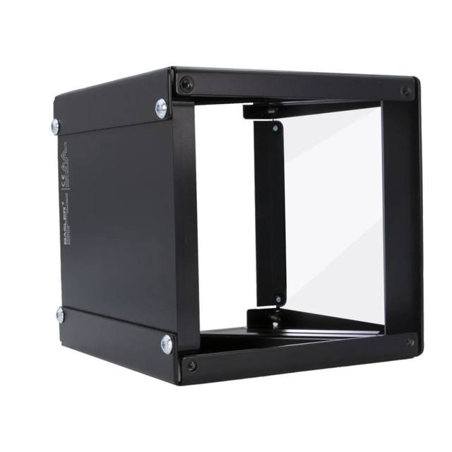
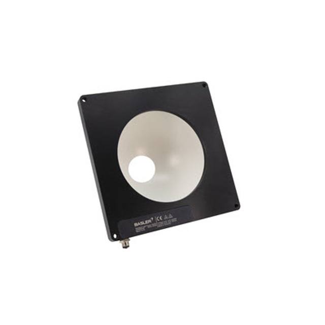
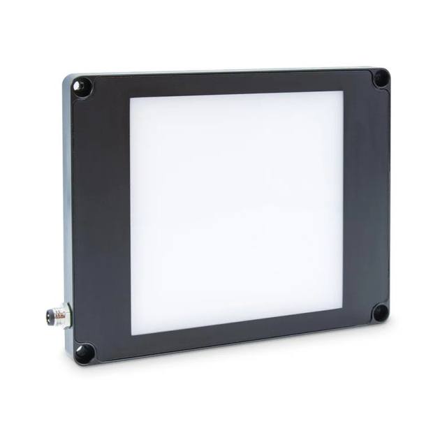
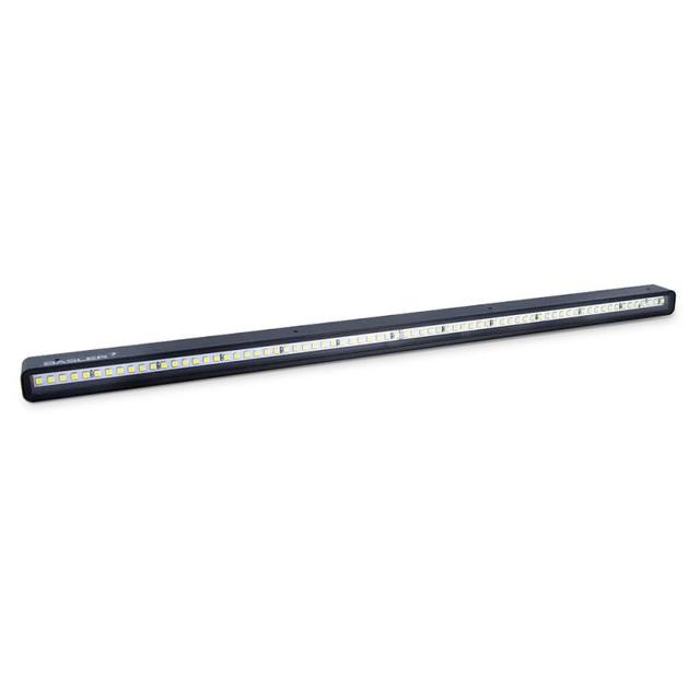
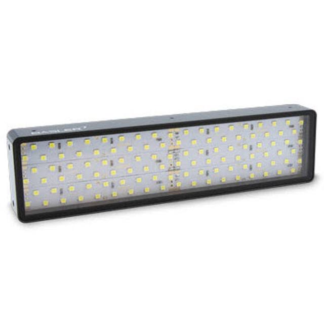
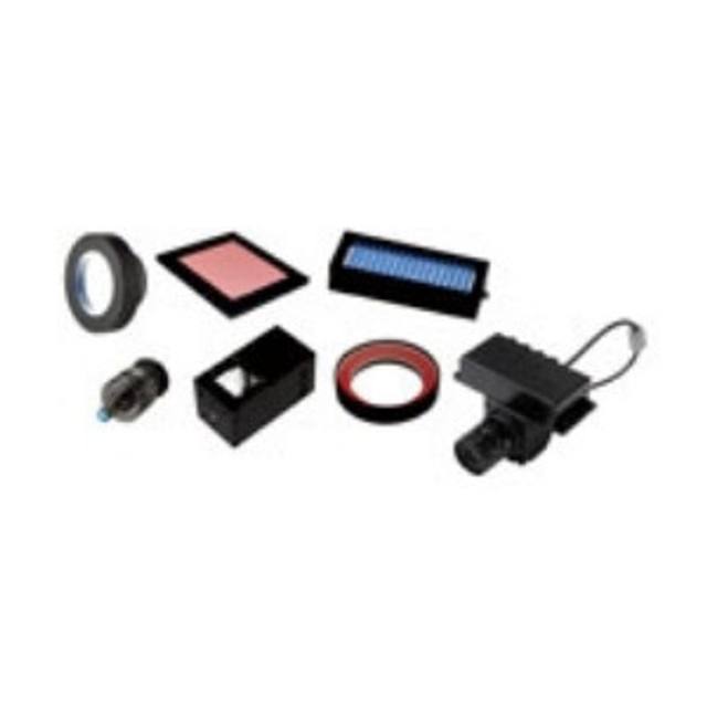
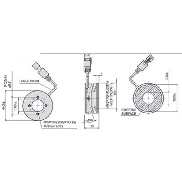
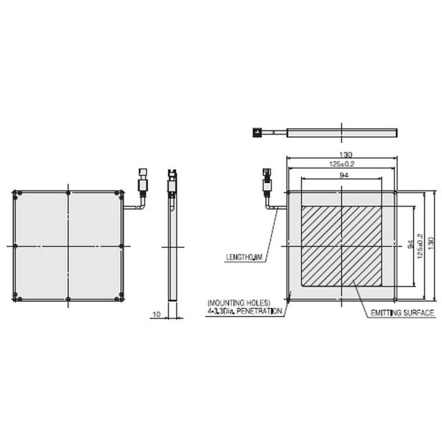
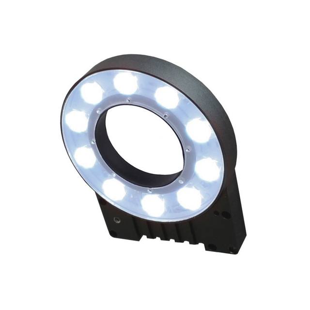
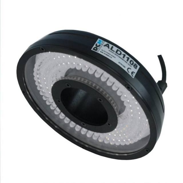
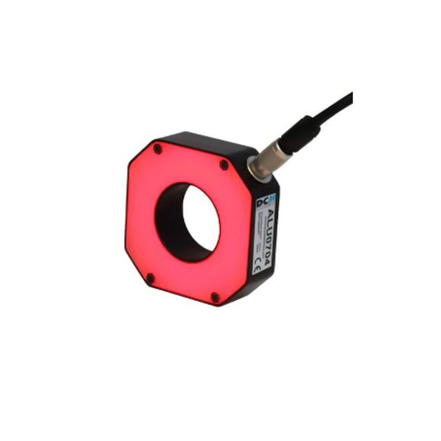
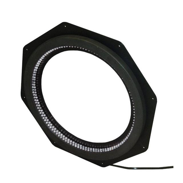
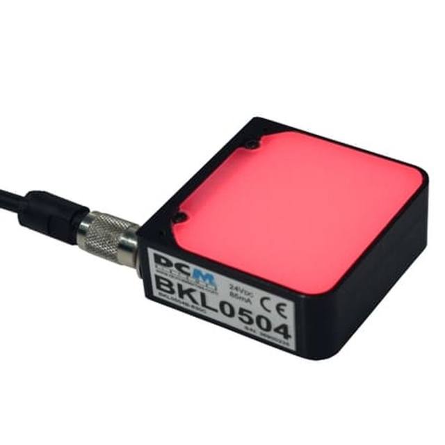
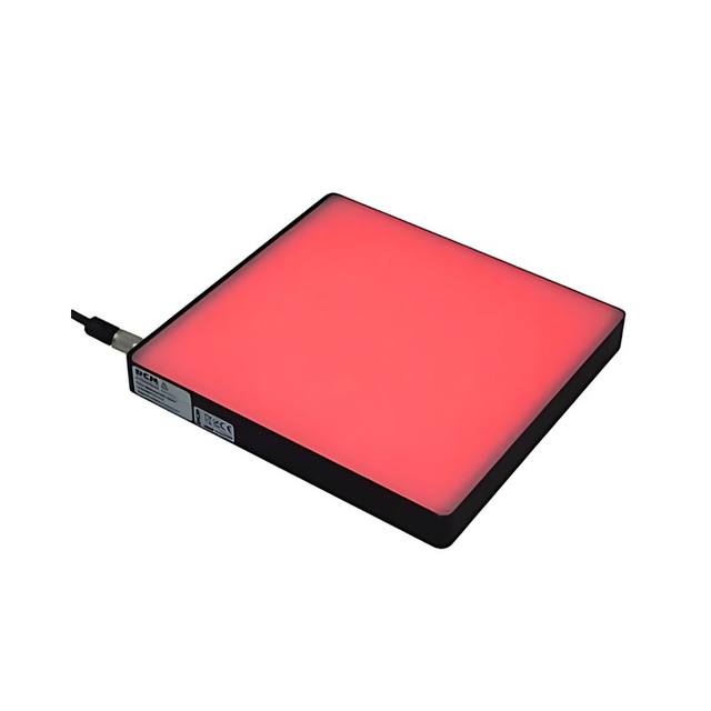
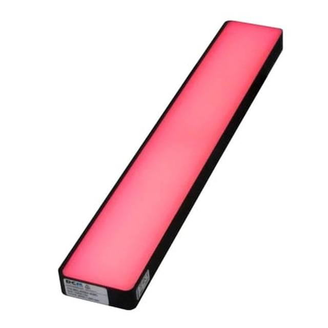
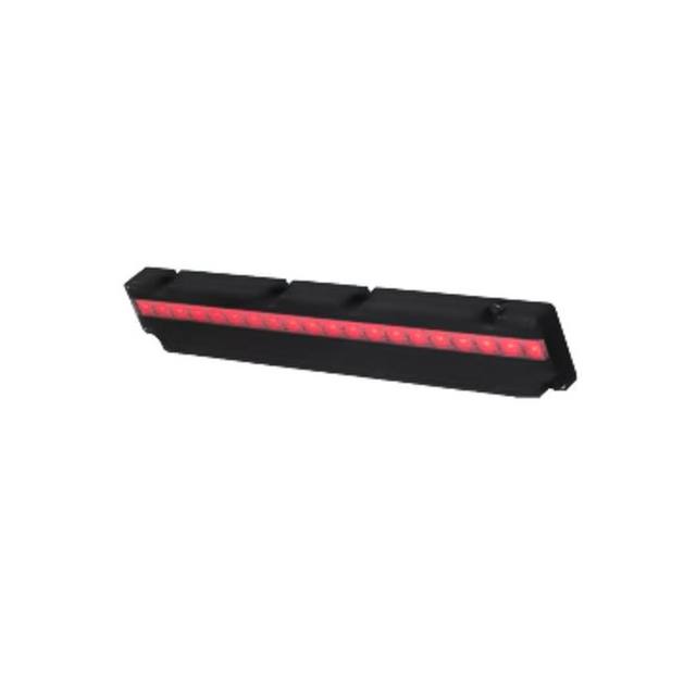
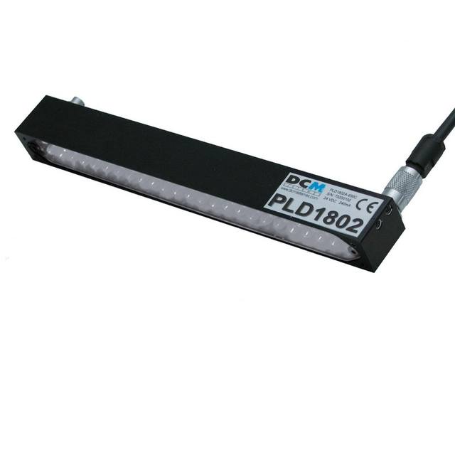
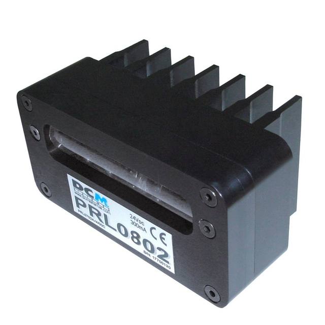
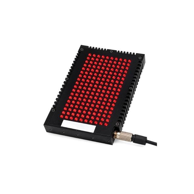
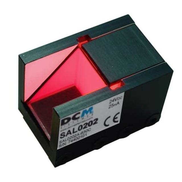
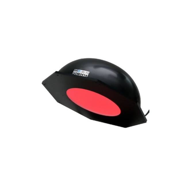
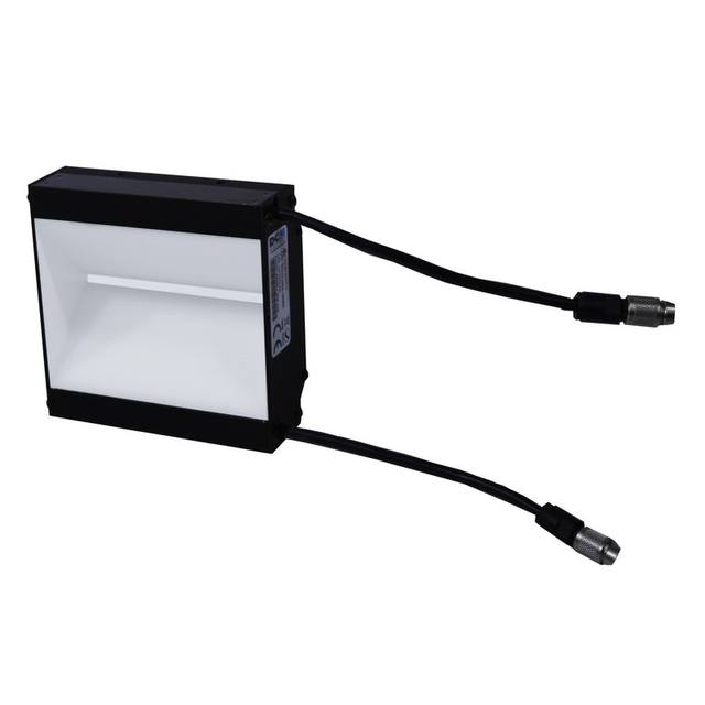
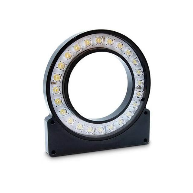
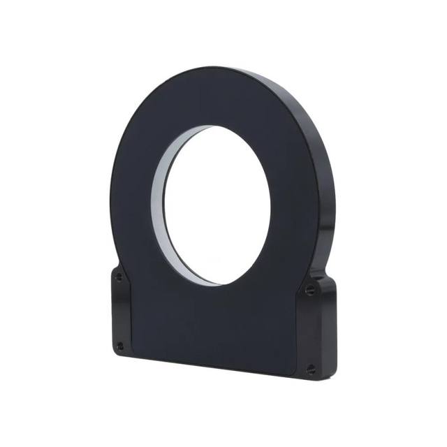
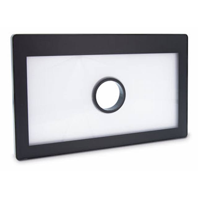
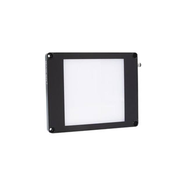
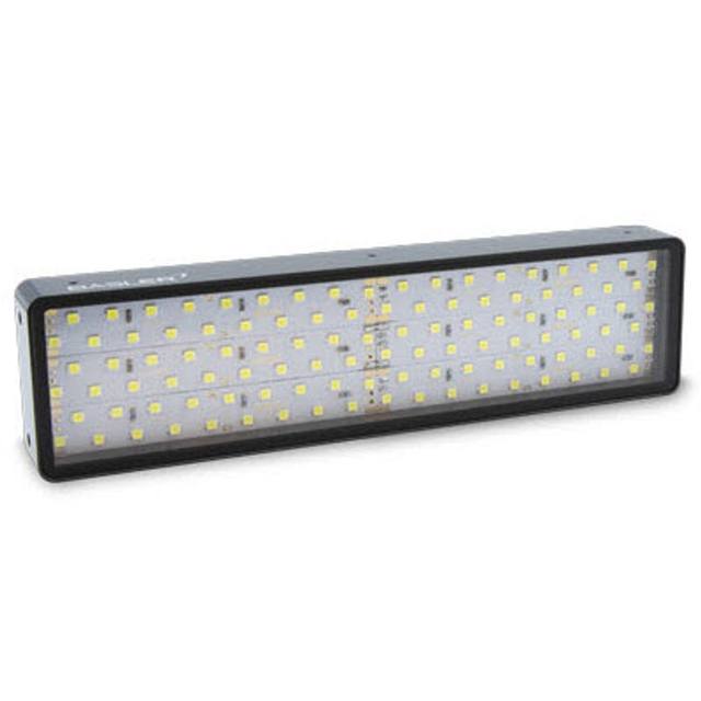
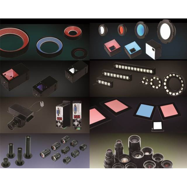
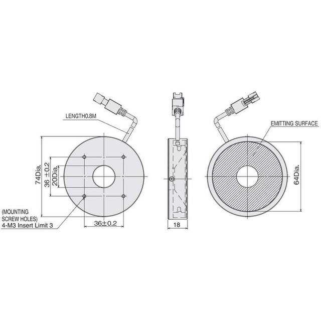
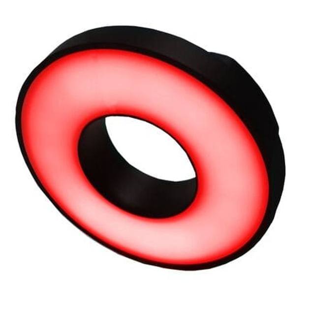
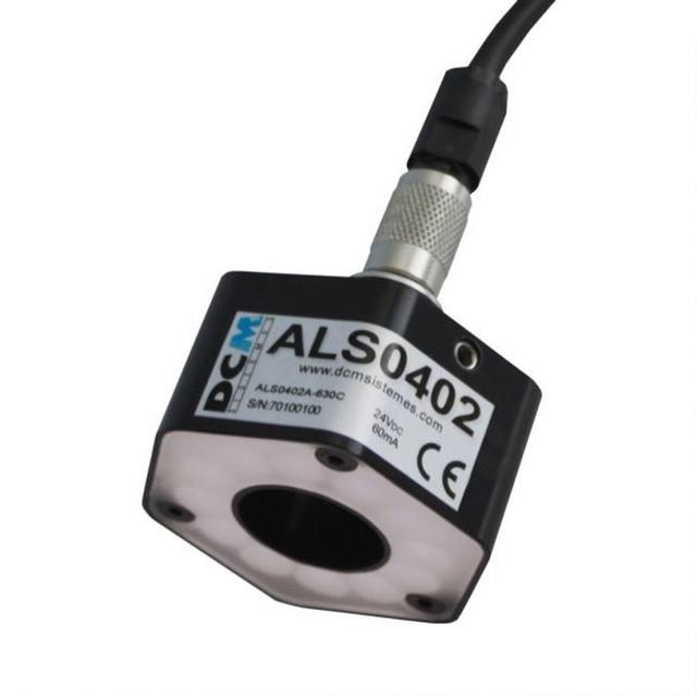
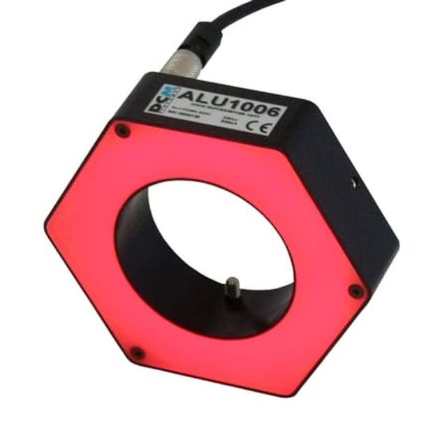
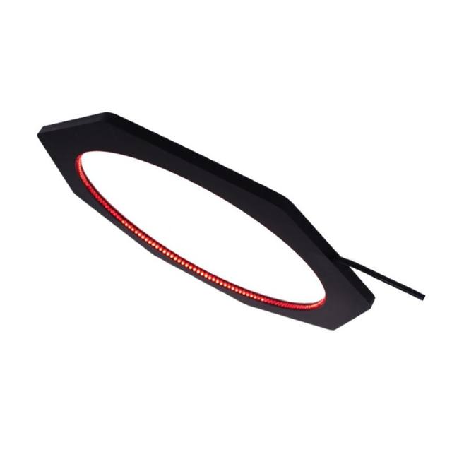
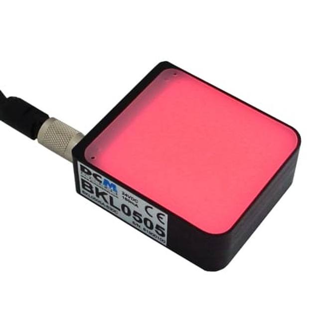
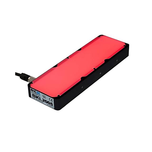
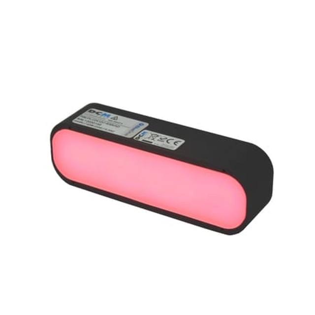
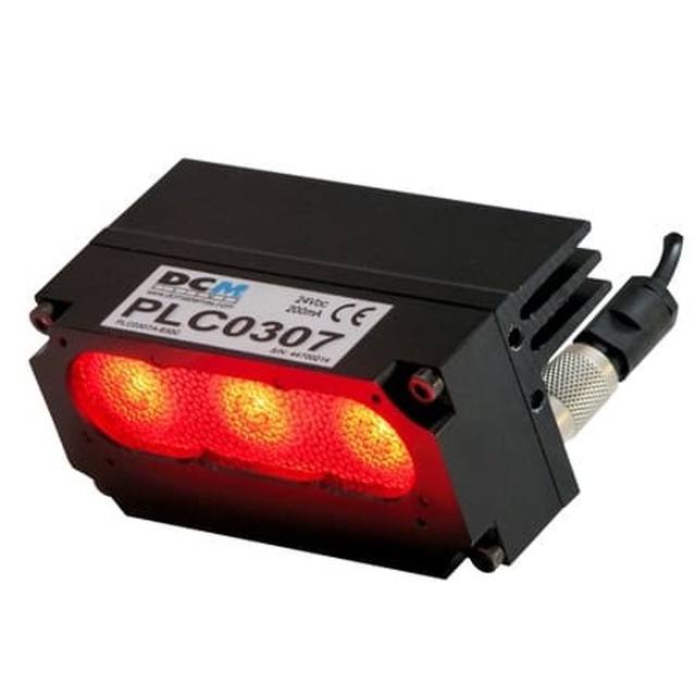
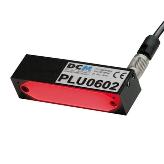
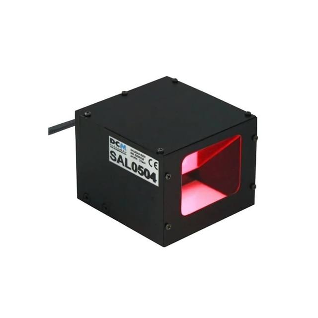
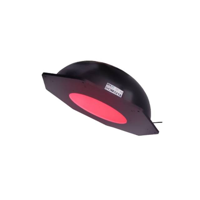
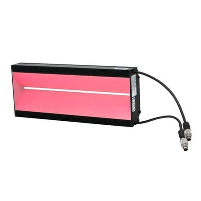
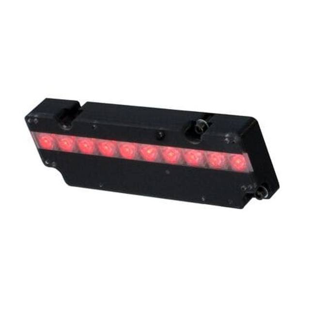
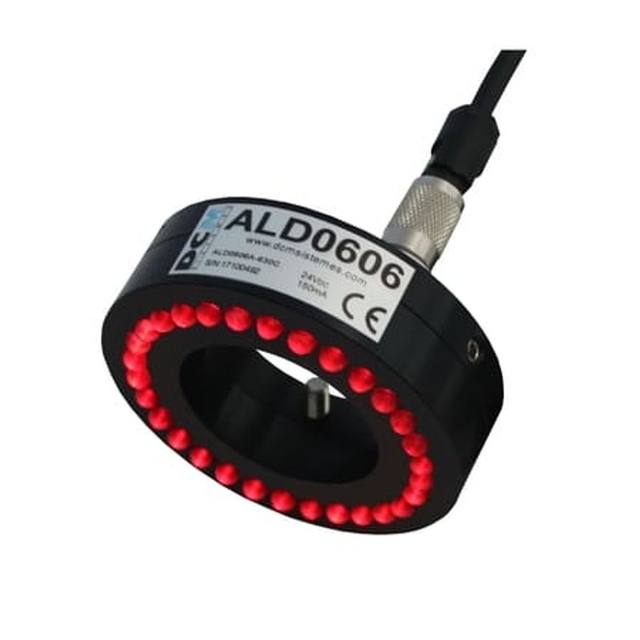
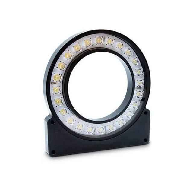
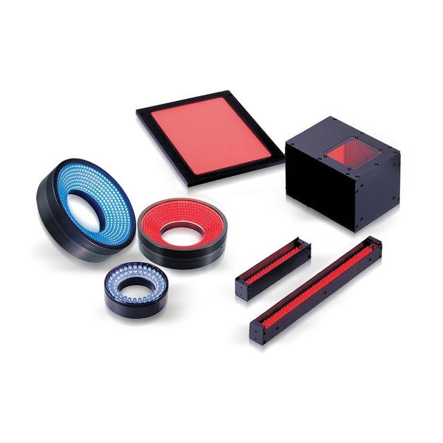
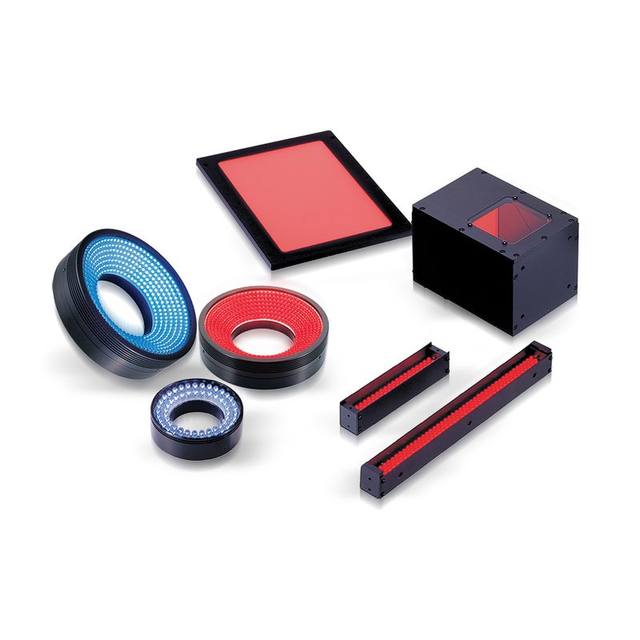
Lighting is not optional on a guidance cell; it is what makes the localisation repeatable. For 2D, controlled, diffuse illumination with strong feature contrast and a strobe synchronised to the trigger freezes any conveyor motion and removes ambient-light variation between shifts. For 3D, lighting interacts with the capture method: structured-light and stereo systems are sensitive to specular reflections from shiny metal and to deep shadows in a bin, so diffuse fill, controlled angles, and sometimes polarisation are used to tame glints that would otherwise punch holes in the point cloud. DCM Sistemes lighting can be specified to the geometry and the surface, which on guidance cells often determines whether the system sees every part or silently drops the awkward ones.
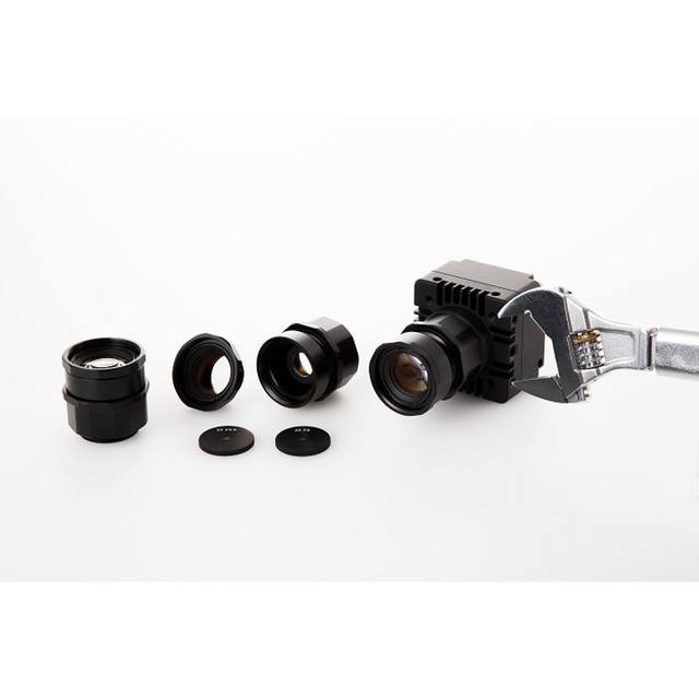
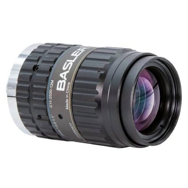
Around the sensor and lighting sit the unglamorous essentials: a rigid, repeatable camera mount; reliable triggering and timing so the image is captured at a known robot state; and a clean interface to the robot controller. Getting these right is what separates a demo from a cell that holds accuracy across a production year.
- 3D camera sized to the working volume, with depth noise and resolution well inside your pose tolerance plus calibration margin.
- Capture method matched to the scene: structured-light (accuracy, static), stereo (motion), time-of-flight (range/speed).
- 2D guidance: an area-scan camera (Basler, iRAYPLE, Omron/Sentech) over a flat, known-height plane.
- Synchronised, diffuse lighting (DCM Sistemes) sized to the geometry; manage specular glints and shadows for stable 3D clouds.
- A rigid, repeatable camera mount and deterministic triggering tied to robot state.
When deep learning earns its place
Classical geometry, edge and model matching against a CAD template, plane fitting, point-cloud registration, remains the right tool for well-defined, rigid parts with stable appearance, and it should be the default. It is deterministic, explainable and straightforward to validate against a calibration. Reach for deep learning when the scene defeats those assumptions: heavily cluttered bins, parts that are deformable, reflective or visually variable, or instance segmentation problems where the hard part is reliably separating one overlapping part from its neighbours before a pose is even estimated.
In those harder cases a learned model can identify graspable instances and candidate pick points where hand-tuned heuristics become brittle. Rosepetal, the group's deep-learning visual-inspection software, is relevant where that kind of robust detection and segmentation drives the pick, typically feeding pose estimation and the pick-point logic rather than replacing the geometric calibration. The pragmatic stance is hybrid: use AI for the perception that is genuinely hard to script, and keep the metric pose and hand-eye transform on a calibrated, verifiable geometric footing.