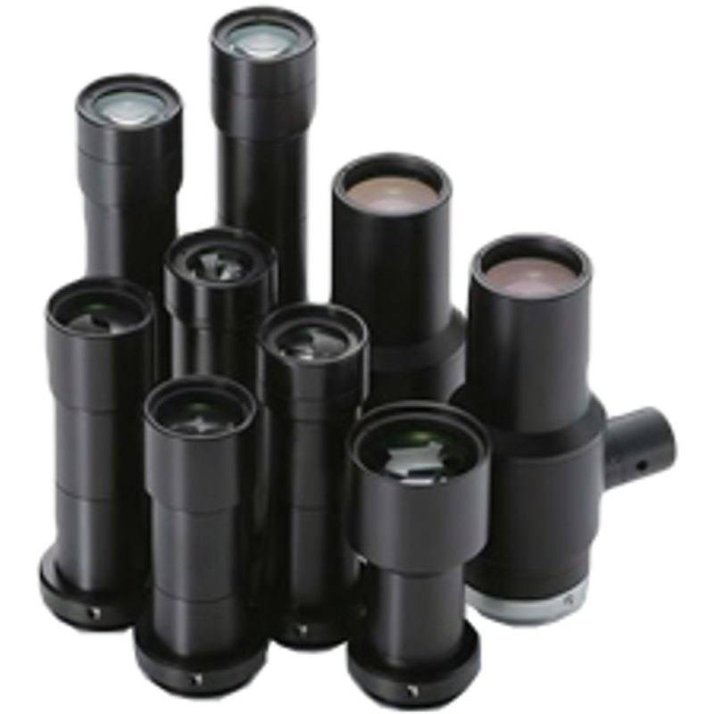
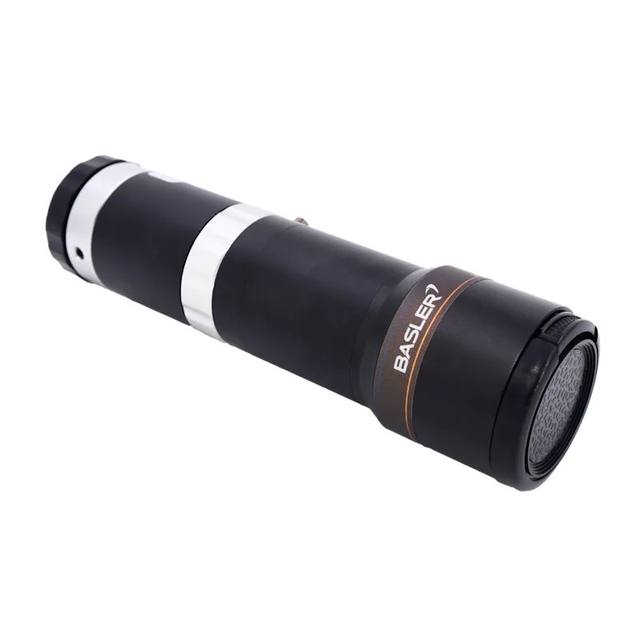
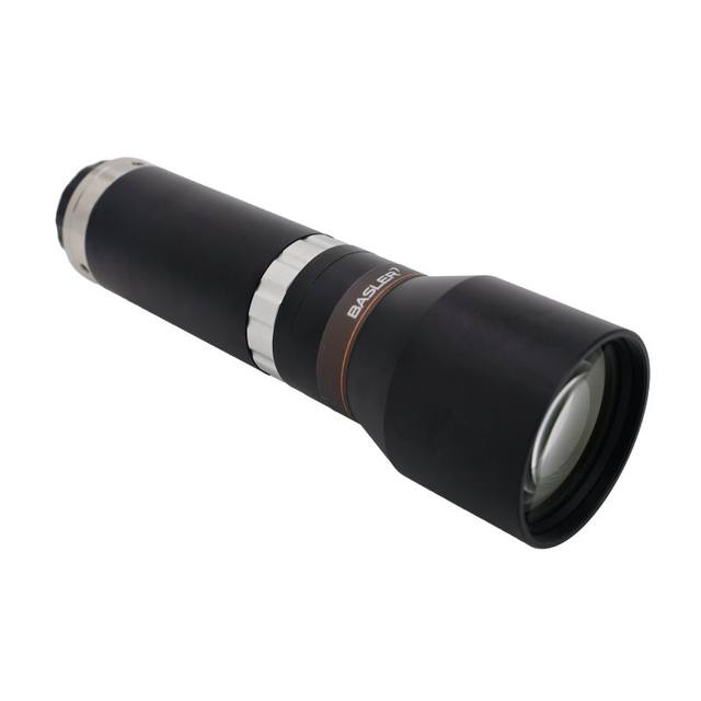
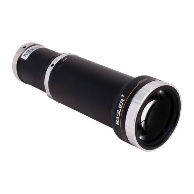
The VS-TCH2-110CO-O is part of Omron's 3Z4S-LE VS-TCH Series of high-resolution telecentric lenses for C-mount cameras. It delivers 2.0x magnification at a 110.8 mm working distance with an effective F-number of 13.5, 0.27 mm depth of field, and 4.53 μm optical resolution at 550 nm. The coaxial prism design accommodates coaxial illumination for shadow-free imaging of reflective surfaces. TV distortion is specified at a maximum of 0.03%, making it well-suited for dimensional measurement and precision alignment applications.
The Omron VS-TCH2-110CO-O is a fixed-magnification telecentric lens operating at exactly 2.0x, designed for C-mount megapixel cameras with sensors up to the 2/3-inch format. Telecentricity is the defining optical property here: unlike conventional lenses, the chief ray exits the lens parallel to the optical axis, which means the apparent size of an object does not change with small depth variations. This makes the lens fundamentally different from entocentric alternatives for any application where a measured dimension must be independent of part height variation or focus drift. The TV distortion figure of 0.03% maximum is consistent with sub-pixel dimensional measurement at 2.0x magnification, enabling reliable gauging of precision-machined parts, connector pins, or pharmaceutical tablet profiles.
The coaxial prism design built into the lens body is the other distinguishing feature. Coaxial illumination — where light travels along the same axis as the imaging path — produces near-specular, shadow-free images of flat or mirror-like surfaces: bare silicon dies, polished metal lands, solder pads, and glass substrates that scatter or absorb oblique ring-light poorly. Because the coaxial port is integrated rather than added externally, the working distance of 110.8 mm (±3.3 mm tolerance) is fixed by the optic itself and must be respected at installation; there is no focus adjustment to compensate for changes in object distance outside that tolerance. The effective aperture of F/13.5 and the resulting 0.27 mm depth of field are direct consequences of telecentric design at 2.0x — installers should account for part height variation falling within that depth budget or plan for axial stages. Optical resolution is quoted at 4.53 µm at 550 nm wavelength, so pixel pitch on the chosen sensor should be at or below roughly 4–5 µm to fully exploit the lens's resolving capability without wasting optical performance.
The lens mounts directly to any C-mount camera body and covers sensors up to 2/3 inch, covering the most common high-resolution area-scan formats used in precision inspection. At 110 g the lens is mechanically modest and integrates without excessive cantilever stress on camera PCB connectors. The operating temperature range of 0–50°C is standard industrial range. Because the working distance is non-adjustable, system integrators must dimension mounting fixtures with precision: the 110.8 mm standoff from the front element to the object plane is the only valid working position, and any compliance in the fixture will erode measurement repeatability. Coaxial light source selection should prioritize narrow-spectrum illumination near 550 nm to match the specified optical resolution wavelength, though the coaxial port can accept broadband sources where color discrimination is not needed.
Best for
Dimensional gauging of precision-machined or stamped metal parts where sub-pixel accuracy is required and part height variation must not introduce magnification error — telecentricity directly eliminates perspective error that would otherwise corrupt edge-detection-based measurements.
Semiconductor and electronics inspection of flat reflective surfaces such as bare die, bond pads, BGA lands, and PCB solder joints, where the integrated coaxial illumination port produces shadow-free, high-contrast images that oblique or ring lighting cannot achieve on specular targets.
Pharmaceutical tablet and capsule dimensional verification on conveyored lines, where consistent 2.0x magnification and low distortion enable reliable pass/fail decisions on diameter, thickness, and edge profile without per-part recalibration.
Precision alignment and robot guidance tasks requiring a known, repeatable magnification factor so that pixel-to-millimeter calibration remains stable over time and across units, reducing inline calibration overhead.
Connector and fine-pitch component inspection in electronics assembly where the coaxial illumination reveals surface-height discontinuities and co-planarity defects on reflective leads or terminals that would otherwise produce glare artifacts under directional lighting.
Selection notes
The 110.8 mm working distance is fixed and non-adjustable — design the fixture or gantry to hold this standoff precisely. Even small deviations will shift the object plane outside the 0.27 mm depth of field and degrade resolution to below the 4.53 µm specification, which will manifest as blurred edges and poor measurement repeatability.
Sensor format must not exceed 2/3 inch. Mounting this lens on a camera with a larger sensor will produce darkened corners and invalid measurements outside the specified image circle — verify sensor size of the target camera before specifying.
The F/13.5 effective aperture limits light throughput compared to lower-f-number entocentric lenses. Coaxial illuminators must provide sufficient radiance to achieve the exposure times compatible with line speed; strobed high-intensity coaxial sources are typically preferred over continuous low-power LEDs for moving parts.
Pixel pitch on the mated camera should ideally be 4–5 µm or smaller to avoid undersampling the 4.53 µm optical resolution limit. Using a sensor with coarser pixels wastes the lens's resolving capability and limits the minimum detectable feature size, while much finer pixels provide no additional sharpness benefit given the optical resolution floor.
The 0.03% TV distortion specification applies at the rated working distance and for sensors within the 2/3-inch image circle. Any field-flattening or calibration routine in the vision software should use a certified calibration target measured at the exact working distance to validate this distortion baseline before going into production measurement mode.
Specifications: General
Brand
Omron / Sentech
Specifications: Optical
Lens mount
C-Mount
Magnification
2.0x
Working distance
110.8 mm (±3.3 mm)
Aperture (f-number)
F/13.5 (effective)
Image circle / max sensor
2/3 inch (max)
Telecentric
Yes
Focal length
Not specified (telecentric design)
Specifications: Environment
Operating temperature
0 to 50°C
Specifications: Mechanical
Weight
110 g
Applications this camera is commonly selected for. Open one to see the full recommended hardware and approach.
Matched automatically by: camera mount fits the lens mount · camera sensor is covered by the lens image circle — this lens: C-Mount · 2/3 inch (max) image circle.
By category
All 758Area scan cameras 622High-speed cameras 108High-resolution cameras 28
By brand
All 758Omron / Sentech 297Basler 242iRAYPLE 200Datalogic / Datasensing 19
These steps take an Omron Sentech (STC) camera from the box to a stable first image and on to your own application. They apply across the GigE Vision, USB3 Vision and CoaXPress STC families; the interface only changes how you cable and power the camera.
Download and install the Sentech SDK on the host PC. The package provides StViewer, the viewing and configuration software you use to bring the camera up, and StApi, the programming SDK you integrate later. Because the cameras are GenICam/GenTL-compliant, StApi also registers a GenTL producer, so any GenICam-compliant third-party vision software can discover and drive the camera as an alternative front end.
2. Cable, power and connect the camera
Connect according to the interface. GigE Vision: link to a Gigabit NIC (use PoE or the separate power input) and put the camera and host on the same subnet; for USB3 Vision use a USB 3.x port and a certified cable; for CoaXPress (STC) connect to a CoaXPress frame grabber, which also supplies Power-over-Coax. Then open StViewer and let it enumerate the camera. If a GigE camera does not appear, check the IP configuration and firewall, and on USB3 confirm the host bandwidth and driver.
3. Configure exposure, gain and white balance
Open the device in StViewer and start a live stream. Set exposure and gain for a well-exposed, low-noise image: raise exposure first and only add gain when more light or a faster shutter is not an option, keeping exposure short enough to freeze motion on global-shutter models. On colour cameras, run white balance under your actual production lighting. Adjust the lens aperture and focus on a representative target before tuning anything else.
4. Set the trigger and grab a first image
Start in free-run (continuous) acquisition to confirm a clean, stable image. For inline inspection switch to hardware or software triggering: select the trigger source, set the active edge and any delay, and wire the strobe or illumination to the camera's I/O so lighting fires with each exposure. Acquire and save a frame in StViewer; this saved image is your reference for the SDK stage and for downstream inspection.
5. Move to the StApi SDK (or any GenICam software)
Once the image is stable, reproduce the same settings in code. Use StApi to open the device, apply the GenICam features you validated in StViewer (exposure, gain, trigger, pixel format) and grab frames into your application via the bundled C++, C, C#/.NET or Python interfaces; the included samples are the fastest starting point. Prefer a different stack? The same GenICam/GenTL camera works with third-party vision libraries. With a reliable feed, you can route it into a deep-learning inspection such as Rosepetal for AI-based defect detection.
Frequently asked questions
The working distance is 110.8 mm with a stated tolerance of ±3.3 mm. The depth of field at F/13.5 is only 0.27 mm, so while the mechanical mounting tolerance allows up to 3.3 mm of assembly variation, any object height variation within a part or between parts must stay within the 0.27 mm depth-of-field window to maintain the rated optical resolution of 4.53 µm.
The lens is specified for sensors up to 2/3 inch maximum image circle, on a C-mount camera body. Sensors larger than 2/3 inch will show vignetting at the corners and should not be used with this lens.
Yes — the VS-TCH2-110CO-O is a coaxial-type telecentric lens with an integrated prism that accepts coaxial illumination. The lens does not include a light source; an external coaxial illuminator must be connected to the coaxial port on the lens body. Sources emitting near 550 nm wavelength are optimal for matching the specified 4.53 µm optical resolution, though other wavelengths can be used where color is not critical.
TV distortion is specified at a maximum of 0.03%, which is among the lowest available for any machine vision lens and is considered adequate for sub-pixel dimensional measurement applications. At 2.0x magnification this figure makes the lens suitable for precision gauging of small mechanical components, semiconductor features, and pharmaceutical dosage forms.
The lens is physically a C-mount optic and can be mounted on any compatible camera regardless of illumination choice, but its coaxial prism design is specifically optimized for coaxial illumination. Using ring or dome lighting on reflective targets will produce the same glare and shadow artifacts seen with any other lens — the optical and measurement benefits of this lens on specular surfaces are realized only when paired with a coaxial illumination source through the integrated port.