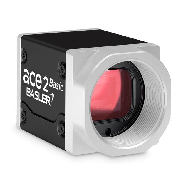
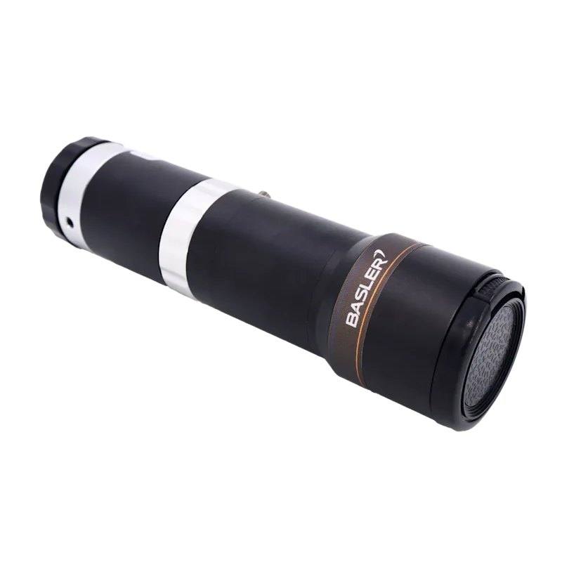
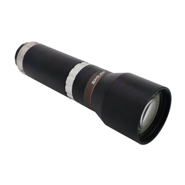
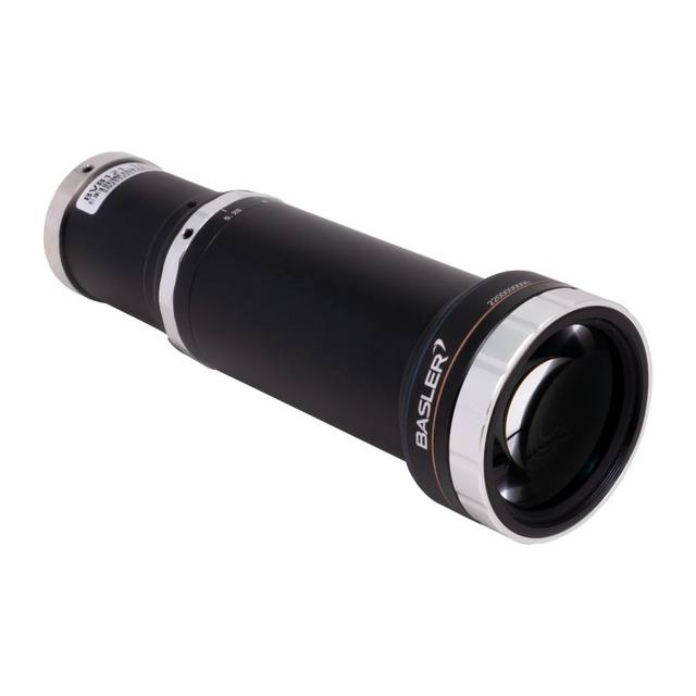
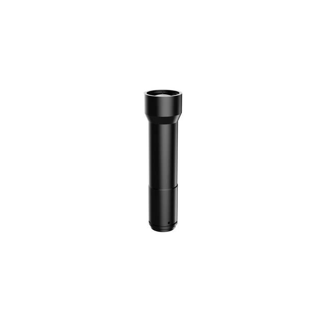
The Basler C23T-1-110-VI is a single-sided telecentric lens with a fixed 1.0x magnification, providing perspective-distortion-free imaging for dimensional measurement and inspection. It features a variable iris with an aperture range of F7–F32 and covers a 2/3" sensor format (11 mm image circle) via a C-mount interface. The lens delivers extremely low distortion (0.035% max typical) and object-side telecentricity of 0.04° max, with a working distance of 108 ±2 mm and a total length of 105.1 mm. Theoretical object-side resolution ranges from 4.7 µm at F7 to 21.0 µm at F32, with an operational wavelength range of 400–700 nm.
The Basler C23T-1-110-VI is an object-side telecentric C-mount lens operating at a fixed 1.0x magnification with a working distance of 108 ±2 mm. Telecentricity is the defining characteristic for any application that requires dimensional accuracy: because the chief rays travel parallel to the optical axis on the object side, features at different heights in the scene are imaged at the same magnification — no perspective foreshortening, no apparent size change caused by small part-to-lens distance variation. With a maximum telecentric angle of 0.04°, the lens holds this property extremely tightly across the entire 11 mm image circle, making it suitable for traceable gauging tasks where sub-pixel repeatability is expected.
The variable iris spans F7 to F32, giving the installer a meaningful trade-off between diffraction and depth of field. At F7 the theoretical object-side resolution is 4.7 µm. Stopping down to F32 relaxes resolution to 21.0 µm but deepens the in-focus band, which can be advantageous when parts have height variation or when the mechanical fixture is less precise. The 400–700 nm operational wavelength range covers the full visible spectrum, so the lens works with white, red, green, or blue LED illumination without chromatic concerns; switching illumination colour to improve contrast on different materials does not require refocusing or recalibration.
The C-mount interface and 11 mm (2/3") image circle make the lens directly compatible with the broad range of 2/3" area-scan cameras using C-mount. The 105.1 mm total length and 108 mm working distance define a compact, fixed-geometry inspection cell: the part sits roughly 108 mm from the front of the lens, and the total back-to-front envelope from sensor to object is well under 250 mm, fitting comfortably inside benchtop gauging fixtures or inline conveyor stations. Because the working distance is fixed and the magnification is 1.0x, the field of view is determined entirely by the sensor dimensions — the object-plane field of view equals the sensor active area exactly, and one pixel corresponds to one pixel-pitch of object distance, a predictable relationship that simplifies calibration and system documentation.
Best for
Dimensional gauging of machined or stamped parts where height variation across the part would cause measurement error with a conventional lens — the 0.04° telecentric angle eliminates parallax-induced size error across the full 11 mm image circle.
Semiconductor and electronics component inspection — die placement, solder joint width measurement — where the 4.7 µm object-side resolution at F7 resolves fine features and 1.0x magnification gives a direct pixel-to-object calibration constant.
Pharmaceutical blister-pack and tablet dimensional verification on a conveyor, where the fixed 108 mm working distance and telecentric projection allow accurate diameter and gap measurements without sensitivity to minor part-to-lens distance drift caused by vibration.
Automotive precision parts and medical-device component inspection requiring very low distortion — the 0.035% maximum distortion figure ensures that measured feature positions across the image corners are not corrupted by lens geometric error.
Packaging print and feature inspection tasks that also require dimensional conformance checks, where a single imaging station must perform both appearance and measurement roles on a 2/3" sensor camera already installed in the line.
Selection notes
Sensor format must not exceed 2/3" (11 mm image circle): using this lens on a larger sensor will result in vignetting at the image corners and invalidate the telecentric projection outside the specified circle. Confirm the camera's active sensor diagonal before ordering.
The working distance is fixed at 108 ±2 mm with no focus adjustment — the part must be positioned within ±2 mm of the nominal standoff. Design the fixture or conveyor stop to hold this tolerance; the telecentric advantage is lost if parts sit significantly outside this band.
Choose aperture based on part height variation and required resolution: F7 gives 4.7 µm object-side resolution for fine feature work on flat parts; F22–F32 trades resolution for greater depth of field when parts have steps or height variation up to several millimetres.
The 400–700 nm wavelength range is compatible with all common visible LED illumination colours. Coaxial or on-axis diffuse illumination is the standard pairing for telecentric lenses because it preserves the parallel-ray geometry; ring lights at steep angles can introduce artefacts at part edges and should be evaluated carefully.
At 1.0x magnification the field of view equals the sensor active area: the object-plane dimensions match the sensor dimensions exactly, so verify that the sensor active area covers the largest part feature to be measured before finalising the camera selection.
Specifications: General
Brand
Basler
Specifications: Optical
Lens mount
C-mount
Magnification
1.0x
Working distance
108 ±2 mm
Aperture (f-number)
F7–F32
Image circle / max sensor
11 mm (2/3" format)
Telecentric
Yes (object-side telecentric)
Optical resolution
4.7–21.0 µm object-side resolution
Applications this camera is commonly selected for. Open one to see the full recommended hardware and approach.
Matched automatically by: camera mount fits the lens mount · camera sensor is covered by the lens image circle — this lens: C-mount · 11 mm (2/3" format) image circle.
By category
All 758Area scan cameras 622High-speed cameras 108High-resolution cameras 28
By brand
All 758Omron / Sentech 297Basler 242iRAYPLE 200Datalogic / Datasensing 19
Get a first image quickly with the pylon Viewer, then move into the pylon SDK for your application. These cameras are GenICam/GenTL-compliant, so any compliant vision software can drive them as well.
Download and install the pylon Camera Software Suite for your OS from Basler. This provides the pylon Viewer, the GenTL transport-layer producers and the pylon SDK (C/C++/.NET/Python). On Windows the installer adds the needed drivers; on Linux follow the included setup notes for USB and network permissions.
2. Connect the camera and check the link
Cable the camera to its matching interface: GigE Vision to a GigE port (use a quality cable and, ideally, a dedicated NIC with jumbo frames enabled), USB3 Vision to a USB 3.x port with the supplied cable, or CoaXPress to the frame grabber. Provide power where required (PoE, USB bus power, or PoCXP). Open the pylon Viewer and confirm the camera appears in the device list; for GigE, make sure the camera and NIC are on the same subnet.
3. Grab a first image and set exposure, gain and pixel format
Select the camera in the pylon Viewer and start a continuous grab. Adjust exposure time and gain until the image is well exposed (avoid clipped highlights), set the pixel format (e.g. Mono8 or a Bayer/RGB format), and focus the lens. Use a test pattern if the lens or scene is not ready yet.
4. Configure triggering and acquisition
Decide between free-run and triggered acquisition. For synchronized capture, set the trigger source (software or a hardware line on the I/O connector), trigger mode and any debounce or exposure mode, then verify timing. Note the parameter names you change in the Viewer feature tree, as you will reuse them in code.
5. Move to the SDK or a GenICam-compliant library
Recreate your settings in code with the pylon SDK (C, C++, .NET or Python) to open the device, apply the same features and pull frames into your pipeline; pylon vTools and pylon AI can add processing blocks. Because the cameras are GenICam/GenTL standard, third-party vision libraries work too. Once the image stream is stable, you can route frames to a deep-learning inspection such as Rosepetal for automated defect detection.
Frequently asked questions
Because the magnification is fixed at 1.0x, the field of view in the object plane equals the camera sensor's active area exactly. No scaling calculation is needed — one sensor pixel corresponds to one pixel-pitch of object distance. Consult your camera's datasheet for its active area dimensions to determine the resulting field of view.
No. The lens has a fixed focal design with a working distance of 108 ±2 mm. There is no focus ring. The part must be positioned within the ±2 mm tolerance band. If your application requires a different working distance, a different telecentric lens model must be selected.
At 0.035% maximum distortion across the 11 mm image circle, geometric error at the image periphery is extremely small — well below the 4.7 µm resolution limit at F7. In practical terms, no software distortion correction is required for most gauging applications.
Yes. The operational wavelength range of 400–700 nm covers the full visible spectrum. The lens works with both monochrome and colour (Bayer-pattern) 2/3" C-mount cameras. Monochrome sensors remain the safer choice for the highest-accuracy dimensional work as they avoid demosaicing artefacts.
F7 provides the finest object-side resolution (4.7 µm) and is the best starting point for flat parts with minimal height variation. Stopping down improves depth of field — at F32 the resolution relaxes to 21.0 µm but the in-focus zone deepens, which helps when parts have steps or are not perfectly flat. Choose the most open aperture that keeps all critical features acceptably sharp.