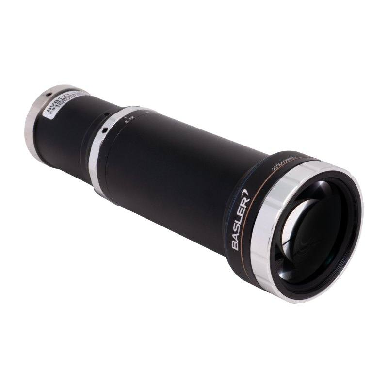
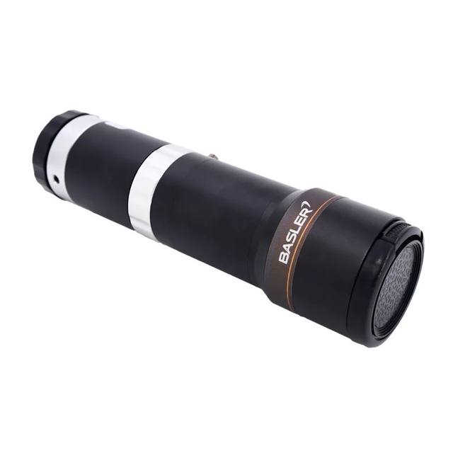
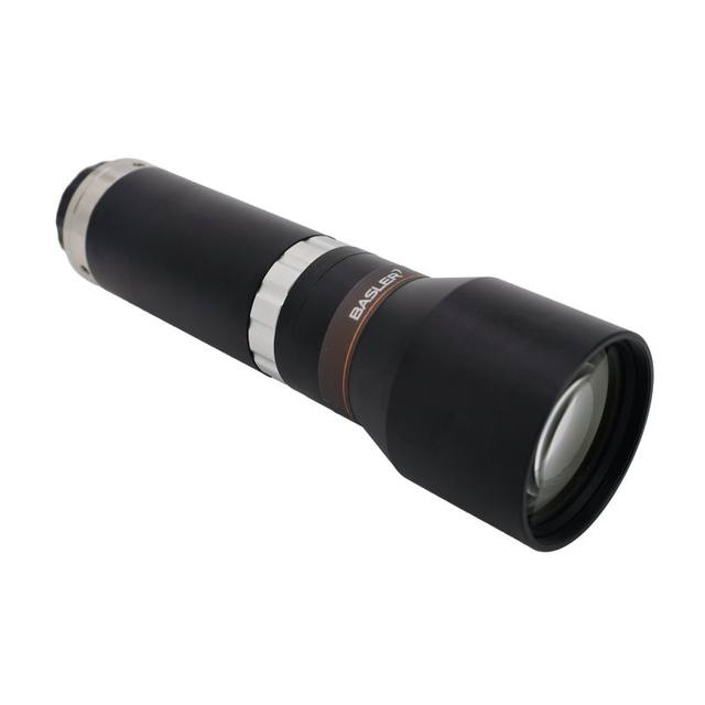
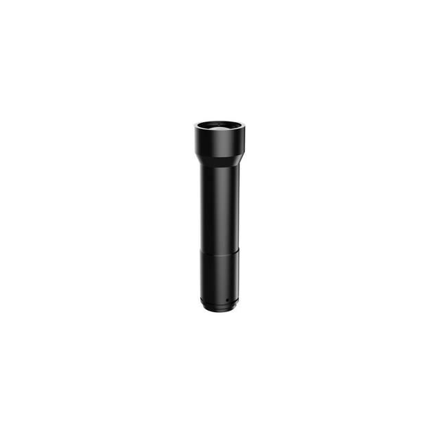
The Basler C12T-1-80-VI is a bi-telecentric machine vision lens with a fixed 1.0x magnification and 80 mm working distance, designed for Basler cameras with sensors up to 1.2" (20 mm image circle). It features an aperture range of F5.3–F32 with a theoretical object-side resolution of 3.5–21.5 µm depending on f-number and an MTF30 of 171–33 lp/mm. The lens exhibits extremely low distortion (0.045% max typical) and object-side telecentricity of 0.1° max typical, making it well-suited for precise dimensional measurement applications. The metal-housing C-mount lens has a total length of 149.6 mm and supports a visible wavelength range of 420–660 nm.
Brand
Basler
Lens mount
C-Mount
Magnification
1.0x
Working distance
80 mm
Aperture (f-number)
F5.3–F32
Image circle / max sensor
20 mm (1.2" format)
Telecentric
Yes
Focal length
Not specified by Basler; remove or do not display as a spec
The Basler C12T-1-80-VI is a bi-telecentric C-mount lens built around a fixed 1.0x magnification and an 80 mm working distance, covering a 20 mm image circle that accommodates sensors up to the 1.2" format. Bi-telecentricity means the chief ray is parallel to the optical axis on both the object side and the image side, so the projected size of a part does not change as it moves axially within the depth of field — the defining requirement for any application where a pixel must represent a known, constant physical length. The variable iris spans F5.3 to F32, giving the installer direct control over depth of field and diffraction-limited resolution: at F5.3 the theoretical object-side resolution reaches 3.5 µm and MTF30 is 171 lp/mm, delivering the sharpest possible image of fine features; stopping down to F32 yields 21.5 µm resolution and 33 lp/mm but substantially deepens the field, which matters when parts have non-flat surfaces or height variation. Choosing the working aperture is therefore a deliberate trade-off that the installer must make based on the smallest feature to resolve versus the height tolerance of the object.
Distortion is held to a maximum typical value of 0.045% — an exceptionally tight figure that means a 10 mm feature near the edge of the field shifts by no more than 4.5 µm from its ideal position. Combined with the 0.1° maximum typical object-side telecentricity, this ensures that measurement error introduced by the optics themselves is negligible relative to sensor pixel pitch even on high-resolution sensors filling the full 1.2" format. The metal housing extends to a total length of 149.6 mm, which is characteristic of telecentric lenses due to their long back-focal geometry; installers must account for this when designing the mechanical envelope and choosing a camera body depth. The C-mount interface is standard and compatible with a wide range of C-mount area-scan cameras, but the 20 mm image circle means the camera sensor must not exceed 1.2" — pairing with a smaller sensor format is optically fine and simply reduces the used field.
The visible wavelength range is specified as 420–660 nm, covering violet through red but excluding near-infrared. Illumination must therefore be chosen within this band; broadband white-light domes or diffuse LED panels in the 450–650 nm range are well matched, and narrowband green or blue illumination (which also falls within the window) can improve contrast on specific materials. The fixed 1.0x magnification means the object field of view is determined entirely by the active sensor area — the physical field of view in millimetres equals the sensor's active dimensions at exactly 1:1 scale. Installers who need a different field of view must change the camera sensor size, not the lens, since this is a fixed-magnification design. There is no focus ring; working distance is fixed at 80 mm and the mechanical fixture must hold the part at that distance within the lens's depth of field, which narrows at lower f-numbers.
Best for
Precision dimensional gauging of machined parts, stamped metal components, and electronic substrates where sub-pixel measurement accuracy is required and axial position variation of the part must not introduce magnification error.
Semiconductor and electronics inspection — die placement verification, lead-frame pitch measurement, PCB pad geometry checks — where the 0.045% distortion maximum and bi-telecentric design ensure that geometric measurements at the field periphery are as accurate as those at center.
Pharmaceutical and medical-device blister-pack and component inspection where part height variation is present and a conventional entocentric or object-side-only telecentric lens would introduce apparent size changes that corrupt measurement statistics.
Surface and defect inspection on flat or near-flat objects in automotive and metal sectors where fine-feature resolution at F5.3 (3.5 µm object-side) is needed alongside the optical consistency required to integrate measurements across the full field without per-region calibration corrections.
Packaging line print and geometry verification on labels, seals, or inlays where the controlled visible-spectrum response (420–660 nm) pairs cleanly with standard LED illumination and the low distortion ensures that repeated measurements of the same feature are repeatable across the field.
Selection notes
Sensor format ceiling is 1.2" (20 mm image circle): verify the target camera's active sensor diagonal does not exceed this limit. Pairing with a smaller format — for example a 2/3" or 1" sensor — is fully supported and simply reduces the measured field of view proportionally.
Working distance is fixed at 80 mm with no focus adjustment; the mechanical fixture must position the part at exactly 80 mm from the lens reference plane. Factor in the total length of 149.6 mm plus the camera body depth when designing the station envelope and clearance around the part.
Aperture selection is a measurement trade-off, not just a brightness setting: F5.3 gives 3.5 µm resolution and 171 lp/mm MTF30 for fine-feature tasks, while F32 trades resolution for deeper field at 21.5 µm / 33 lp/mm. Set illumination intensity to match the chosen aperture rather than adjusting aperture to fit available light.
Illumination must fall within 420–660 nm; near-infrared LED sources commonly used with machine-vision cameras are outside this range and will degrade image quality. Coaxial or diffuse-dome visible-spectrum LEDs are the natural pairing; structured or directional lighting can be used for surface relief but must also respect the wavelength window.
Because magnification is exactly 1.0x and fixed, the system's physical field of view equals the camera sensor's active area in millimeters. If the required field of view changes after the station is designed, the sensor (and camera) must be changed — not the lens. Plan sensor selection around the required field of view before finalizing the optical stack.
Specifications: General
Brand
Basler
Specifications: Optical
Lens mount
C-Mount
Magnification
1.0x
Working distance
80 mm
Aperture (f-number)
F5.3–F32
Image circle / max sensor
20 mm (1.2" format)
Telecentric
Yes
Focal length
Not specified by Basler; remove or do not display as a spec
Specifications: Mechanical
Housing material
Metal
Applications this camera is commonly selected for. Open one to see the full recommended hardware and approach.
Matched automatically by: camera mount fits the lens mount · camera sensor is covered by the lens image circle — this lens: C-Mount · 20 mm (1.2" format) image circle.
Get a first image quickly with the pylon Viewer, then move into the pylon SDK for your application. These cameras are GenICam/GenTL-compliant, so any compliant vision software can drive them as well.
Download and install the pylon Camera Software Suite for your OS from Basler. This provides the pylon Viewer, the GenTL transport-layer producers and the pylon SDK (C/C++/.NET/Python). On Windows the installer adds the needed drivers; on Linux follow the included setup notes for USB and network permissions.
2. Connect the camera and check the link
Cable the camera to its matching interface: GigE Vision to a GigE port (use a quality cable and, ideally, a dedicated NIC with jumbo frames enabled), USB3 Vision to a USB 3.x port with the supplied cable, or CoaXPress to the frame grabber. Provide power where required (PoE, USB bus power, or PoCXP). Open the pylon Viewer and confirm the camera appears in the device list; for GigE, make sure the camera and NIC are on the same subnet.
3. Grab a first image and set exposure, gain and pixel format
Select the camera in the pylon Viewer and start a continuous grab. Adjust exposure time and gain until the image is well exposed (avoid clipped highlights), set the pixel format (e.g. Mono8 or a Bayer/RGB format), and focus the lens. Use a test pattern if the lens or scene is not ready yet.
4. Configure triggering and acquisition
Decide between free-run and triggered acquisition. For synchronized capture, set the trigger source (software or a hardware line on the I/O connector), trigger mode and any debounce or exposure mode, then verify timing. Note the parameter names you change in the Viewer feature tree, as you will reuse them in code.
5. Move to the SDK or a GenICam-compliant library
Recreate your settings in code with the pylon SDK (C, C++, .NET or Python) to open the device, apply the same features and pull frames into your pipeline; pylon vTools and pylon AI can add processing blocks. Because the cameras are GenICam/GenTL standard, third-party vision libraries work too. Once the image stream is stable, you can route frames to a deep-learning inspection such as Rosepetal for automated defect detection.
Frequently asked questions
The image circle is 20 mm, corresponding to the 1.2" sensor format. Any camera with an active sensor diagonal at or below 20 mm is fully covered. Using a smaller sensor is optically correct and reduces the measured field of view without vignetting.
No. The C12T-1-80-VI is a fixed-magnification, fixed-working-distance lens: magnification is 1.0x and working distance is 80 mm. Both are determined by the bi-telecentric optical design and cannot be changed by moving the lens. The only way to change field of view is to change the sensor size.
For the finest detail and highest MTF — 3.5 µm object-side resolution and 171 lp/mm at MTF30 — use the maximum aperture of F5.3. If the part has significant height variation that would fall outside the depth of field at F5.3, stop down toward F32 (21.5 µm, 33 lp/mm) to recover depth of field. Measurement uncertainty introduced by diffraction increases as you stop down, so use the widest aperture that keeps the part in focus.
No. The specified wavelength range is 420–660 nm (visible spectrum only). NIR sources, which typically peak at 850 nm or 940 nm, fall outside this range and will result in reduced contrast and resolution. Use visible-spectrum illumination — white, blue, or green LEDs — within the 420–660 nm window.
Bi-telecentric lenses require a long optical path to maintain parallel chief rays on both sides of the lens, so the 149.6 mm total length is inherent to the design — not a packaging choice. The C-mount flange interface is standard and mechanically compatible with any C-mount camera body, but the installer must account for the full 149.6 mm lens length plus the camera body depth when designing the machine station and ensuring clearance around the object at the 80 mm working distance.