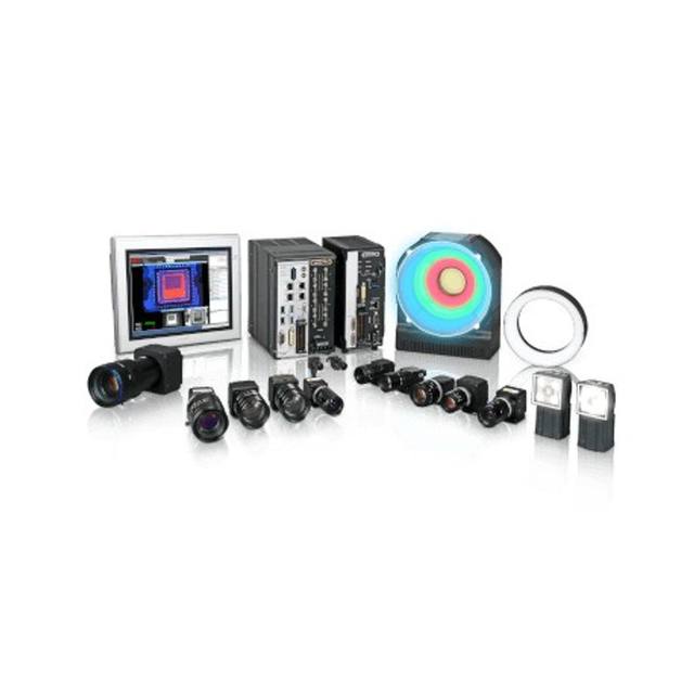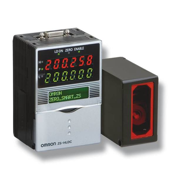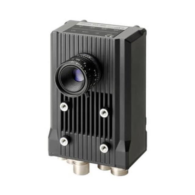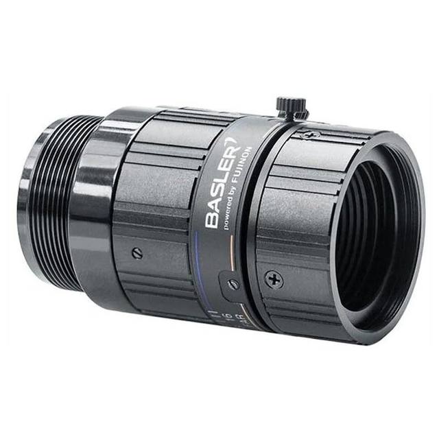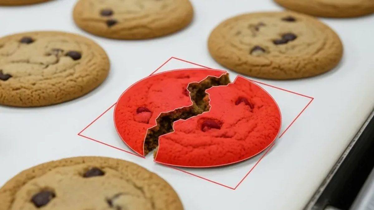
Some defects can be written down as rules. A hole must be present, an edge must be straight, a label must sit within a tolerance box. Cosmetic and surface defects are usually not like that. Scratches, dents, blooms, contamination, weave faults, casting porosity, coating flaws and a hundred other 'you know it when you see it' problems vary in shape, size, position and contrast from one part to the next. Writing a rule that catches every variant without flooding the line with false rejects is, in practice, close to impossible.
This is the gap that deep-learning visual inspection fills. Instead of describing the defect, you show the system examples of good and bad parts and let it learn the boundary. That changes the economics of difficult inspection tasks, but it does not change the laws of imaging: an AI model can only classify what the optics and lighting actually rendered into the image. The hardware on this page exists to put the defect on the sensor with high, repeatable contrast so the model has something to learn from.
This guide frames the inspection problem, explains where AI is the right tool (and where it is not), and walks through the camera, lighting and lens decisions that decide whether your defect detection works on the line or only in the demo.
When AI is the right tool — and when it is not
Deep-learning inspection earns its place when the defect is hard to describe with explicit rules: variable appearance, low contrast against a busy or textured background, many acceptable part variants, or a defect catalogue that keeps growing as production reveals new failure modes. In these cases a learned model generalises from examples far better than a hand-tuned threshold pipeline, and it can be retrained as new defect types appear rather than rebuilt from scratch.
It is the wrong tool when a deterministic measurement will do the job more cheaply and with full traceability. Reading a code, gauging a dimension to a tolerance, checking presence or absence, or confirming a fixed pattern is usually better served by classical machine vision or a smart-camera tool, which give a precise, auditable pass/fail without a training set. A good system often combines both: rule-based logic for the measurable checks and a deep-learning stage for the cosmetic defects that defy rules.
The honest test is whether you can write down, unambiguously, what makes a part bad. If you can, start with classical vision. If every attempt produces either escapes or false rejects, the problem is a defect-class problem and AI is the appropriate approach. Either way, the imaging chain in front of it has to be solid first.
- Good fit for AI: scratches, dents, stains, contamination, texture and weave faults, porosity, coating and finish defects, variable natural products.
- Better with classical vision: code reading, dimensional gauging, presence/absence, fixed-pattern verification, anything you can specify as a tolerance.
- Common reality: a hybrid pipeline — rules for the measurable, deep learning for the cosmetic.
Why the imaging makes or breaks the model
The single biggest cause of disappointing AI inspection is not the model — it is the image. If a defect is barely visible to a trained operator under the chosen lighting, it will be barely visible to the network, and no amount of training data will reliably recover it. The objective of the optical setup is to maximise the contrast between defect and background while keeping the appearance of good parts stable and repeatable, frame after frame, shift after shift.
Repeatability matters as much as raw contrast. A model trained on images captured under one lighting and exposure regime degrades quickly if the production images drift — ambient light leaking in, lamps ageing, exposure auto-adjusting, parts presented at varying angles. Locking down the geometry (fixed working distance, fixed part presentation), shrouding ambient light, using stable controlled illumination and fixing camera gain and exposure are what let a model trained today keep working in six months.
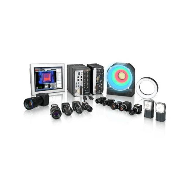
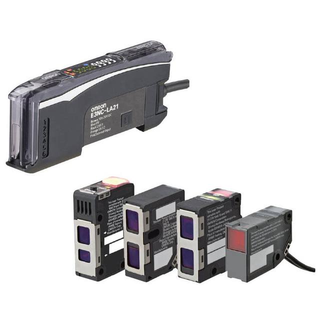
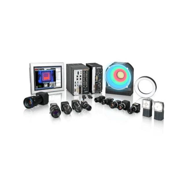
This is why the recommended hardware is a system, not a camera. The area scan camera, the lens and the lighting are chosen together against the specific defect, and the deep-learning software sits on top of an image that was engineered to reveal it. Sending representative sample images for evaluation early is the fastest way to find out whether the defect is separable at all — and what lighting it takes to make it so.
Choosing the area scan camera
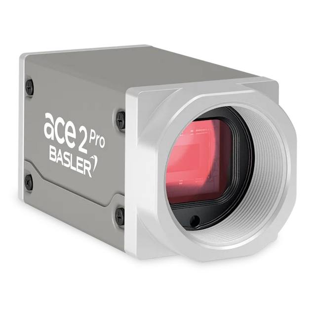
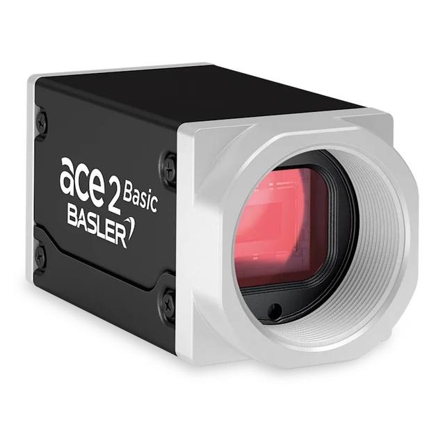
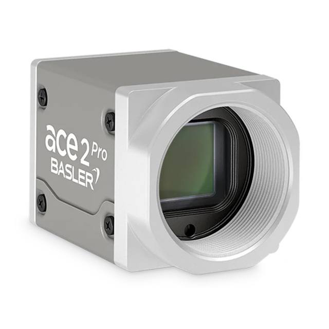
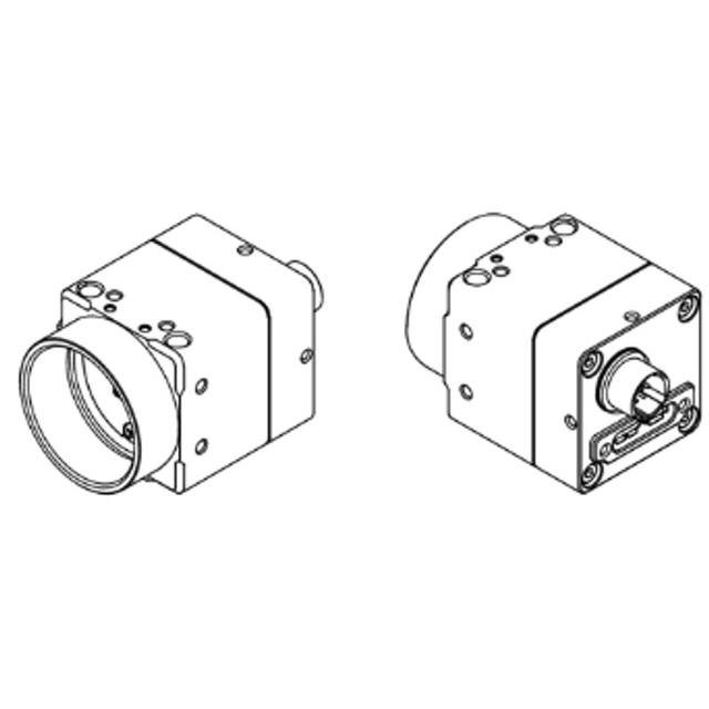
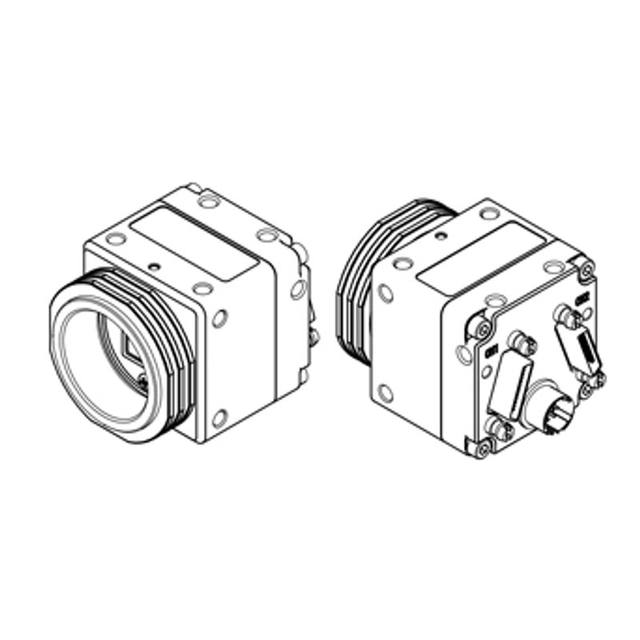
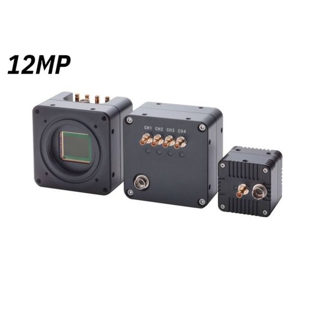
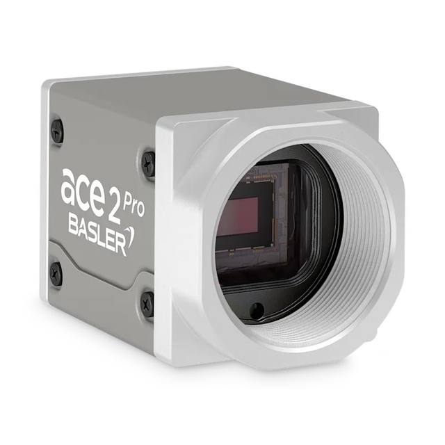
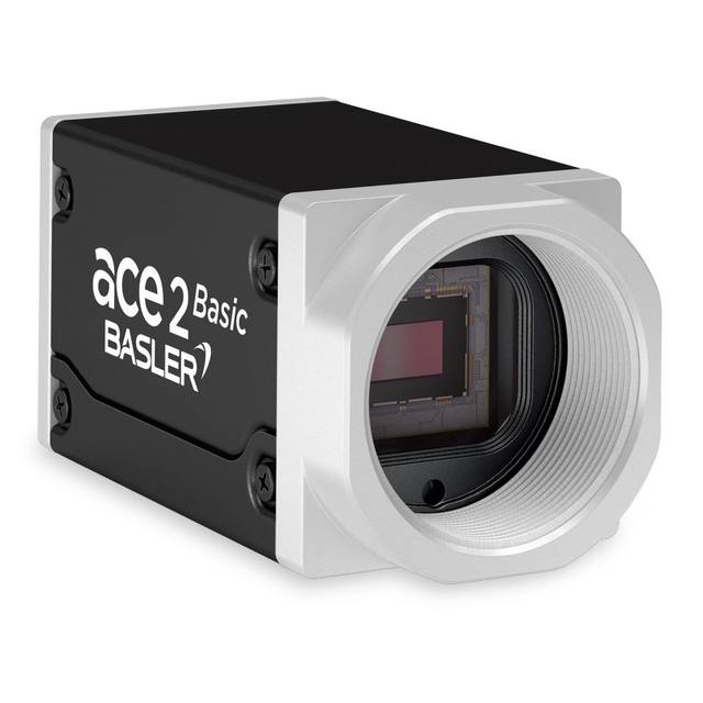
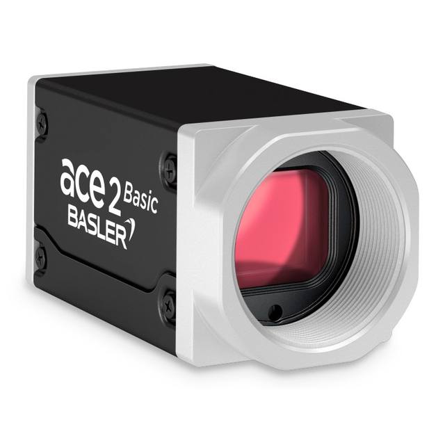
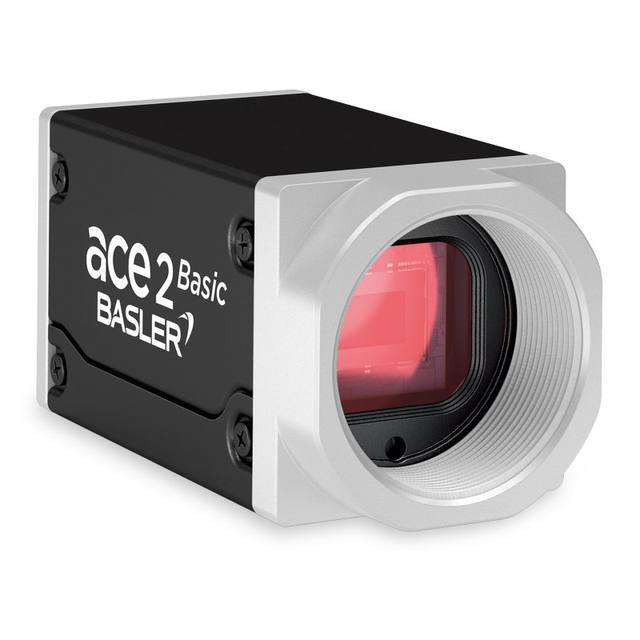
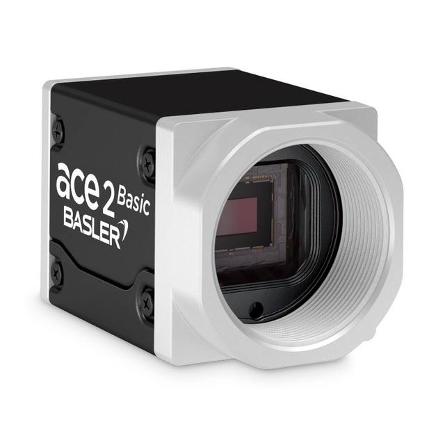
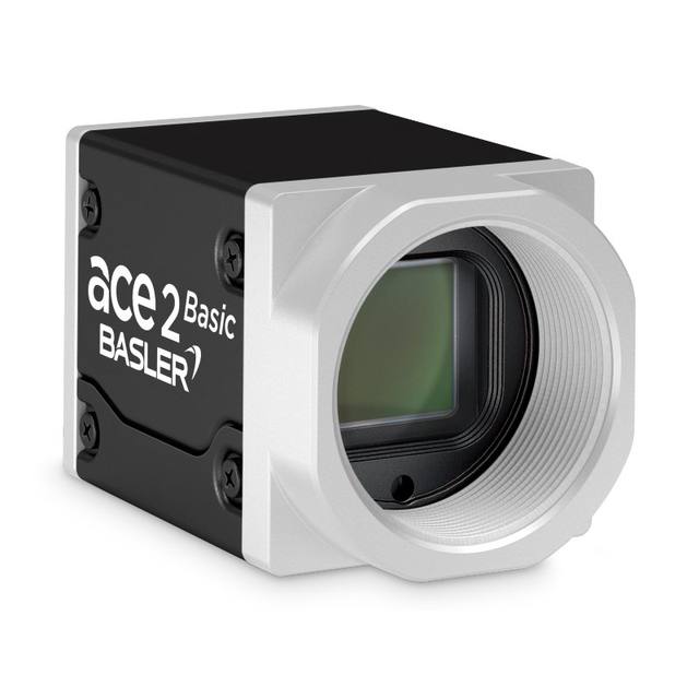
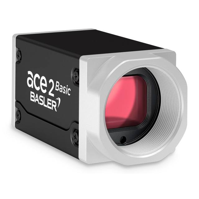
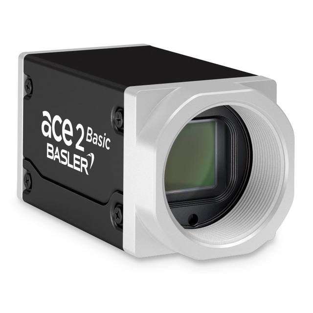
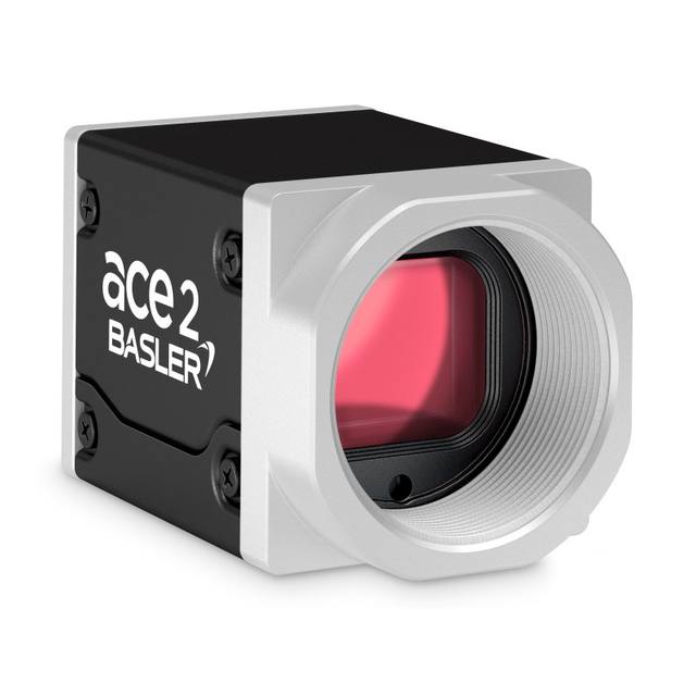
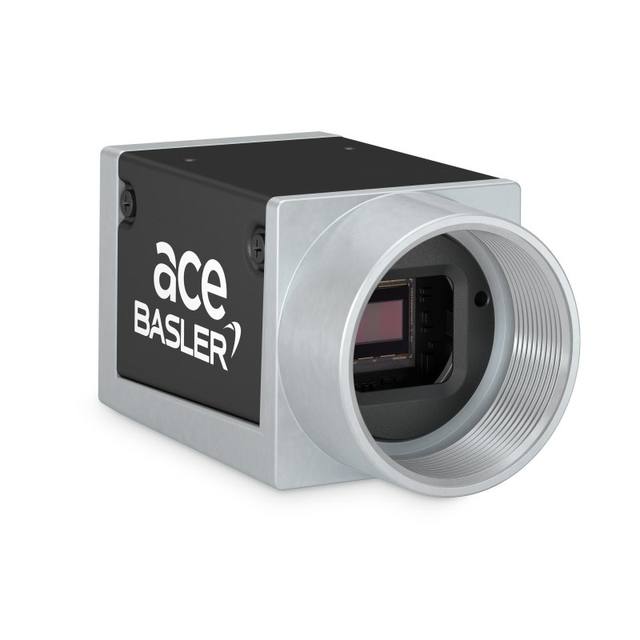
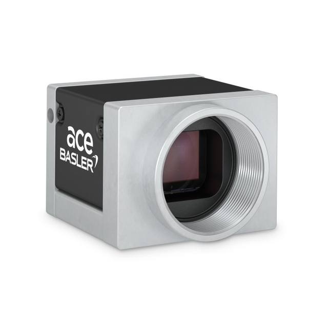
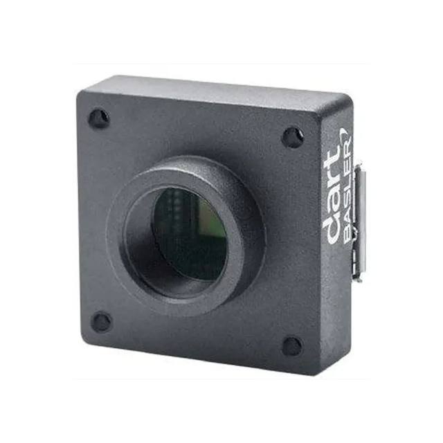
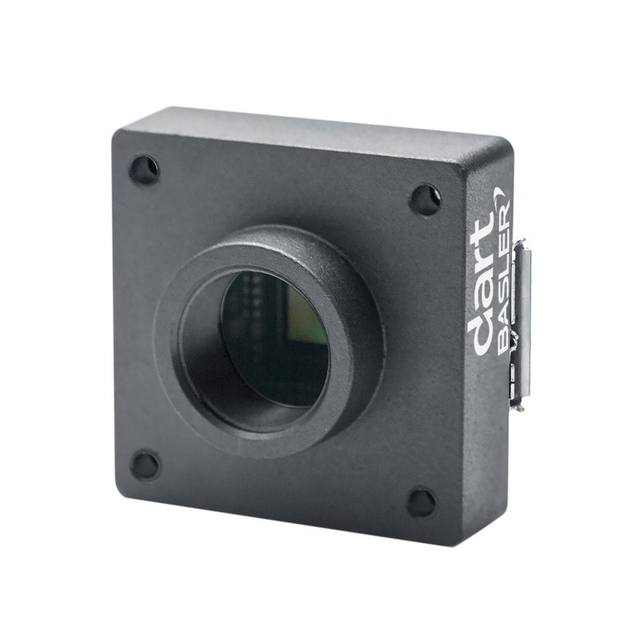
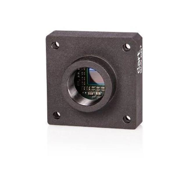
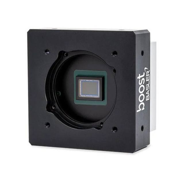
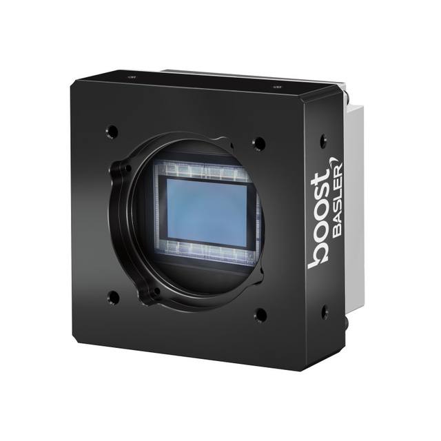
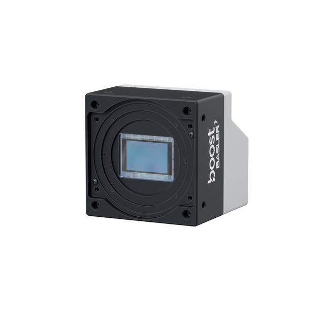
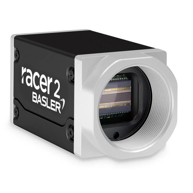
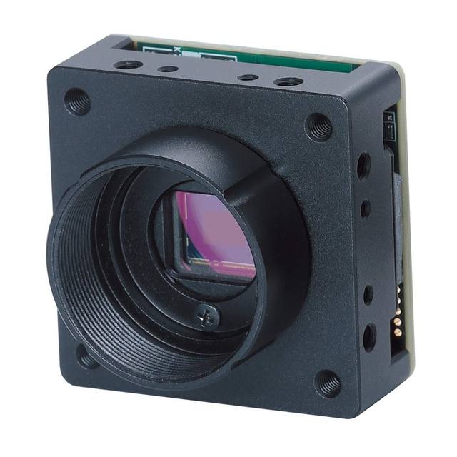
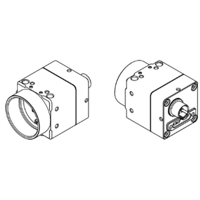
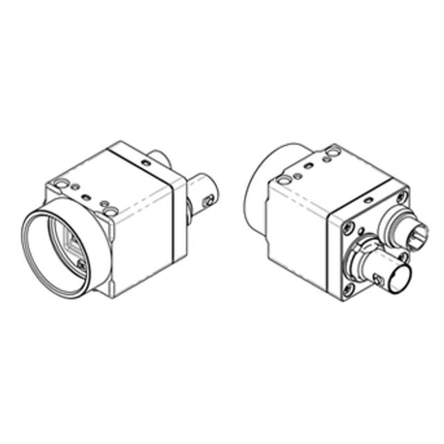
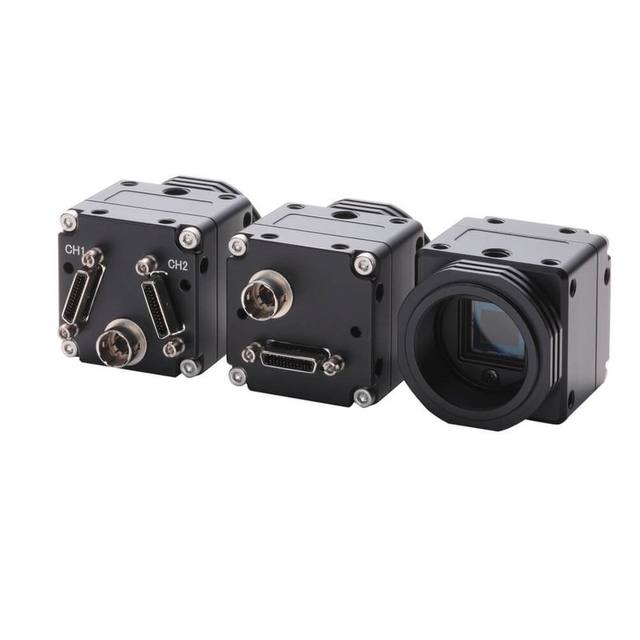
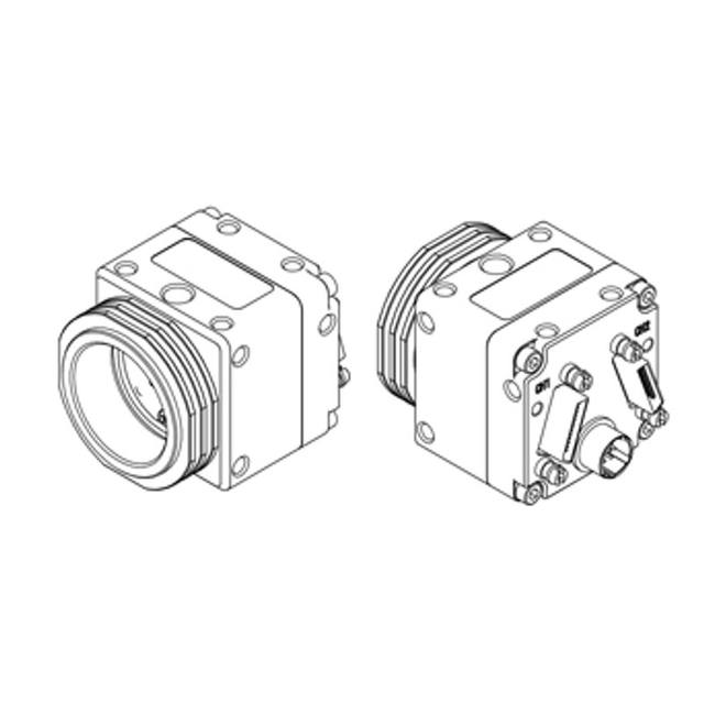
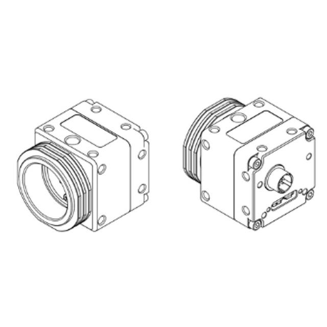
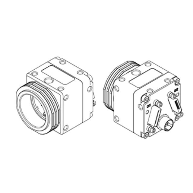
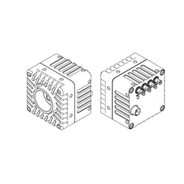
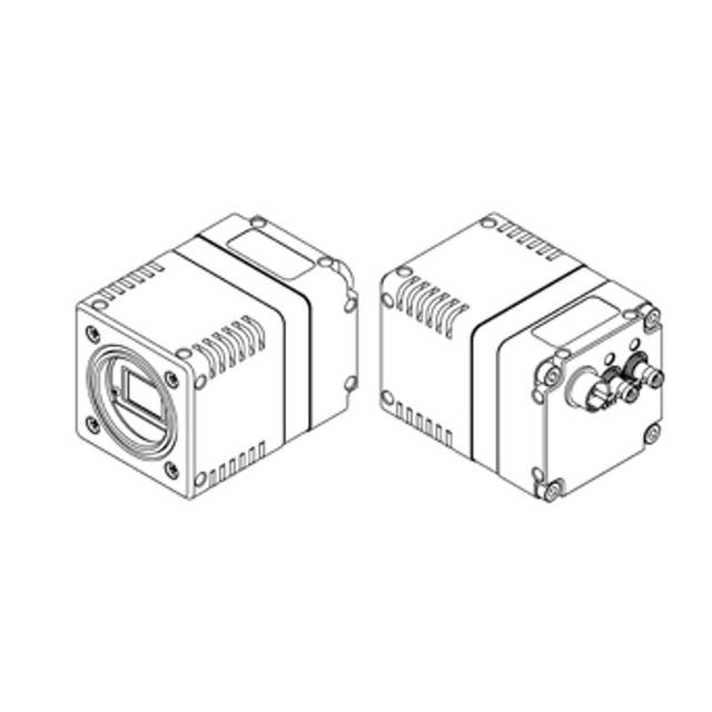
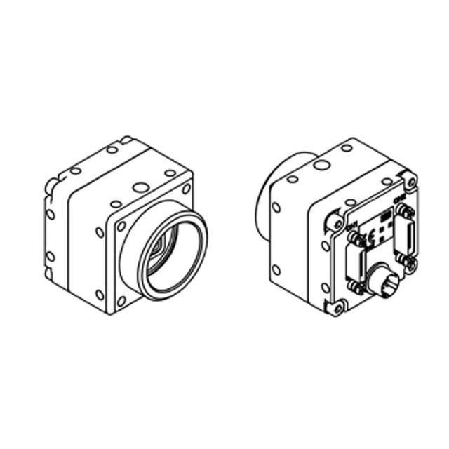
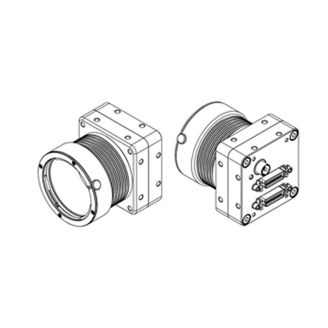
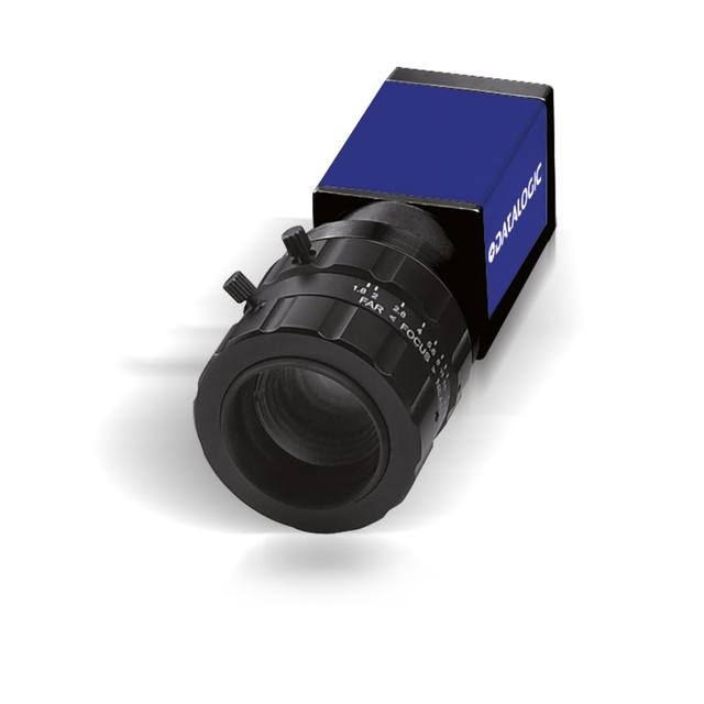
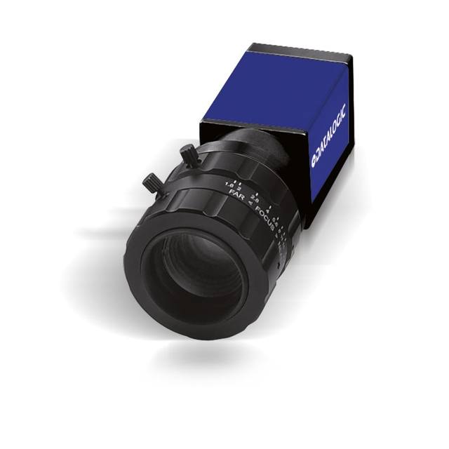
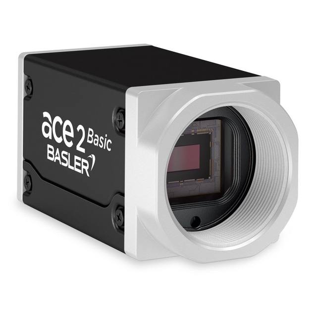
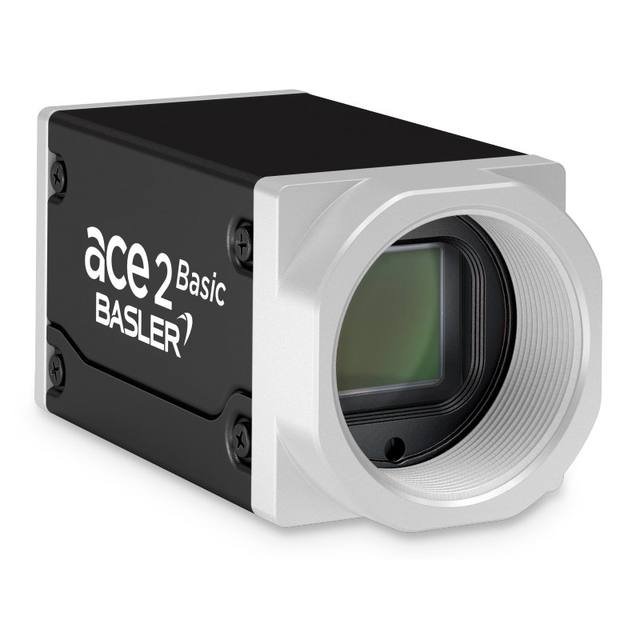
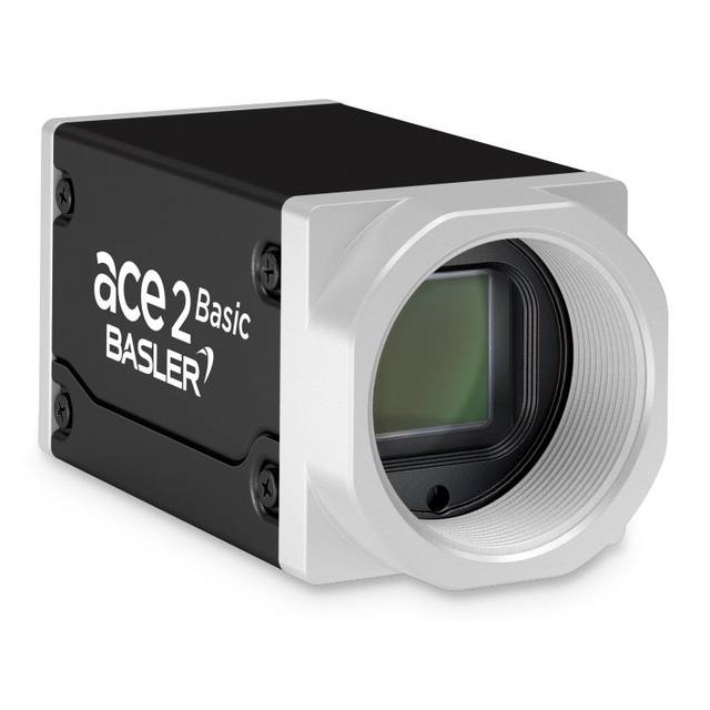
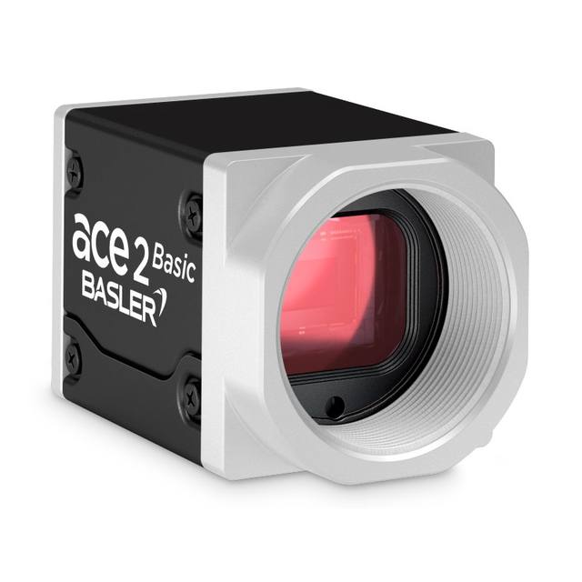
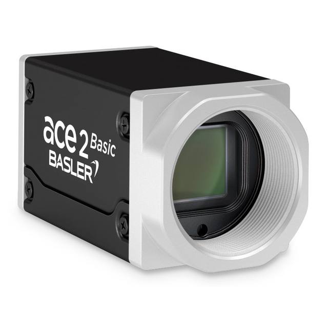
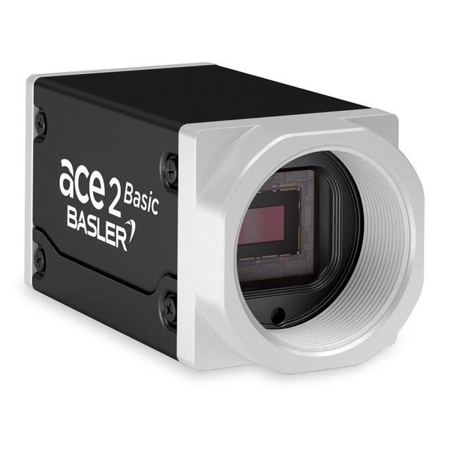
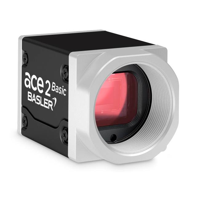
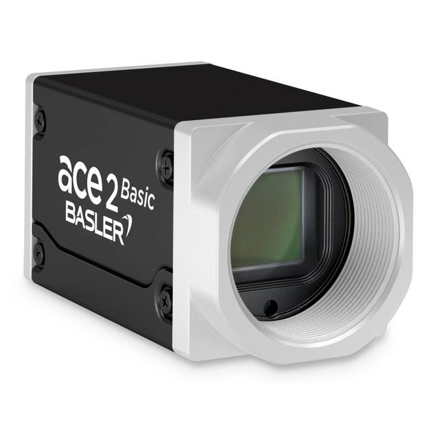
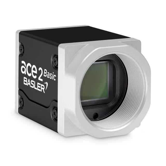
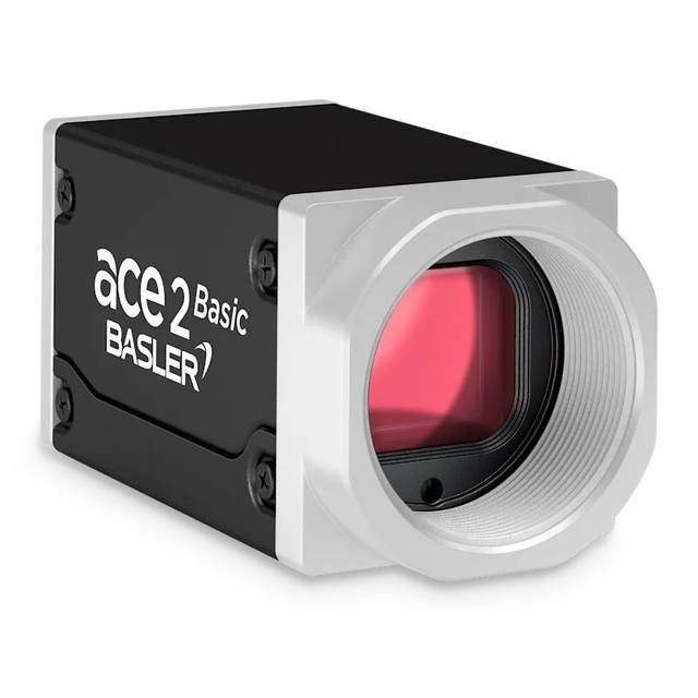
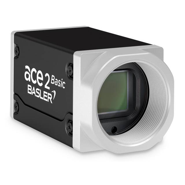
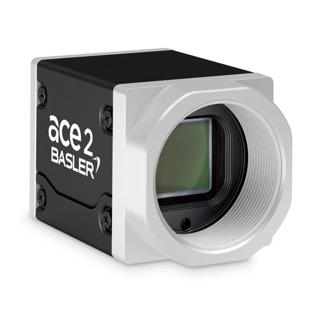
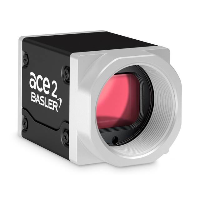
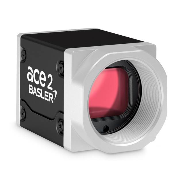
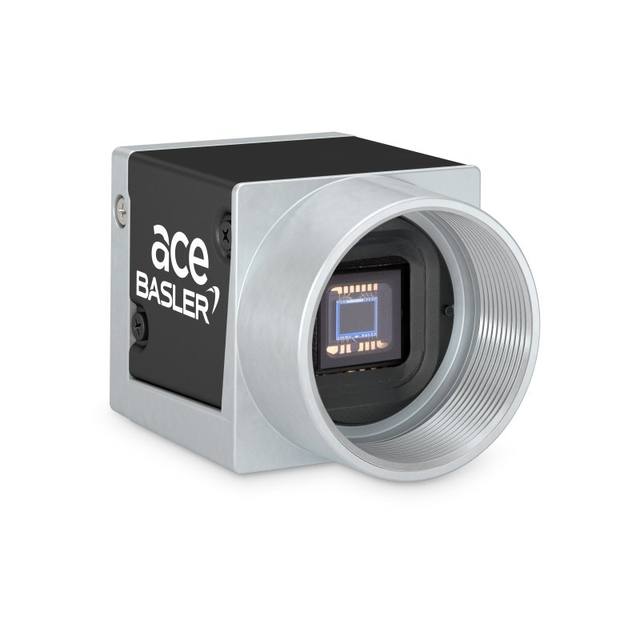
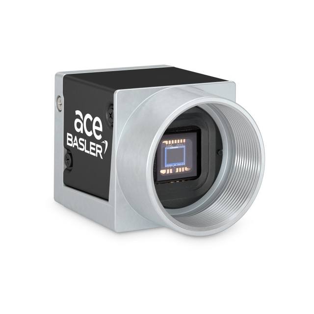
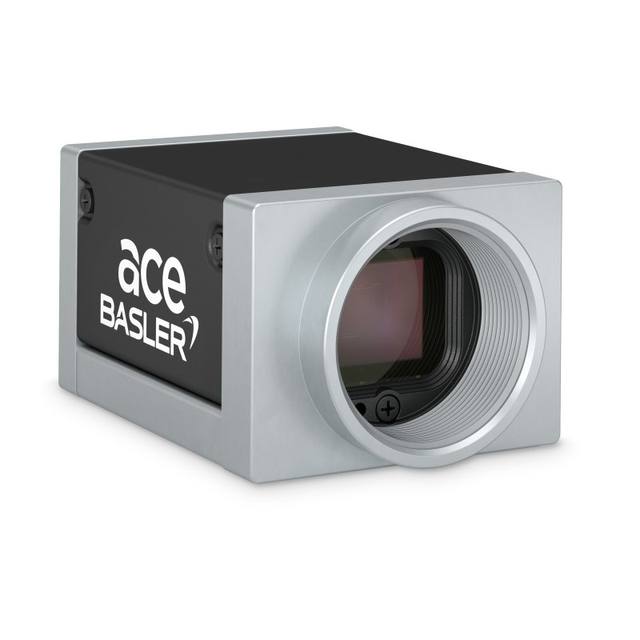
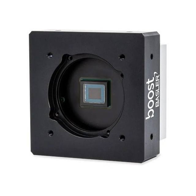
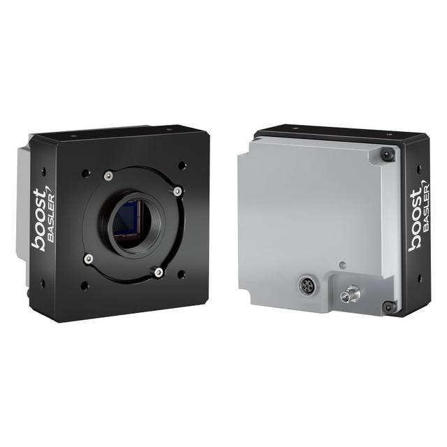
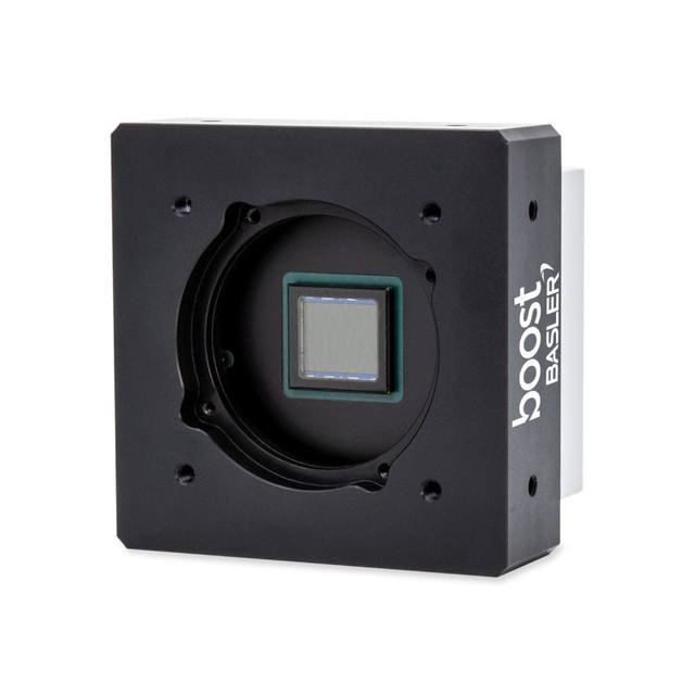
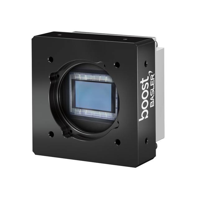
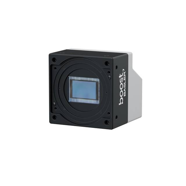
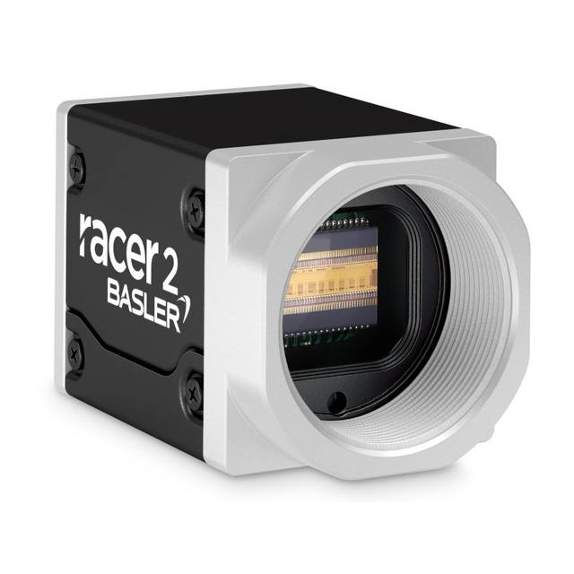
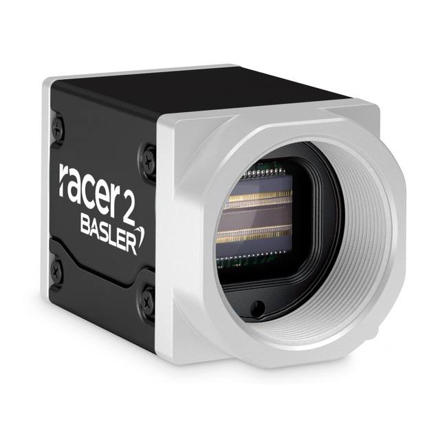
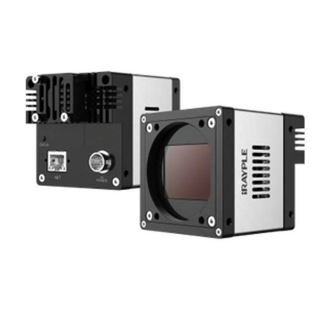
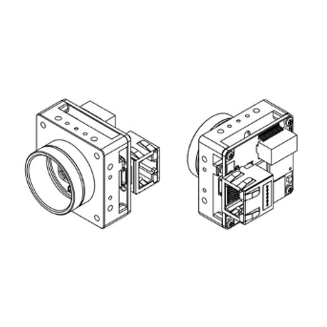
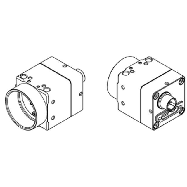
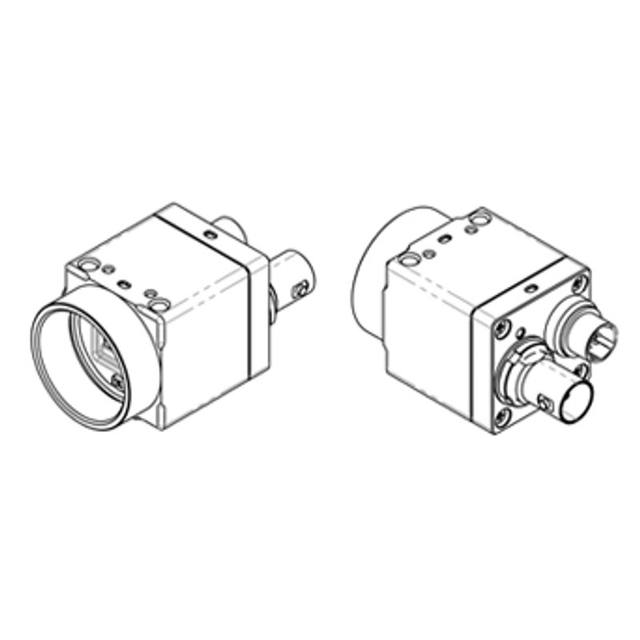
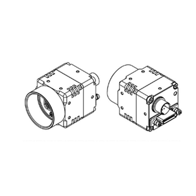
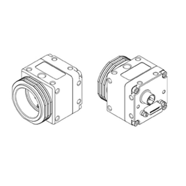
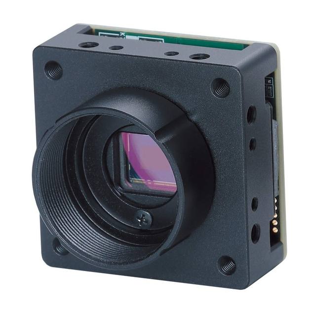
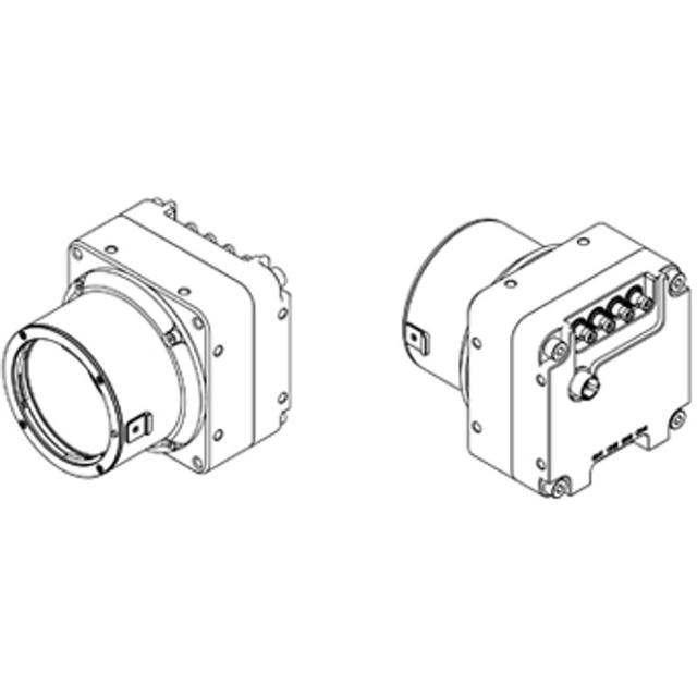
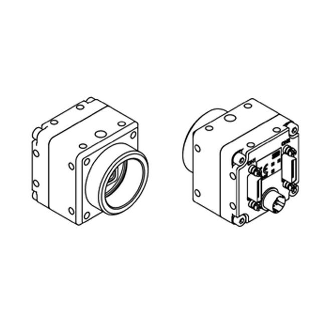
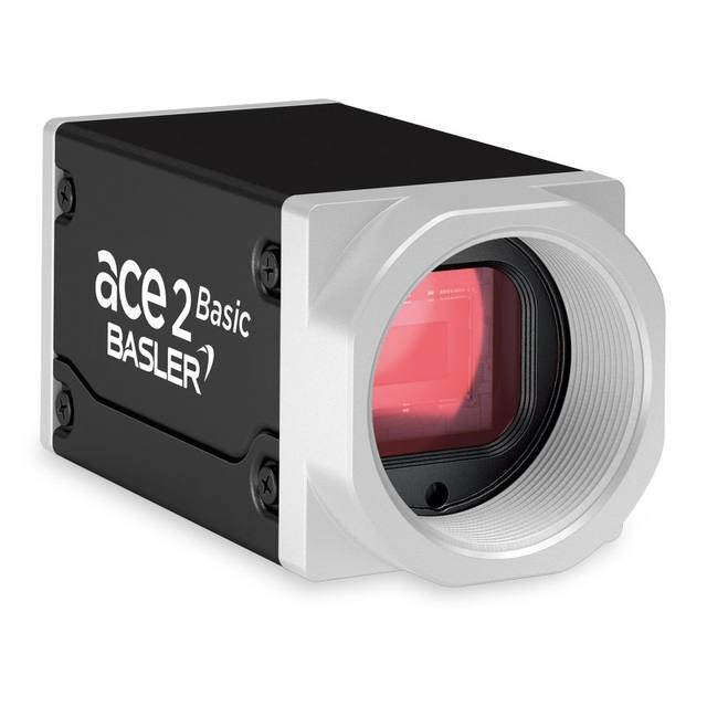
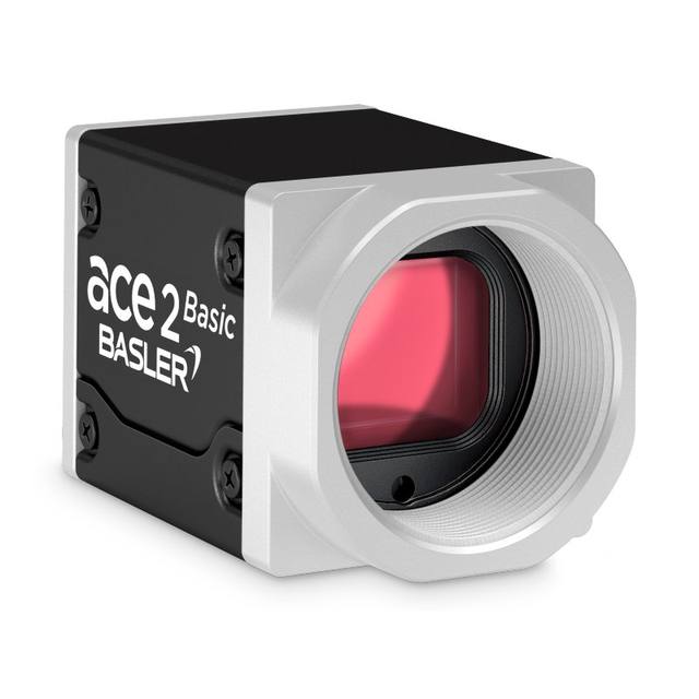
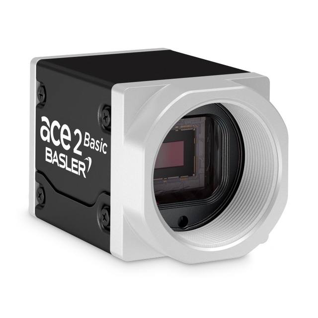
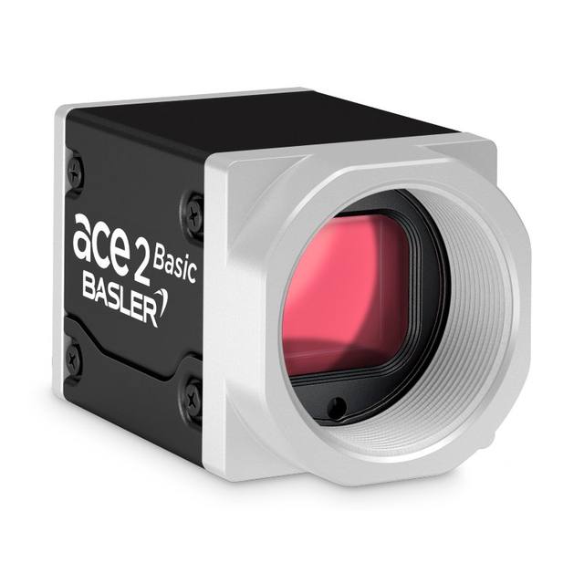
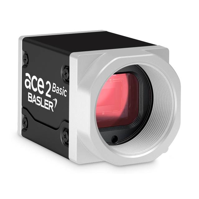
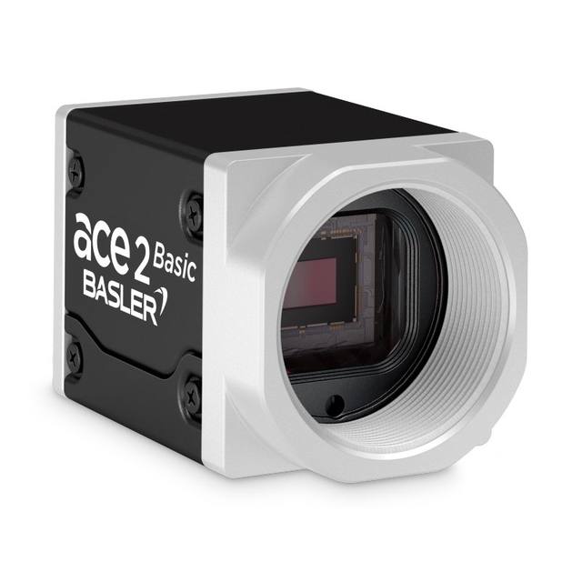
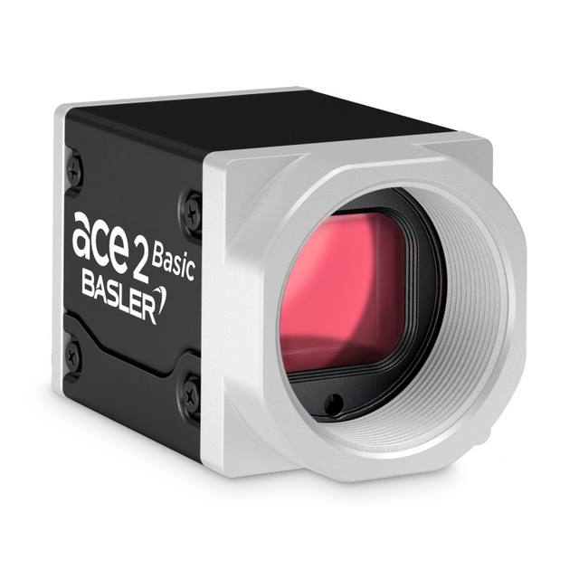
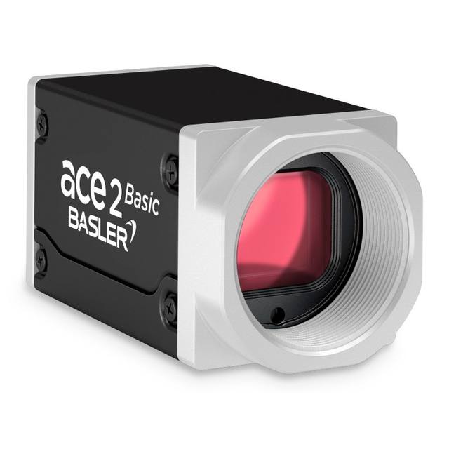
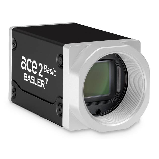
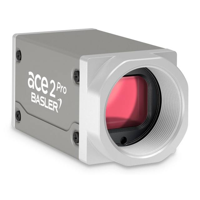
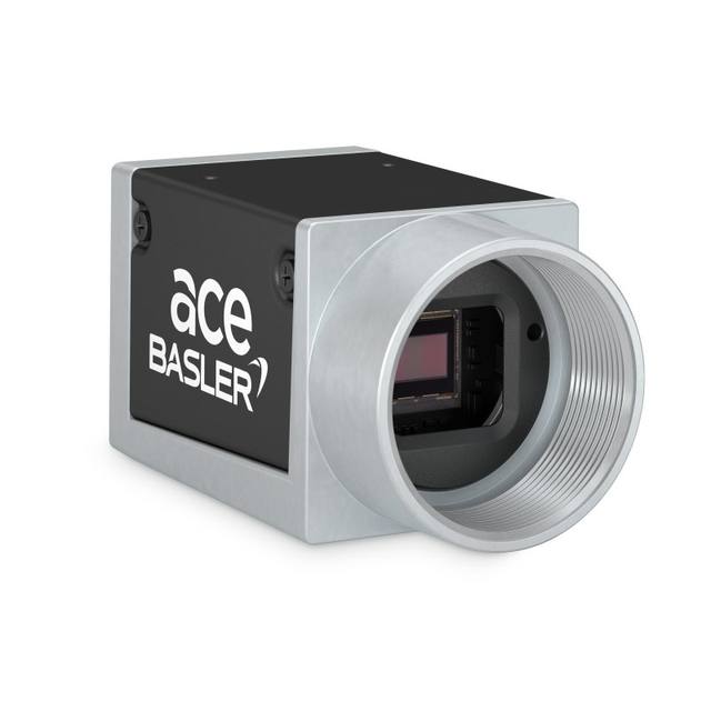
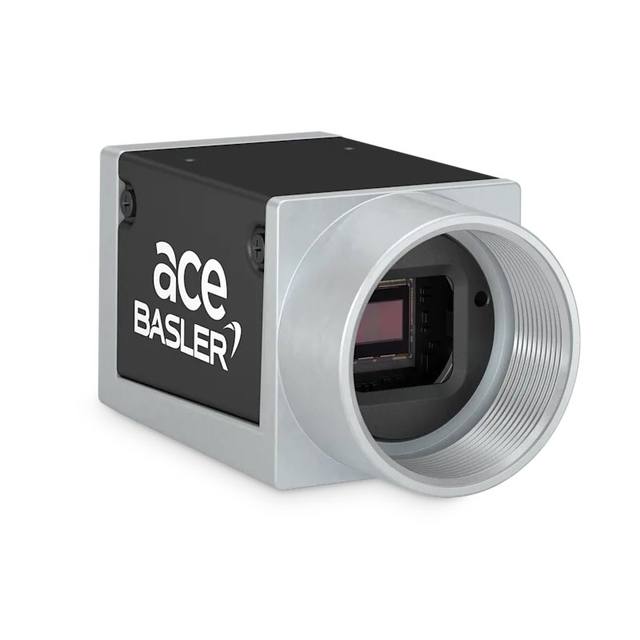
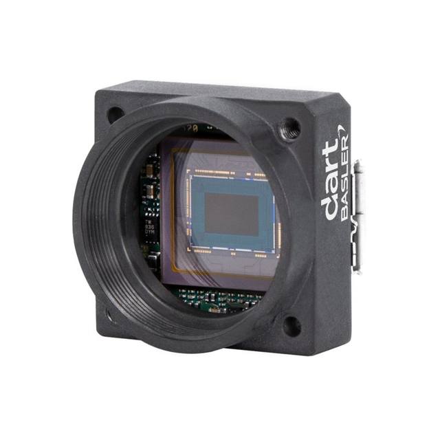
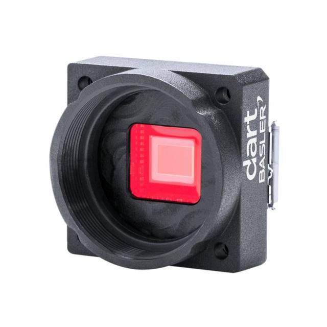
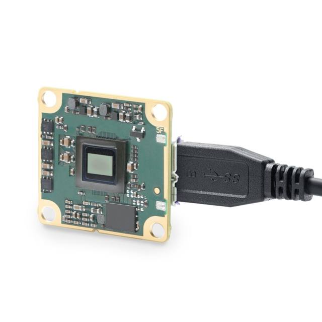
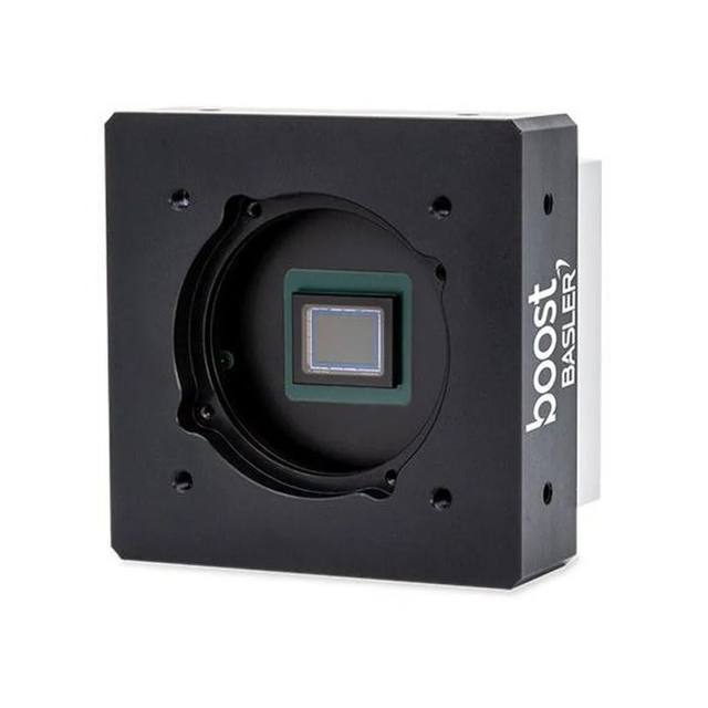
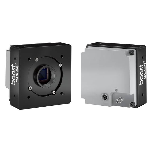
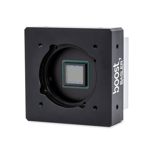
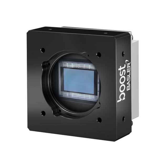
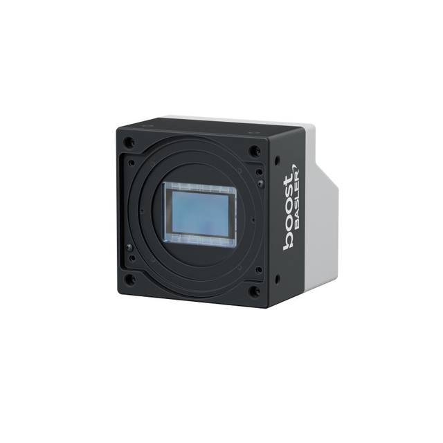
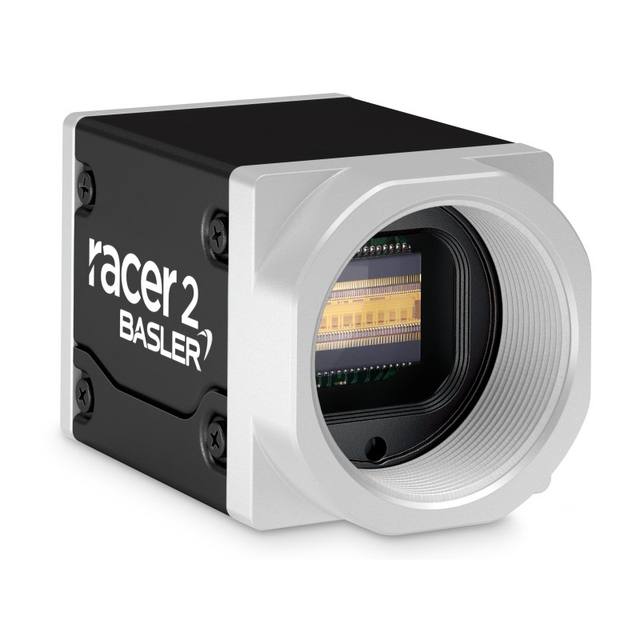
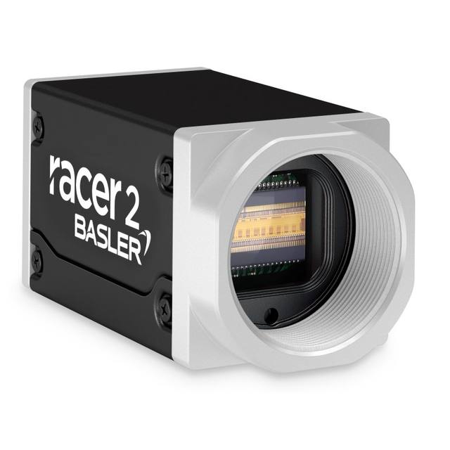
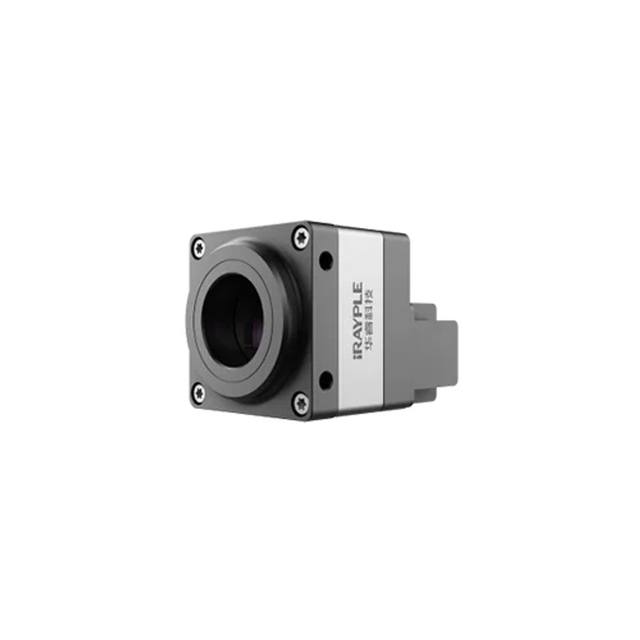
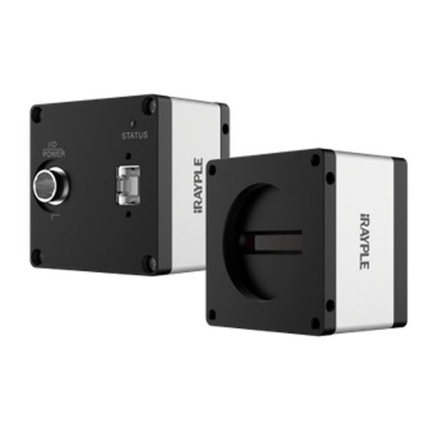
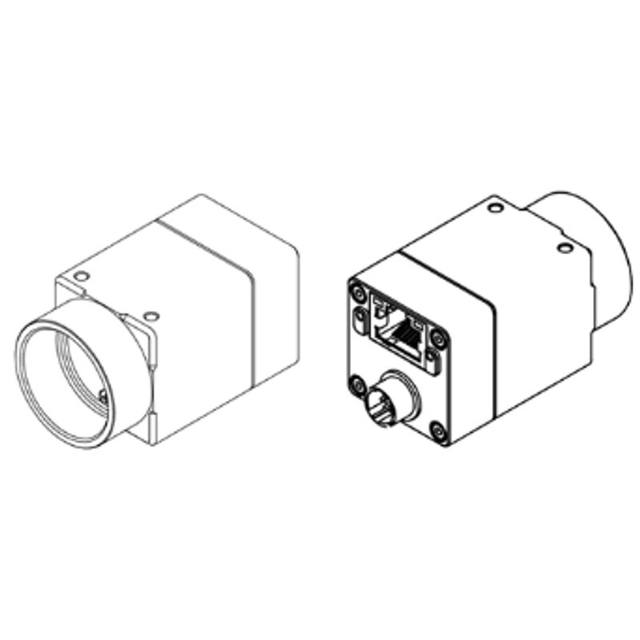
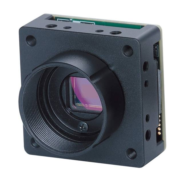
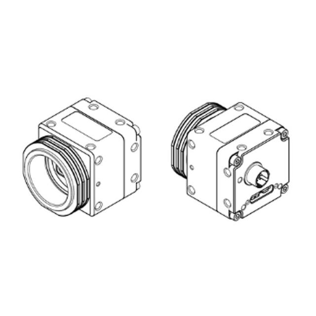
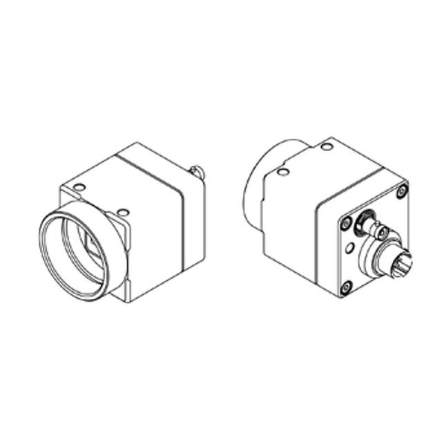
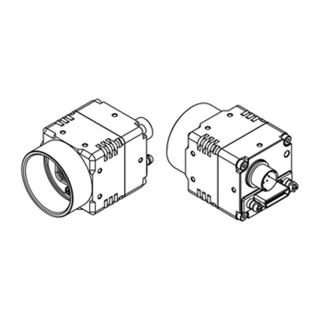
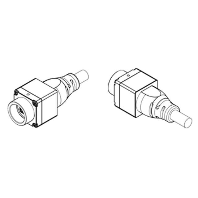
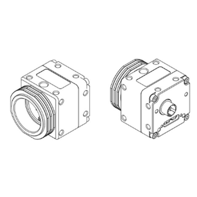
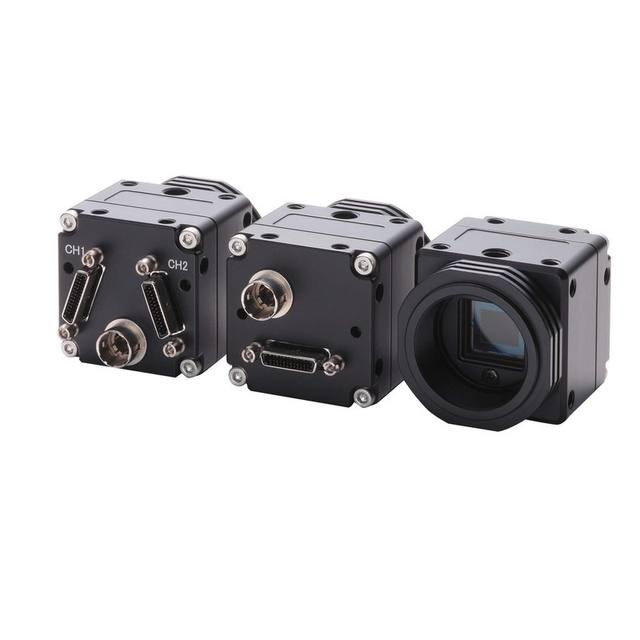
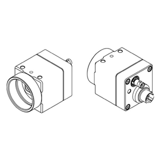
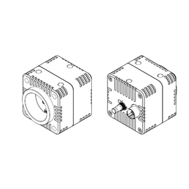
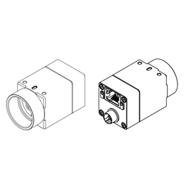
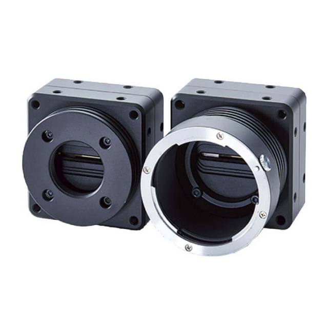
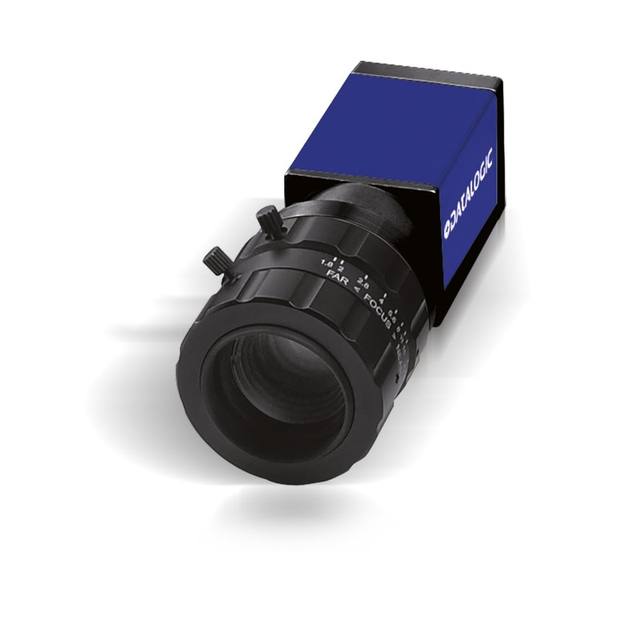
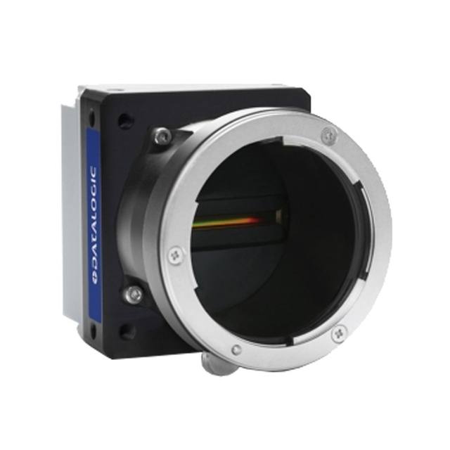
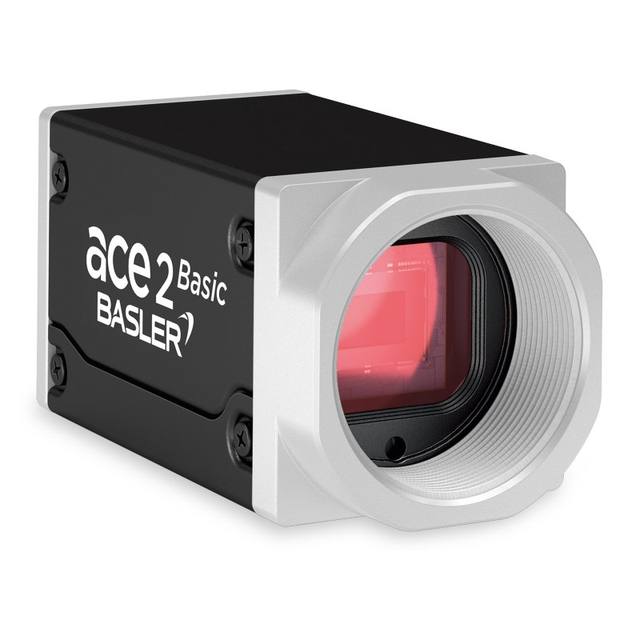
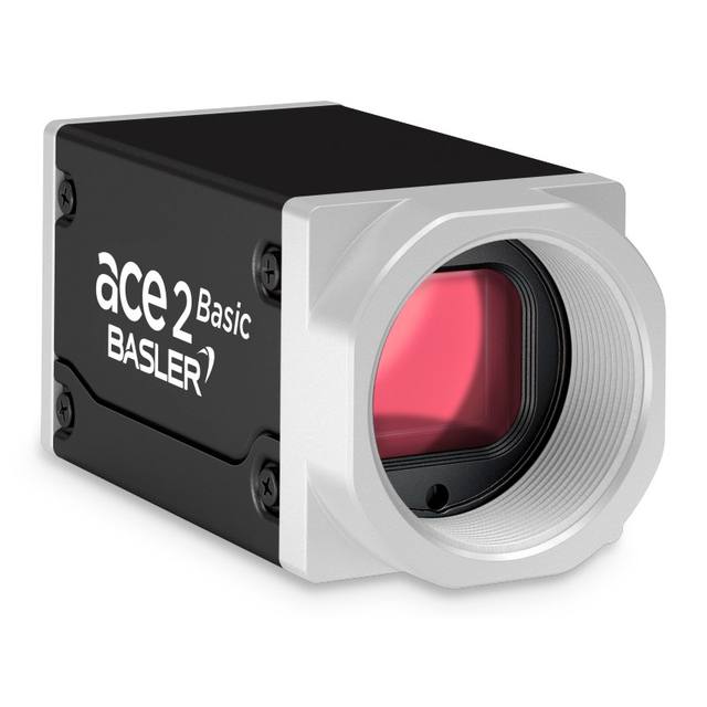
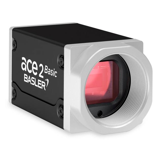
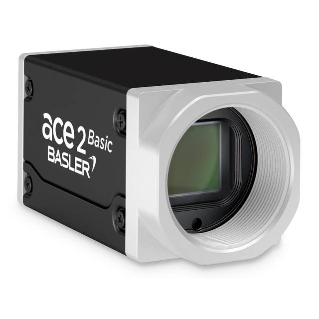
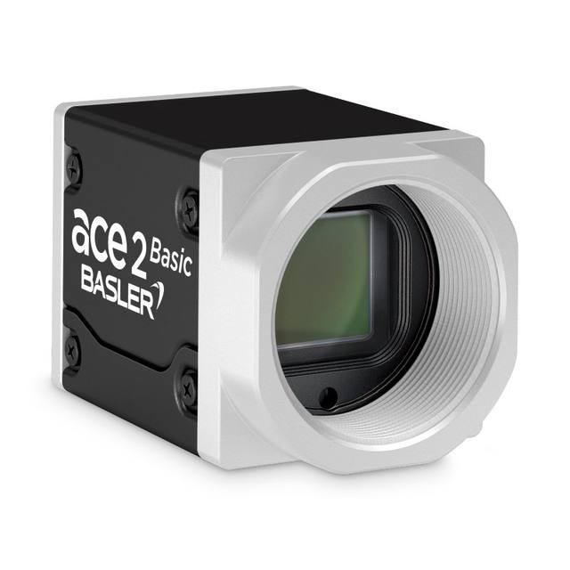
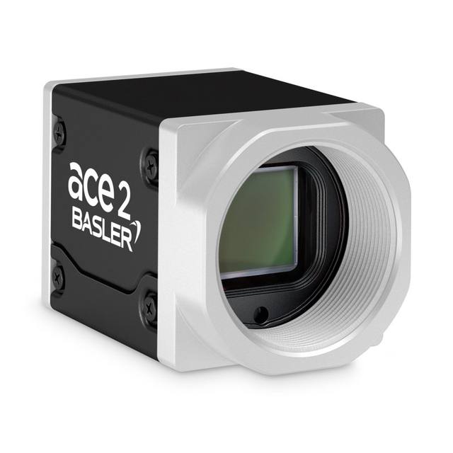
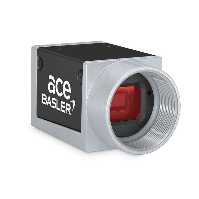
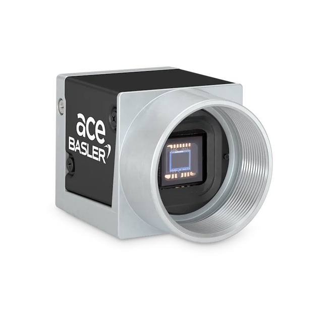
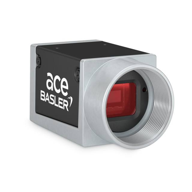
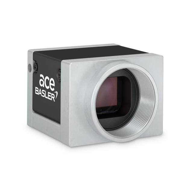
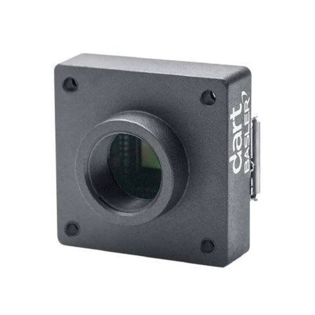
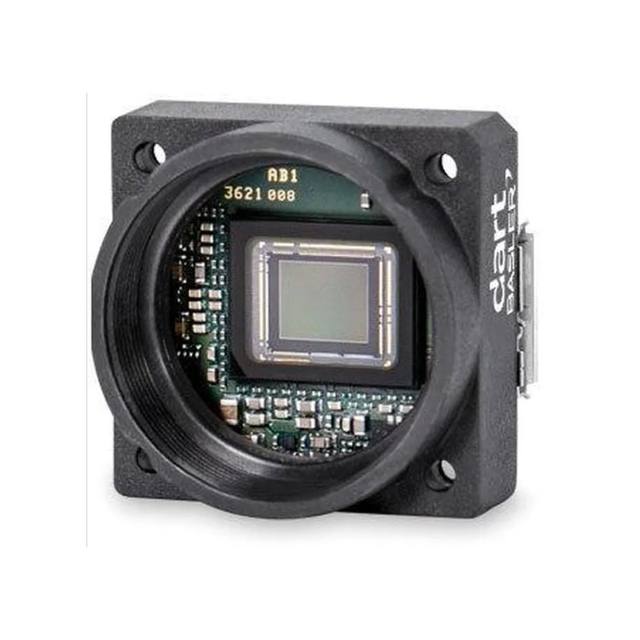
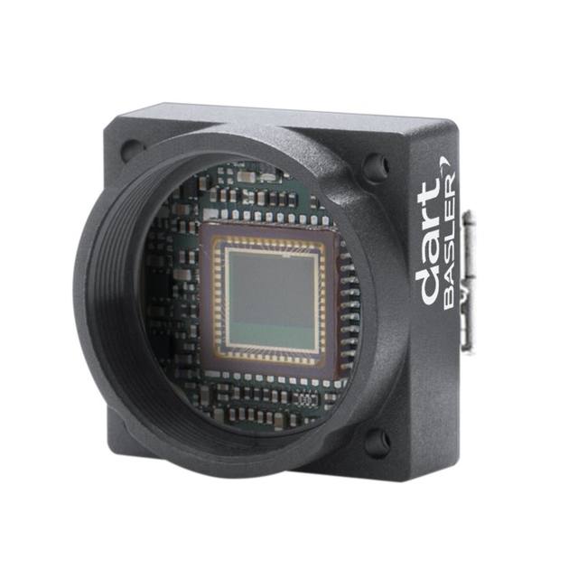
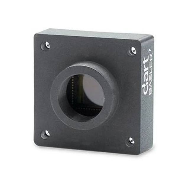
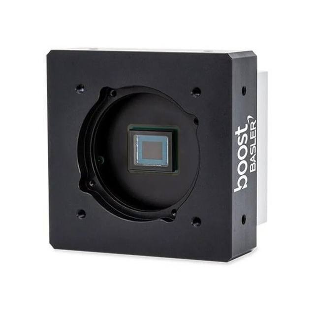
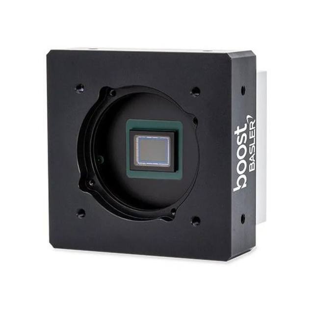
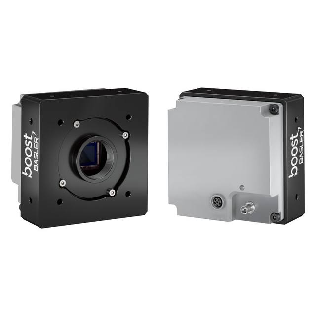
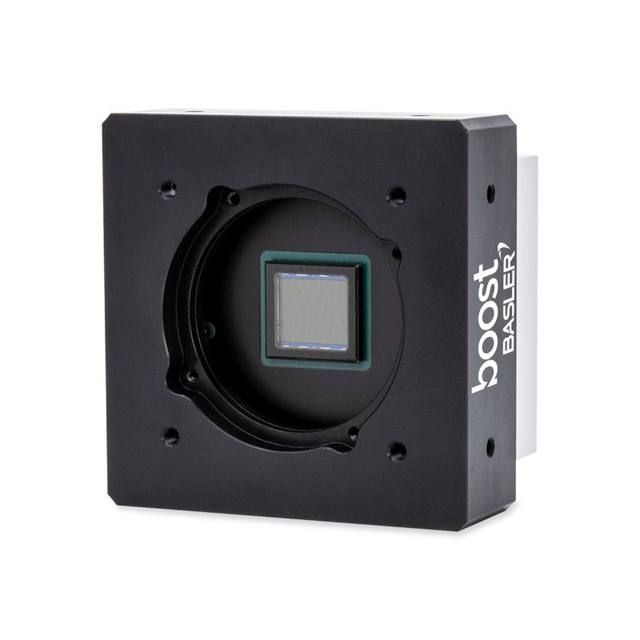
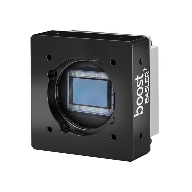
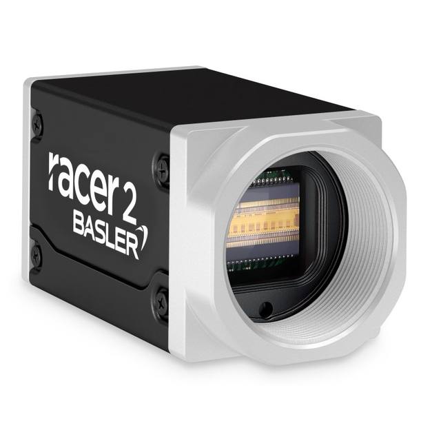
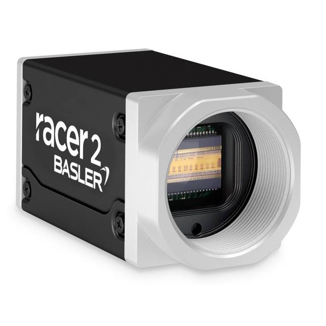
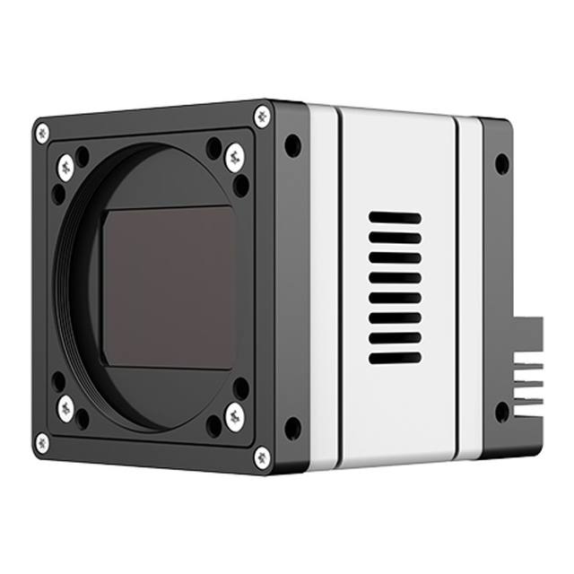
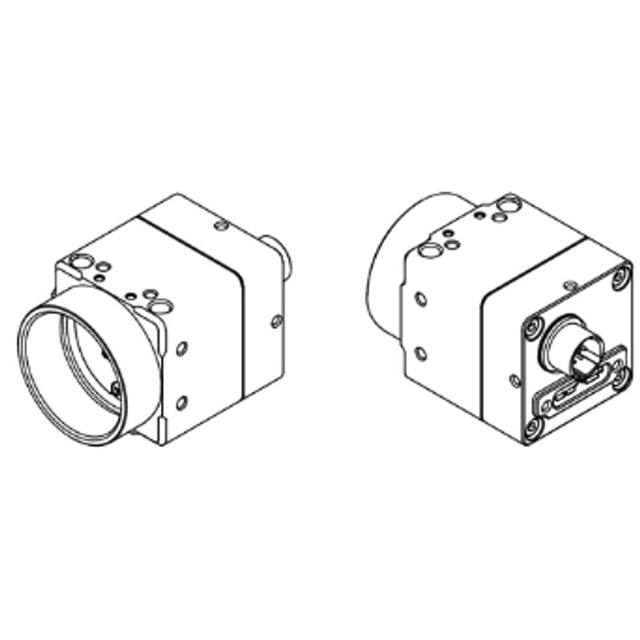
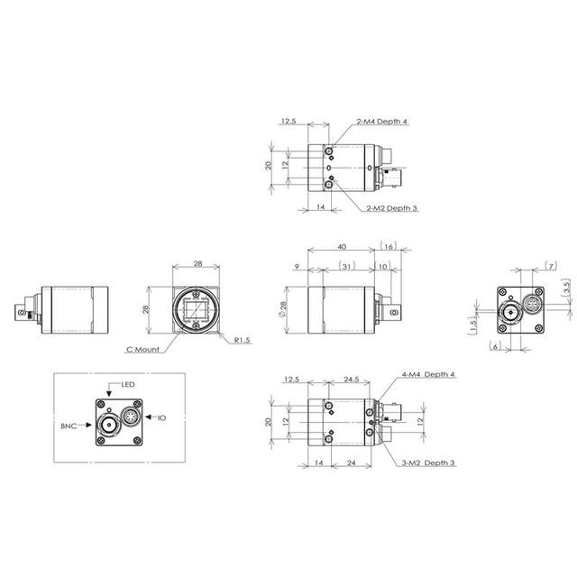
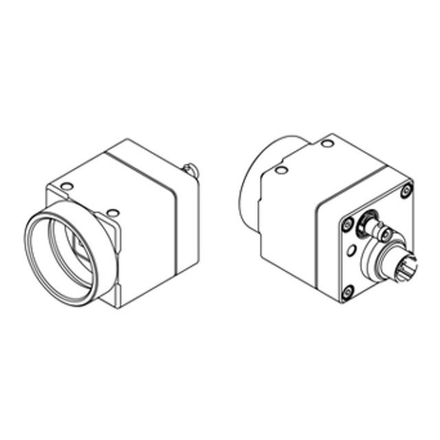
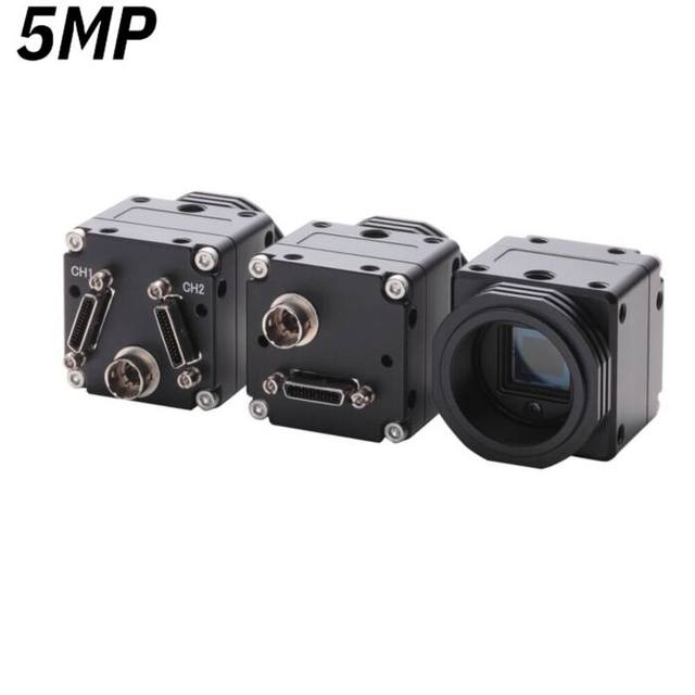
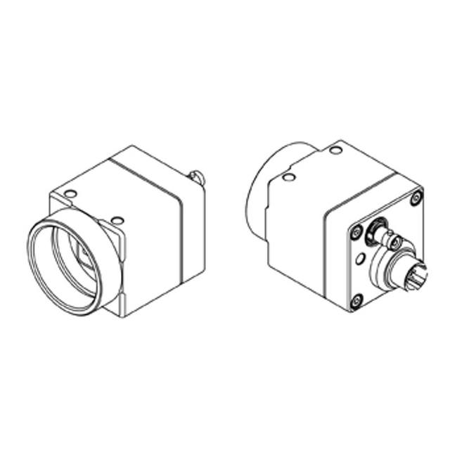
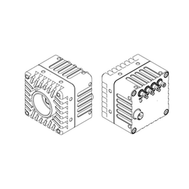
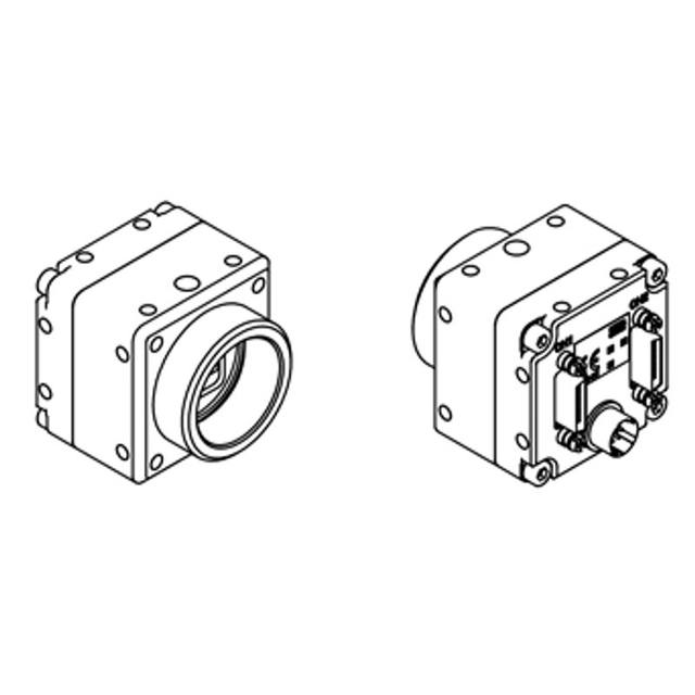
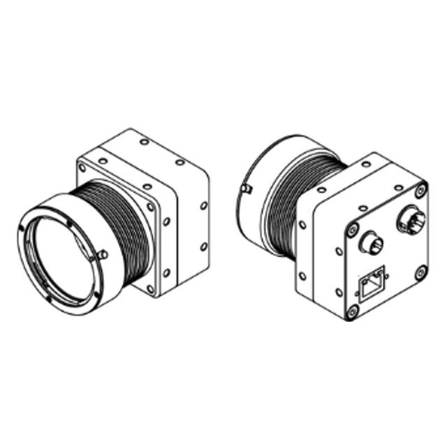
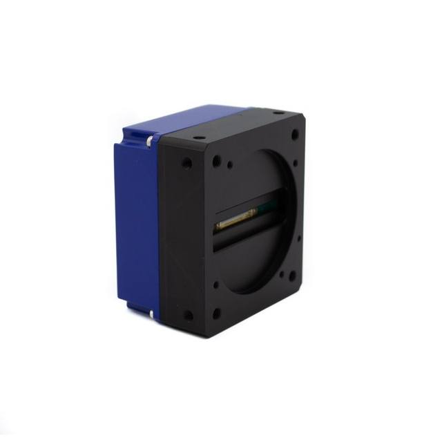
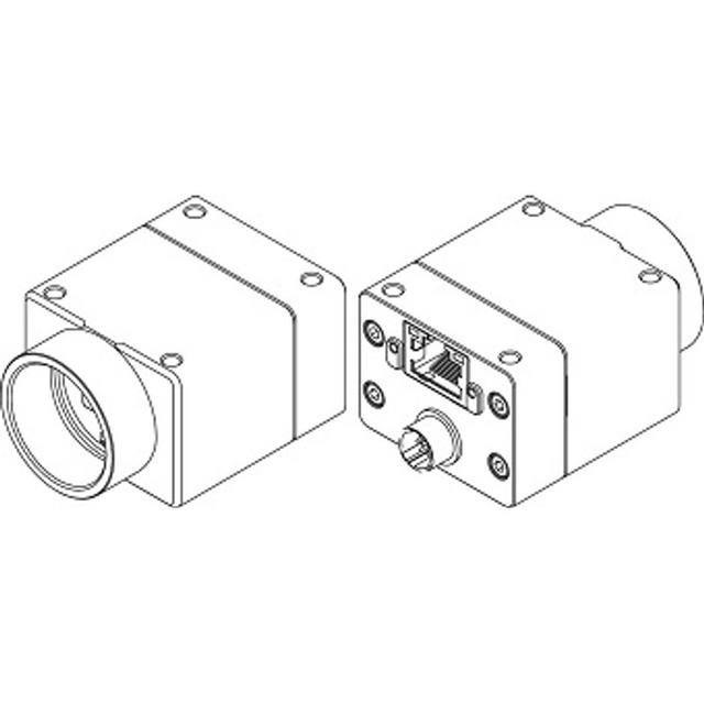
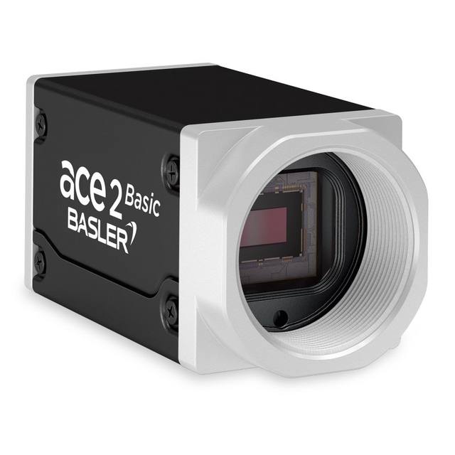
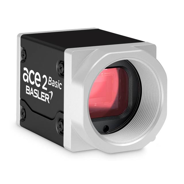
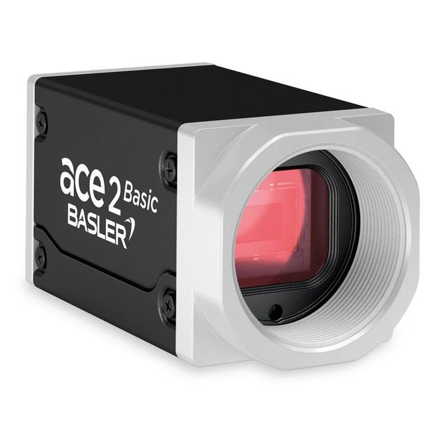
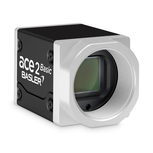
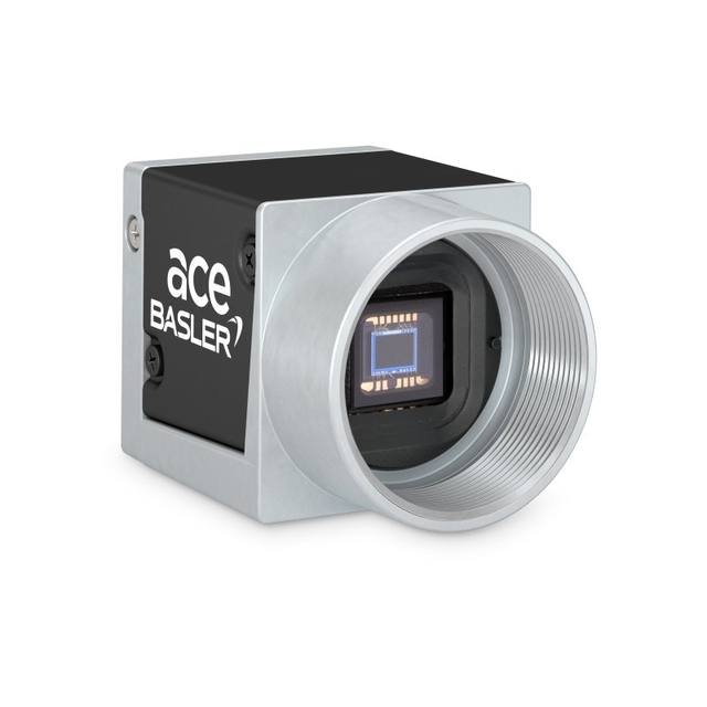
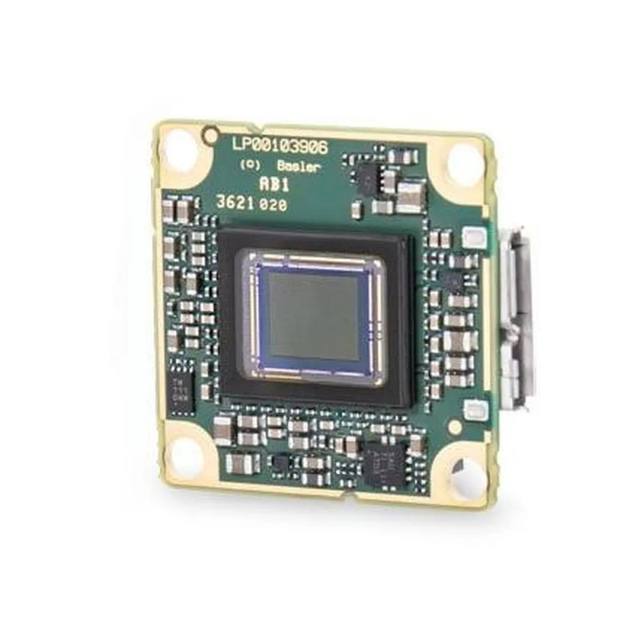
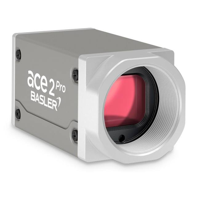
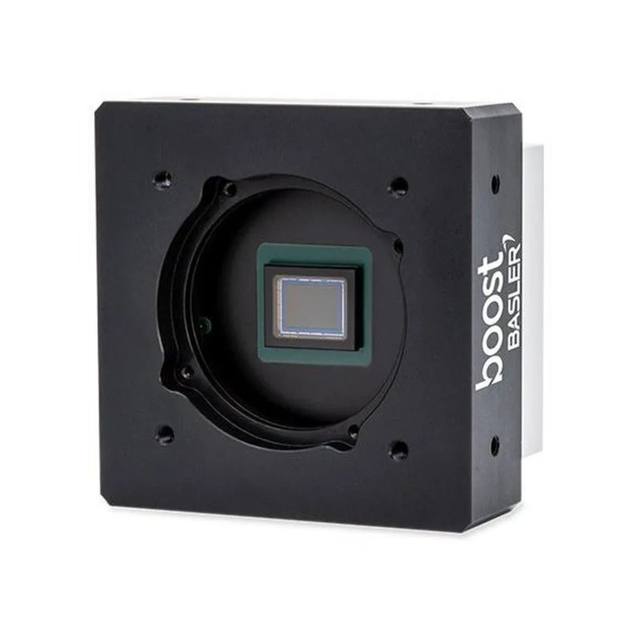
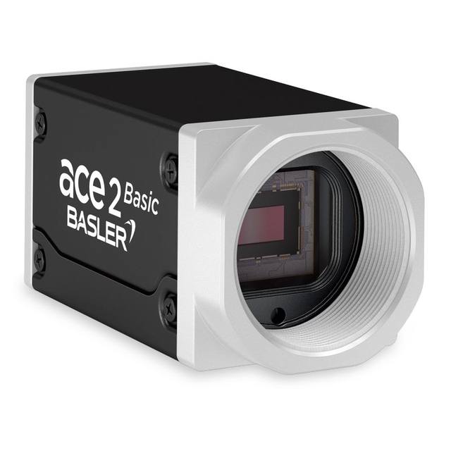
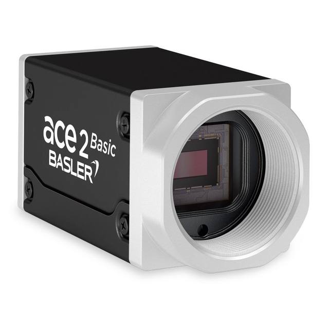
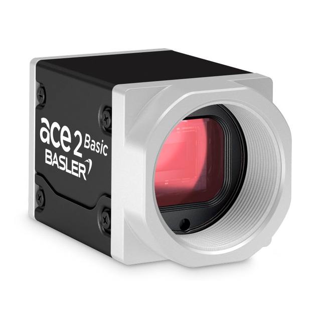
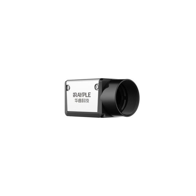
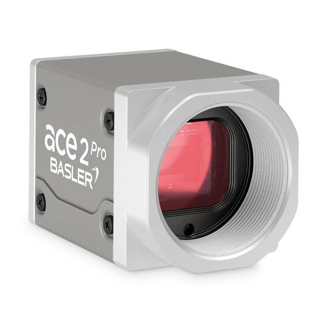
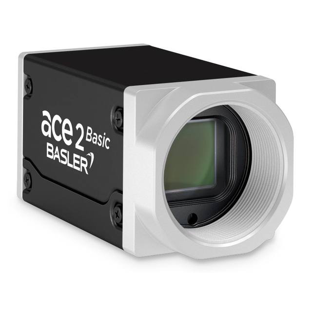
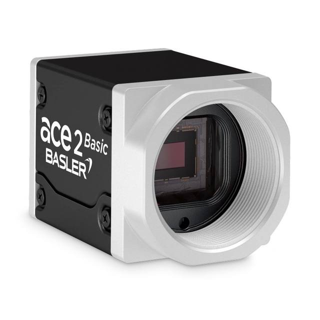
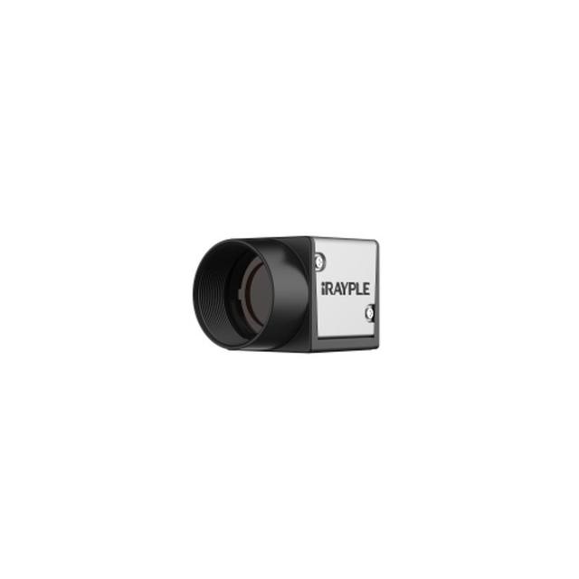
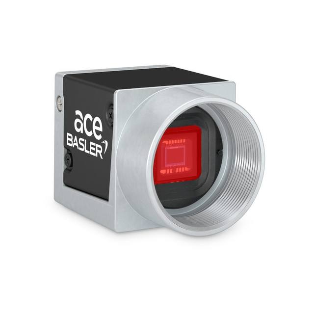
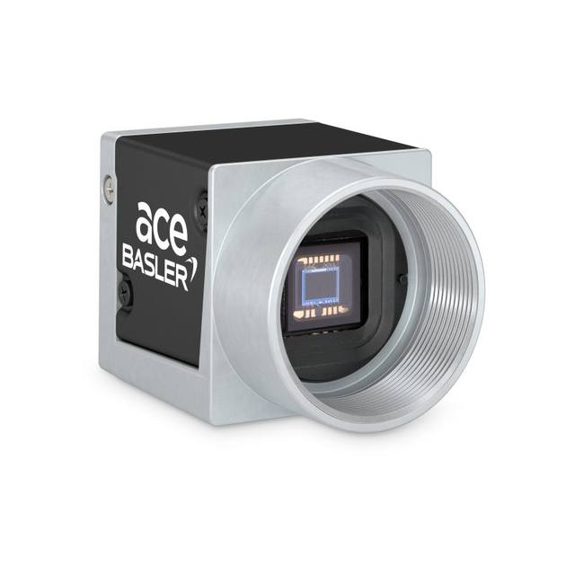
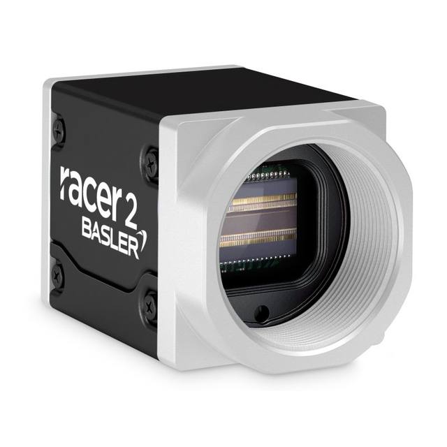
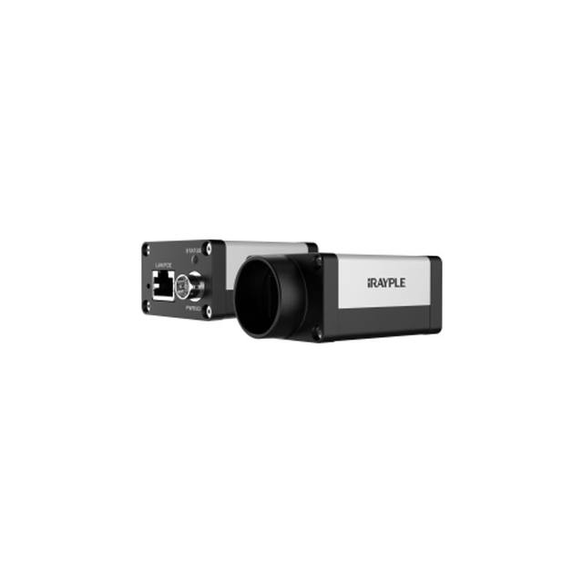
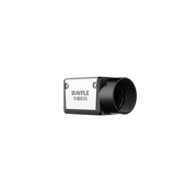
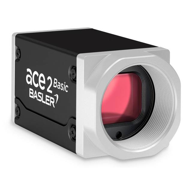
For discrete parts and most cosmetic inspection, an area scan camera is the natural choice: it captures a full 2D frame in a single exposure, which suits parts that index into position and stop, or that can be frozen with a short exposure or a strobe. The starting point is spatial resolution — how many pixels land on the smallest defect you must reliably catch. A useful rule of thumb is to spread the smallest defect across several pixels (roughly three to five), then work back to the sensor resolution given your field of view. Under-resolve the defect and the model has nothing to learn; massively over-resolve it and you pay in data, bandwidth and cost without benefit.
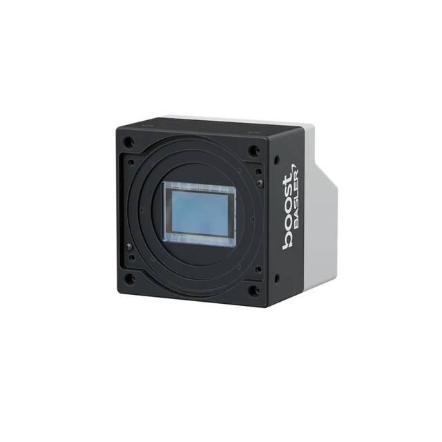
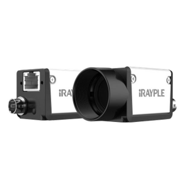
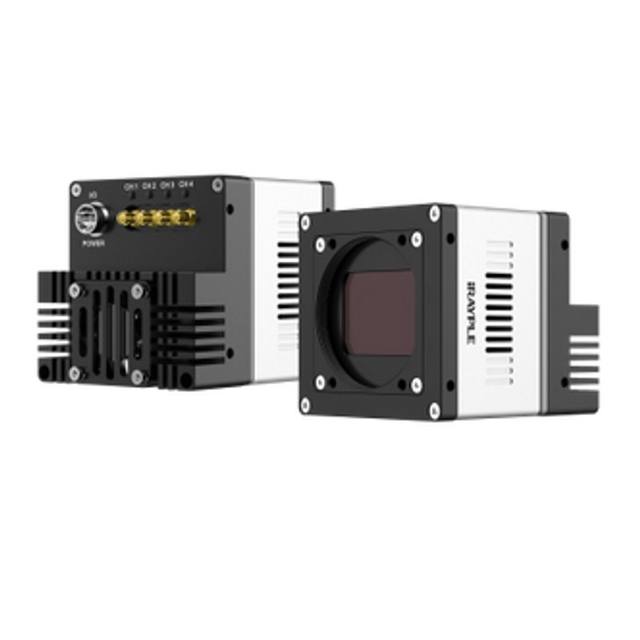
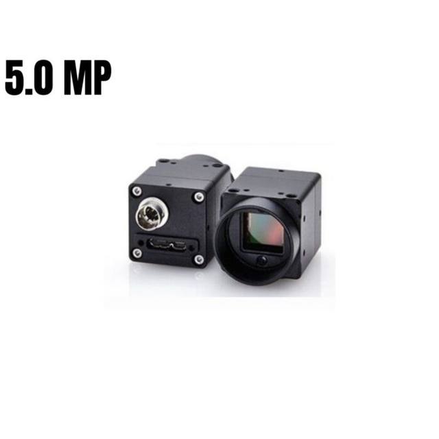
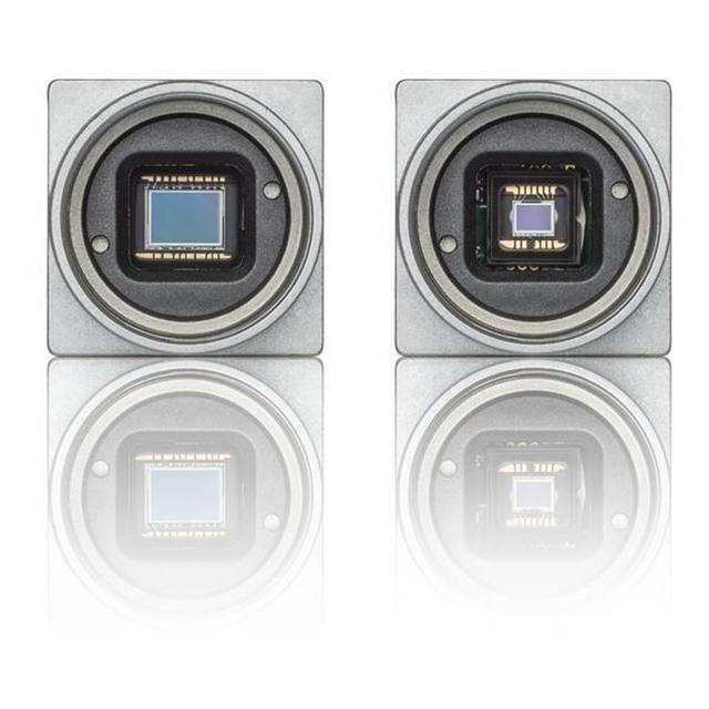
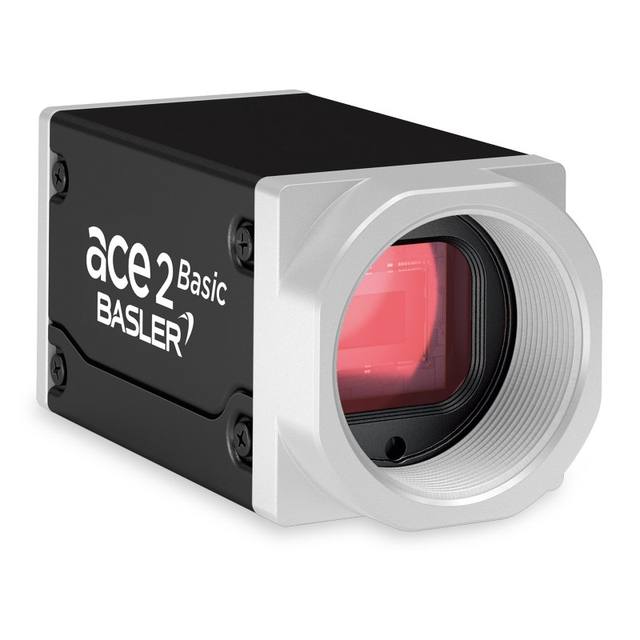
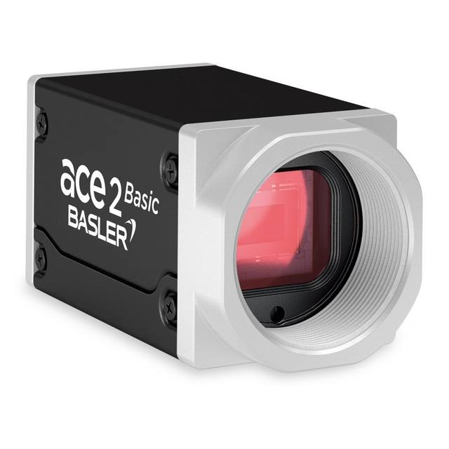
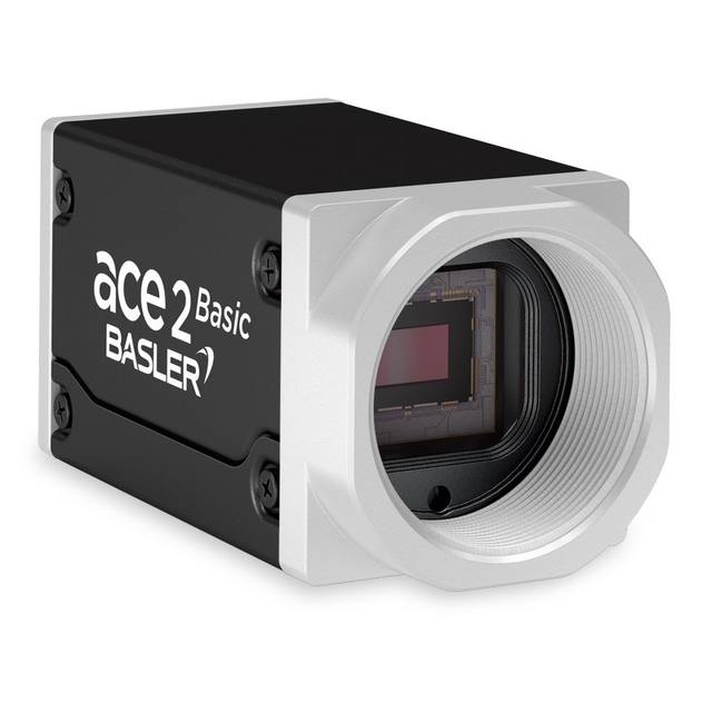
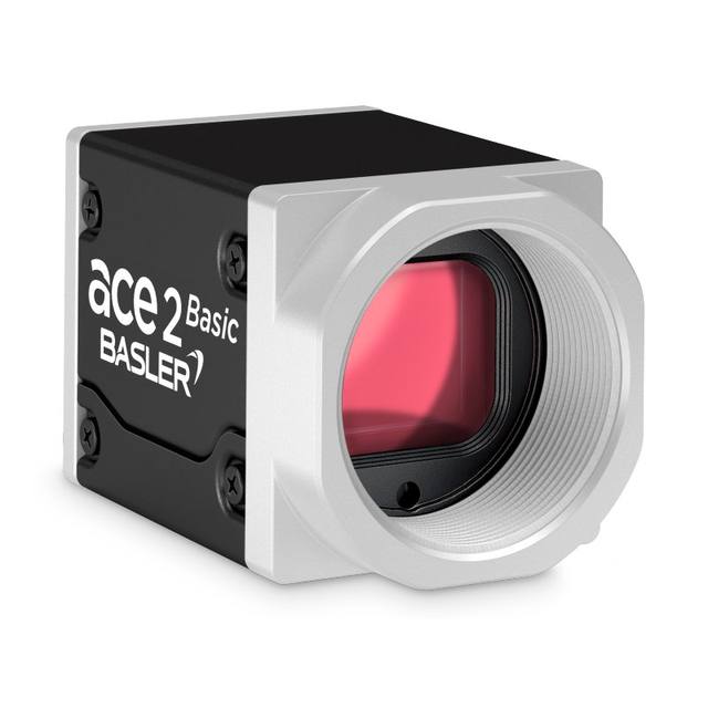
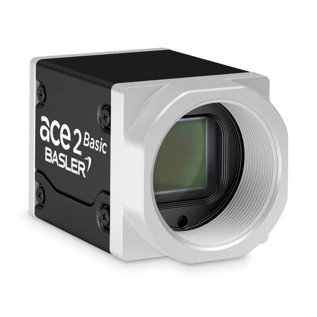
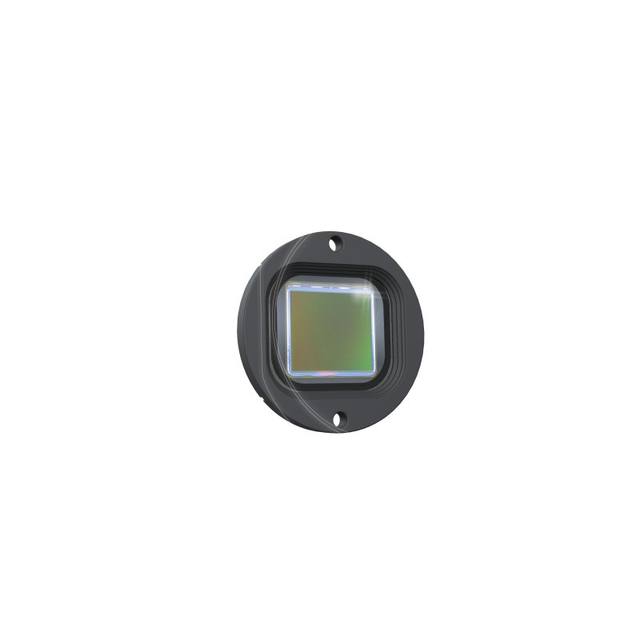
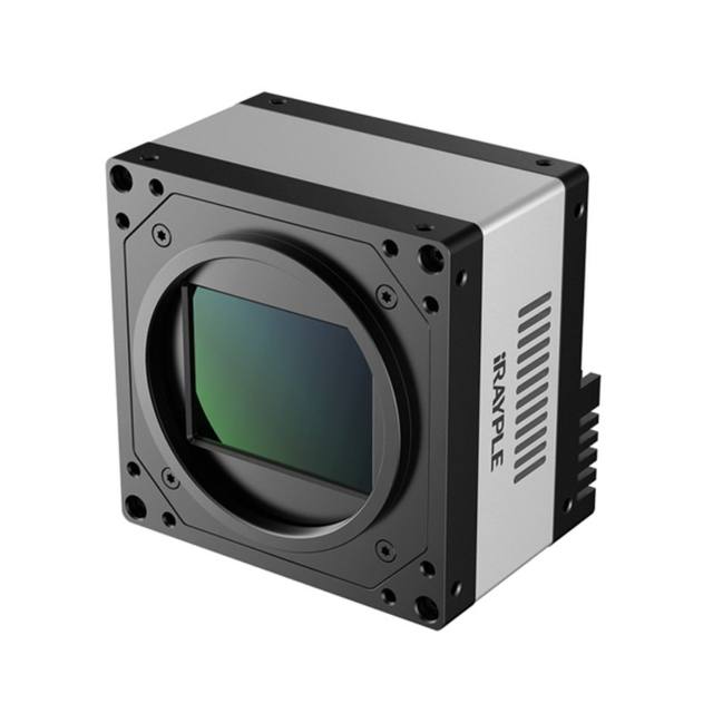
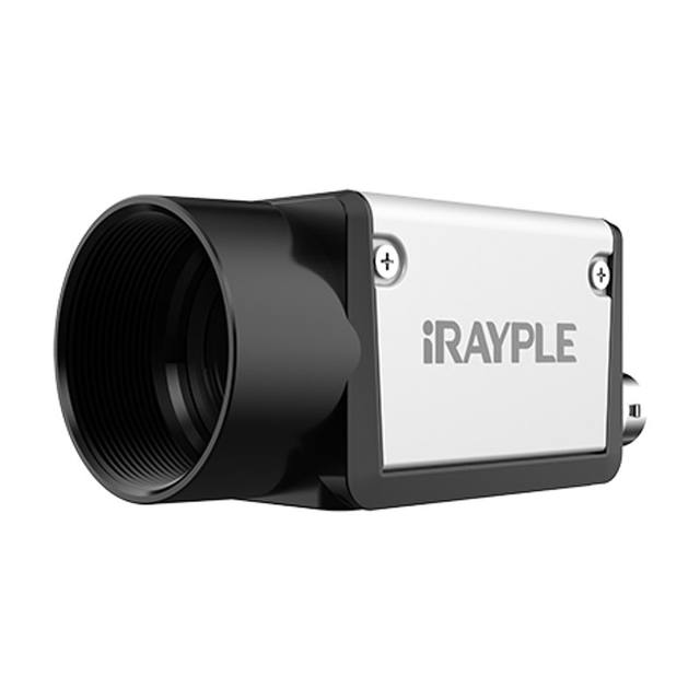
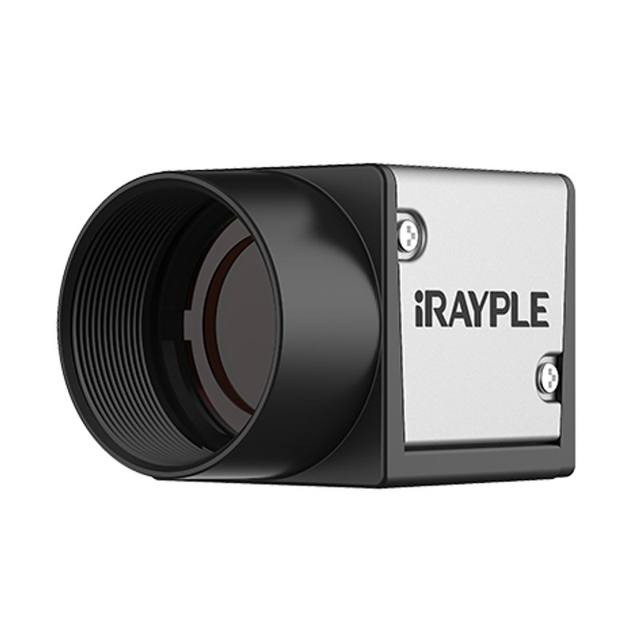
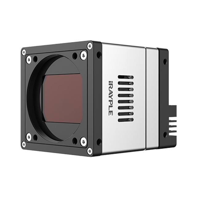
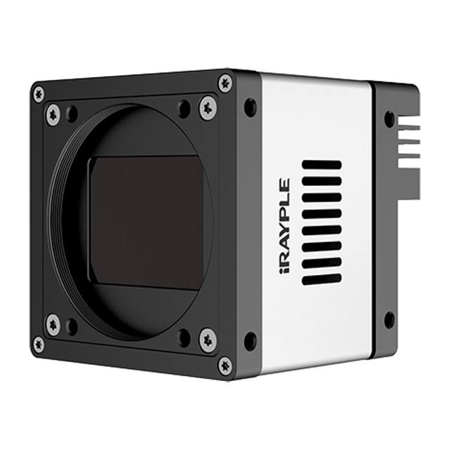
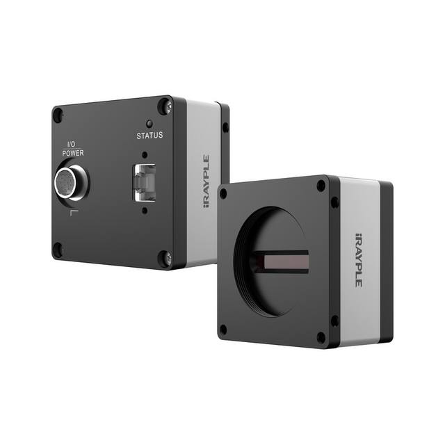
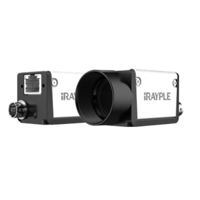
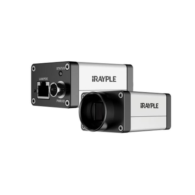
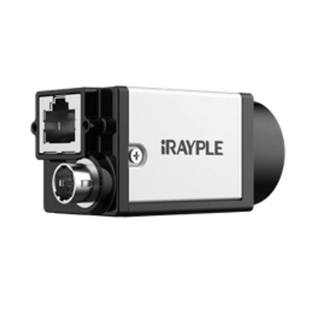
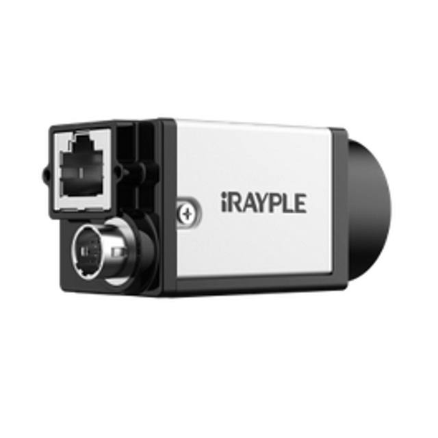
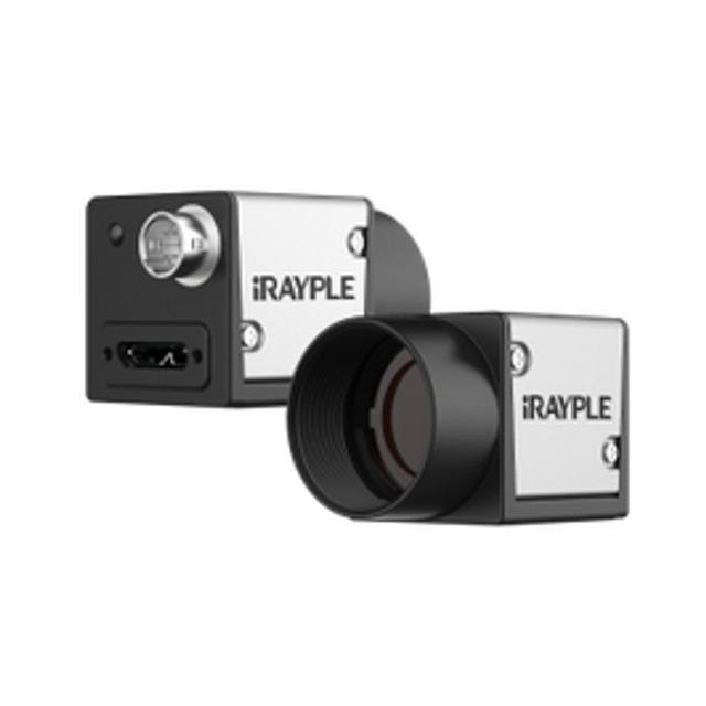
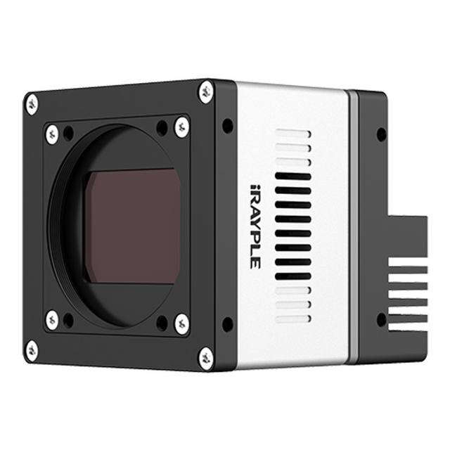
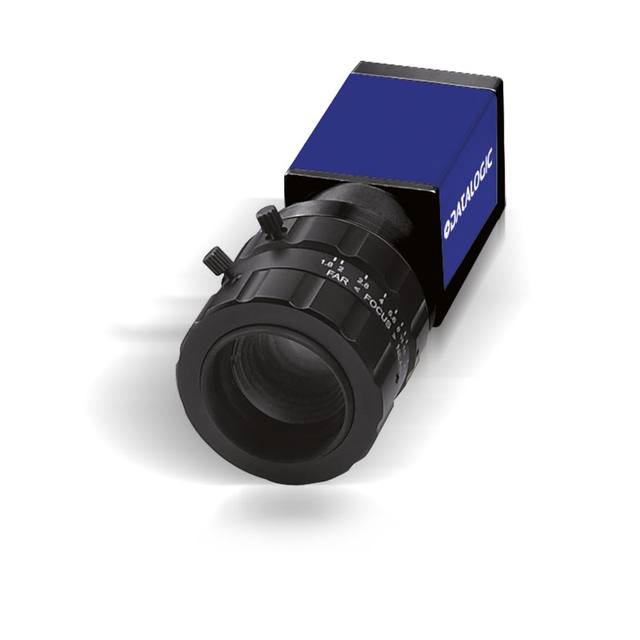
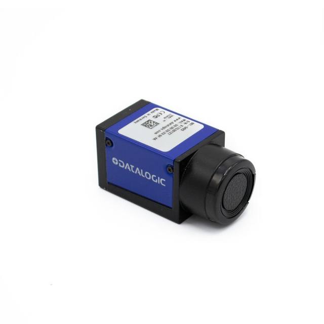
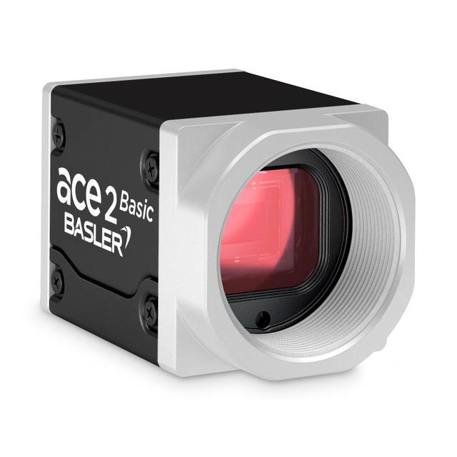
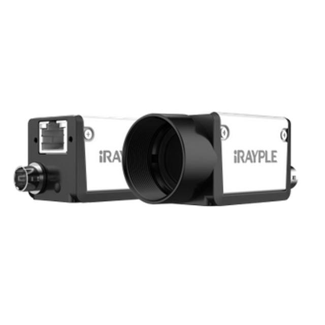
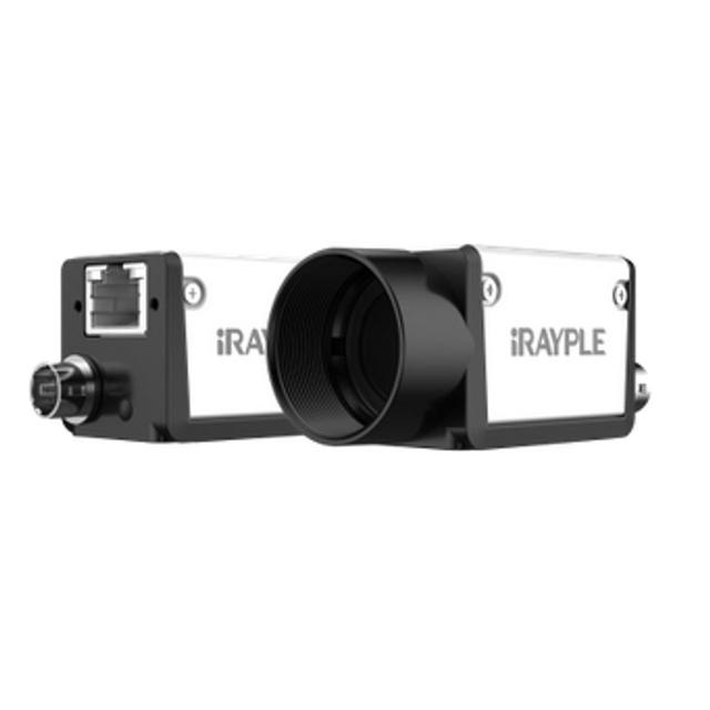
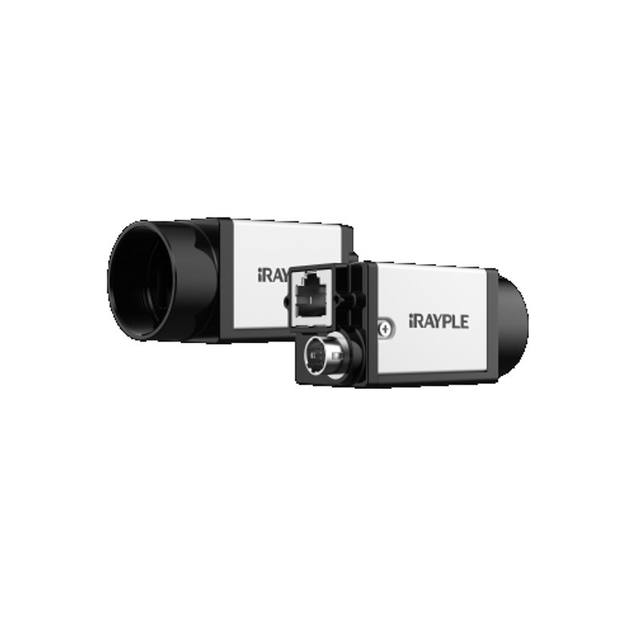
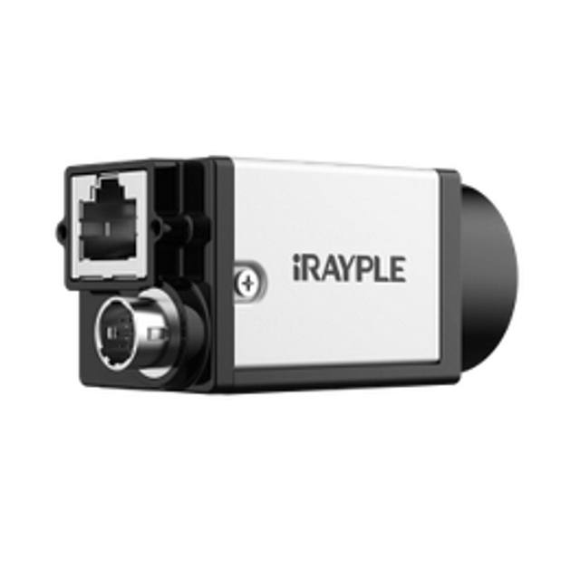
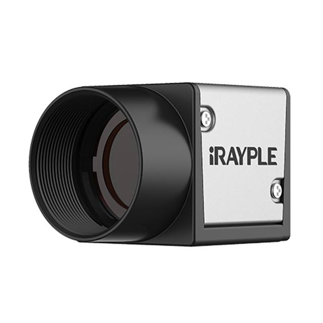
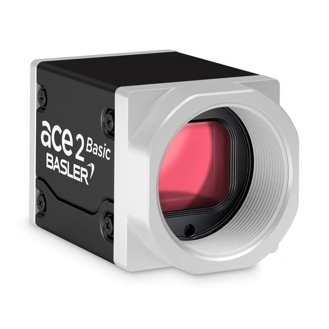
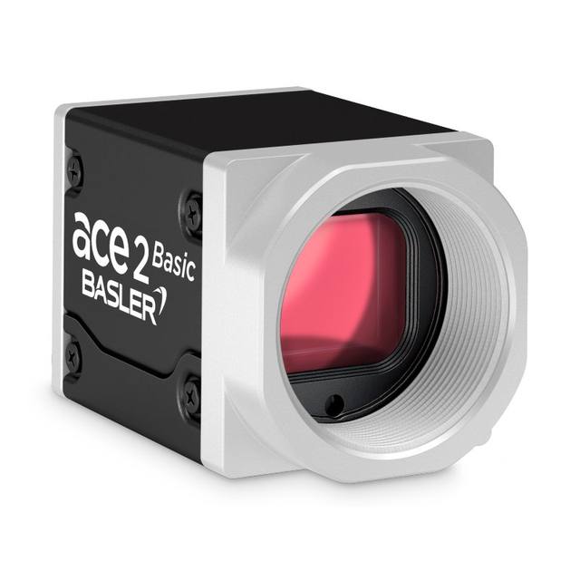
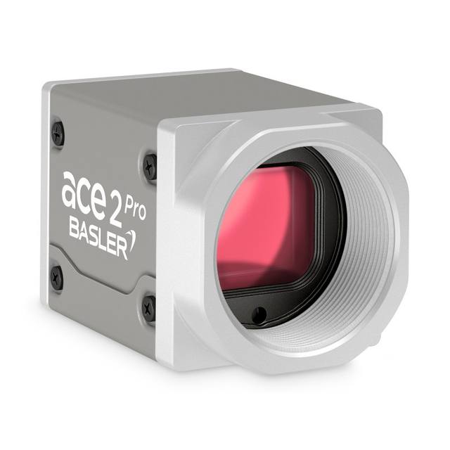
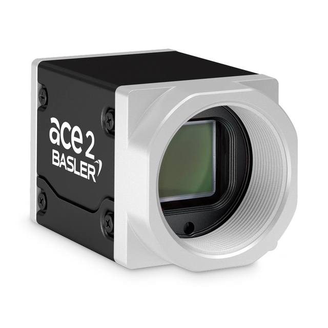
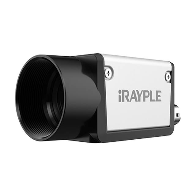
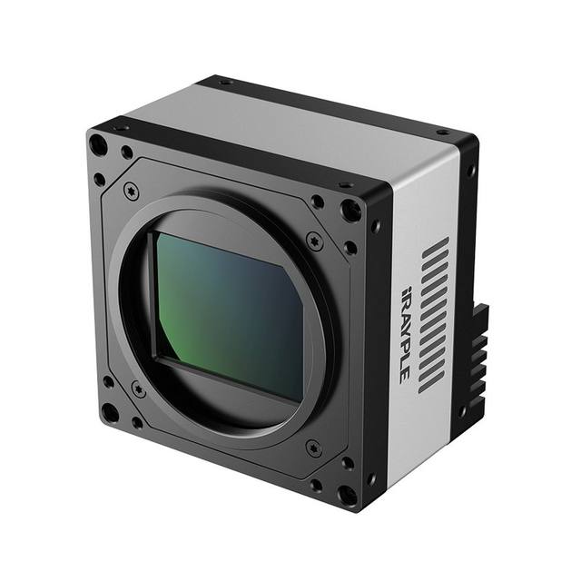
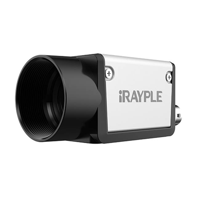
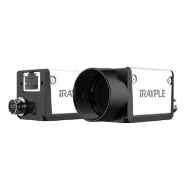
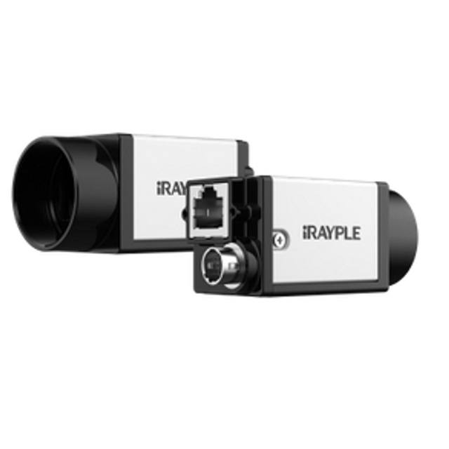
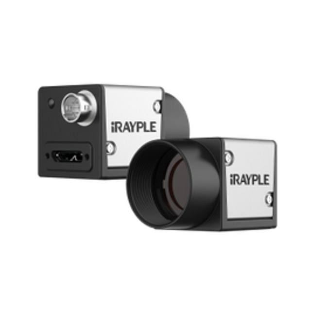
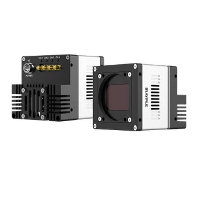
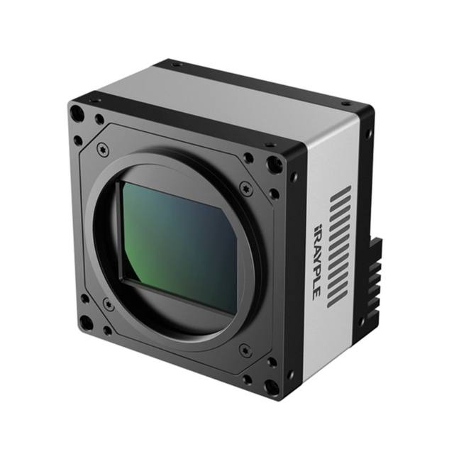
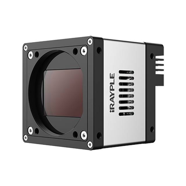
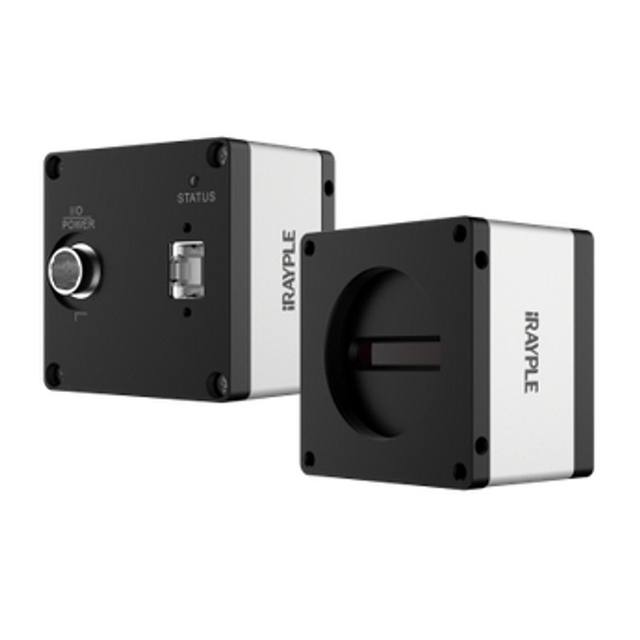
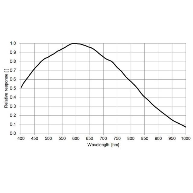
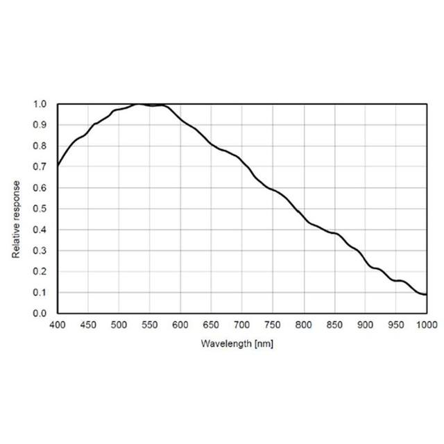
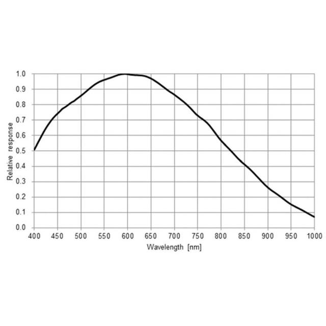
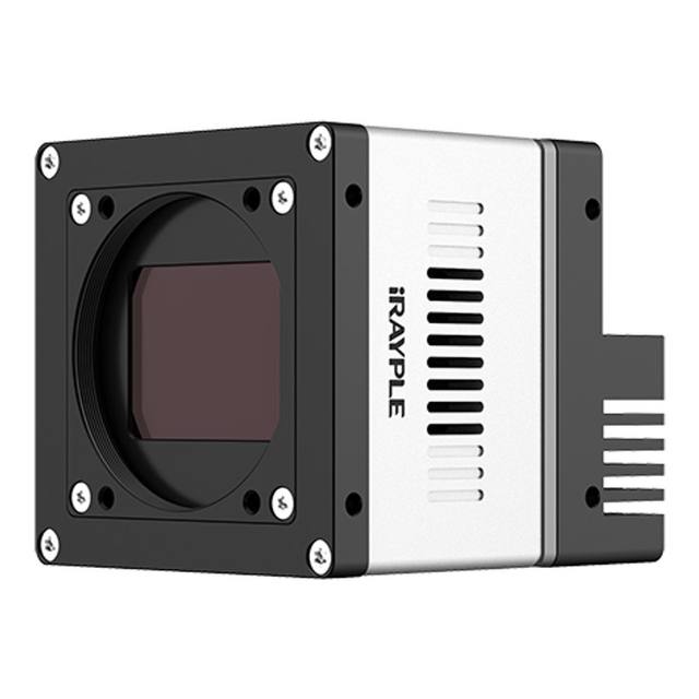
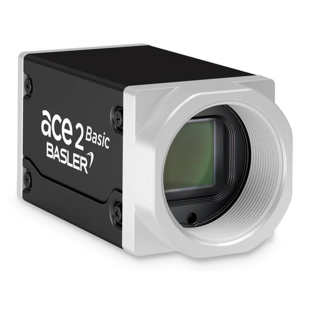
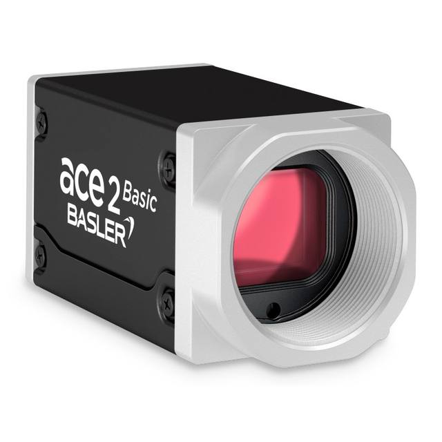
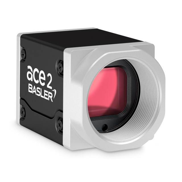
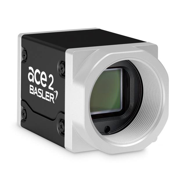
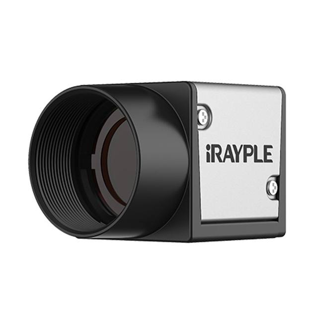
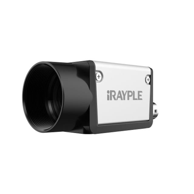
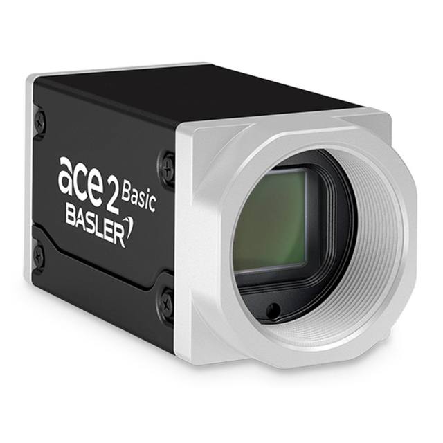
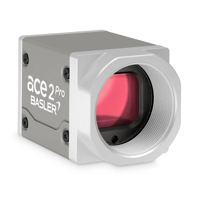
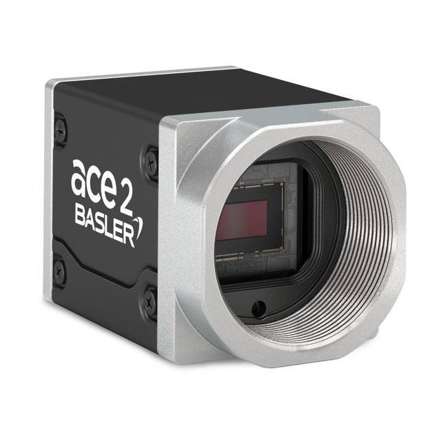
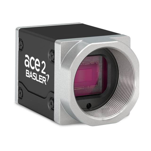
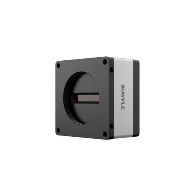
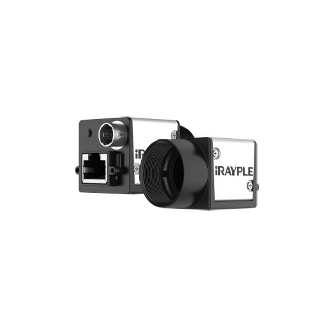
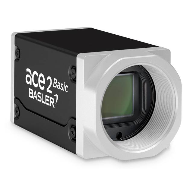
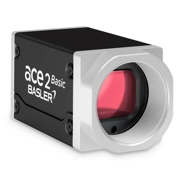
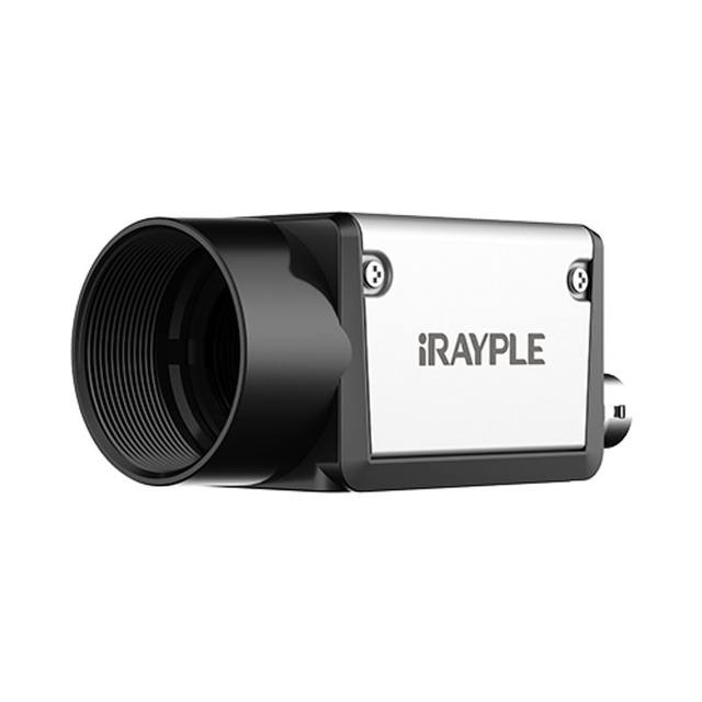
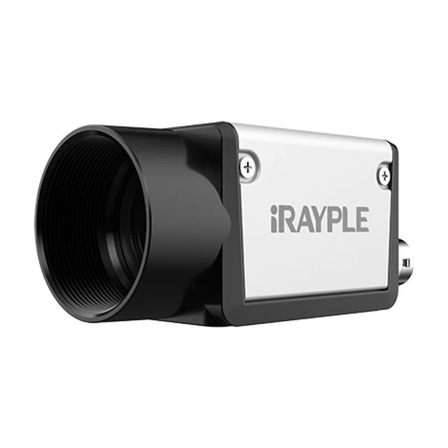
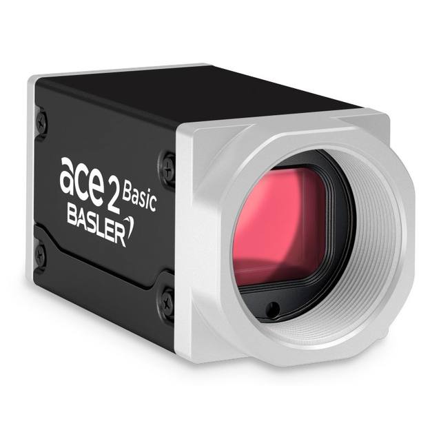
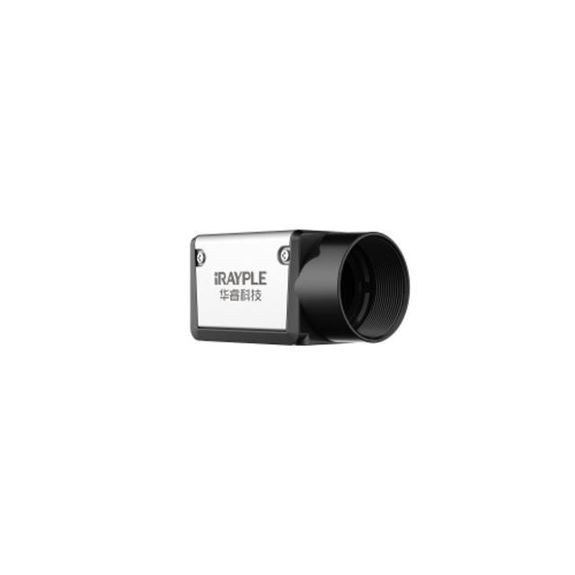
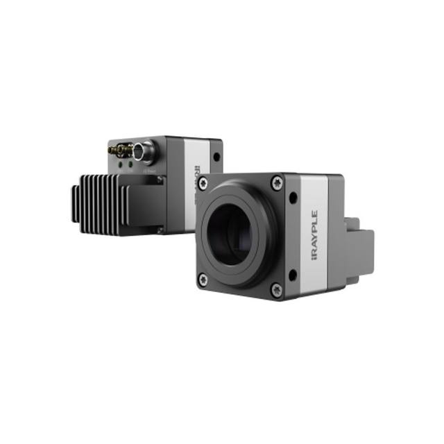
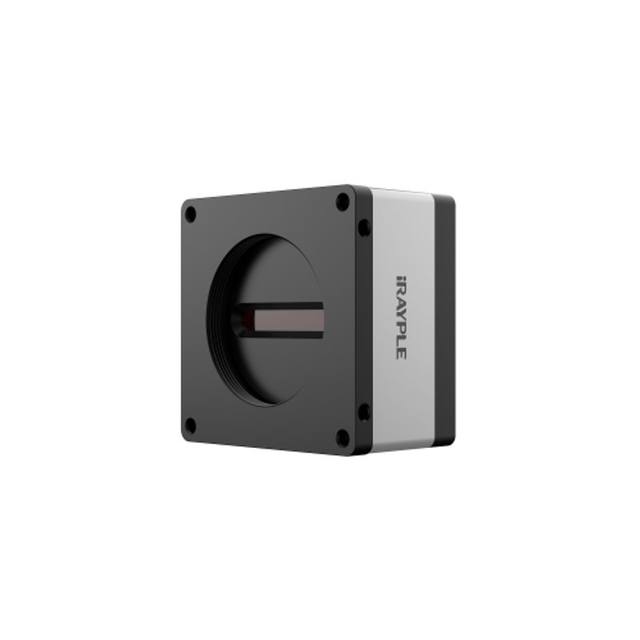
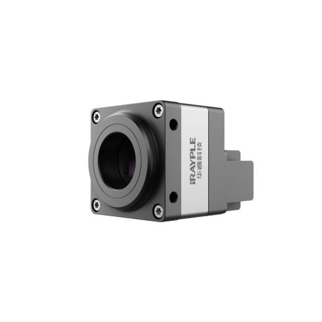
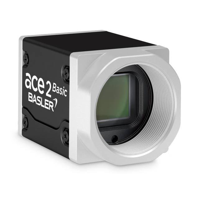
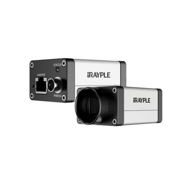
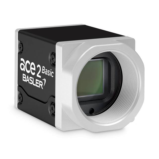
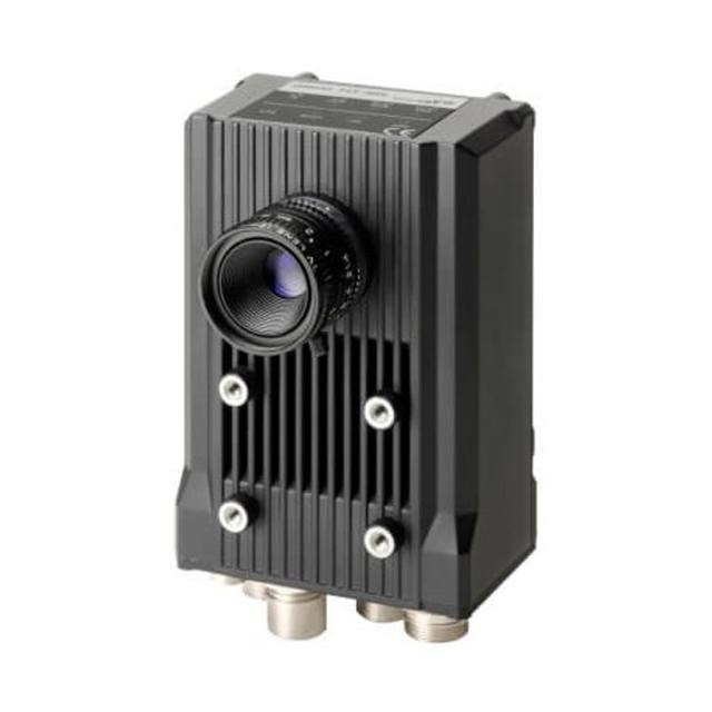
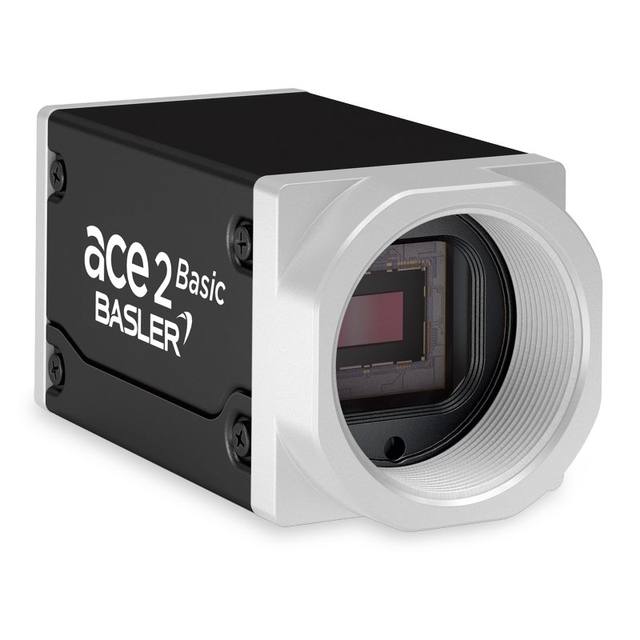
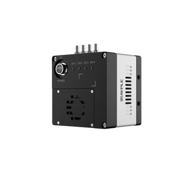
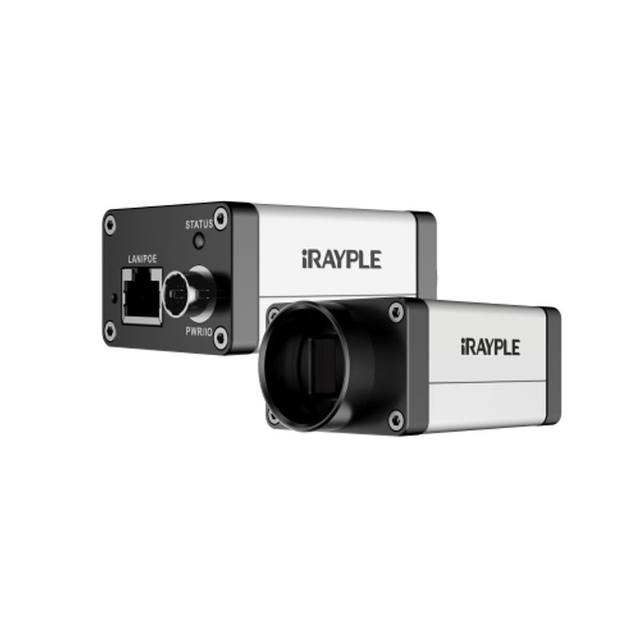
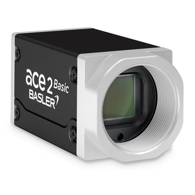
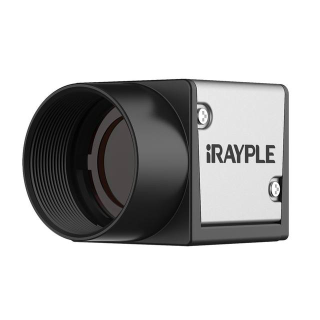
Monochrome sensors are the default for defect work: they have no Bayer colour filter, so they deliver higher effective resolution and sensitivity, and most surface defects are contrast features rather than colour features. Choose colour only when the defect is genuinely defined by colour (for example discoloration, wrong shade, or colour-coded components). For any part that moves during exposure, prefer a global-shutter sensor, which exposes all pixels simultaneously and avoids the geometric skew a rolling shutter introduces on moving objects. Modern global-shutter CMOS sensors (for example the Sony Pregius family used across Basler, iRAYPLE and Omron/Sentech (STC) cameras) are the workhorses here.
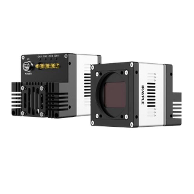
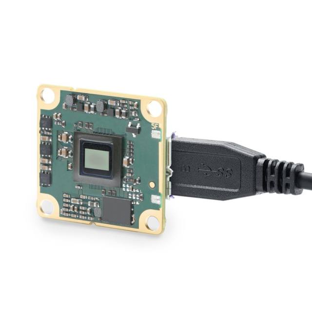
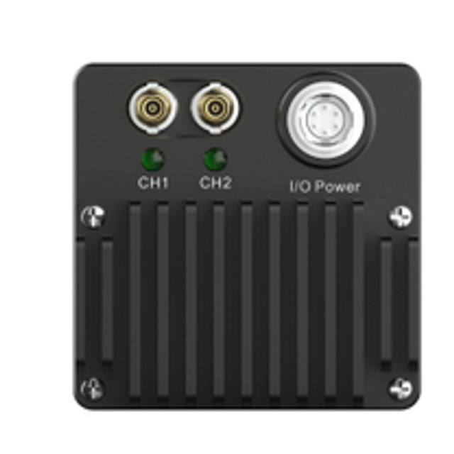
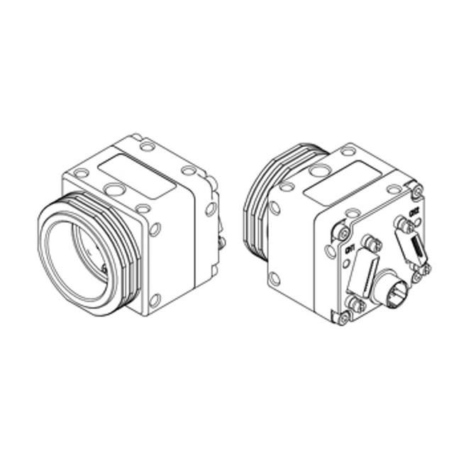
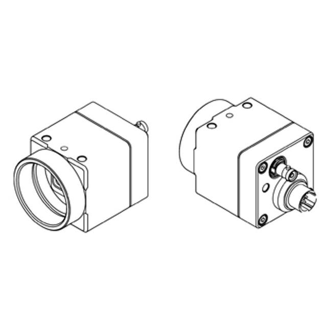
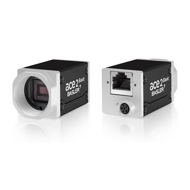
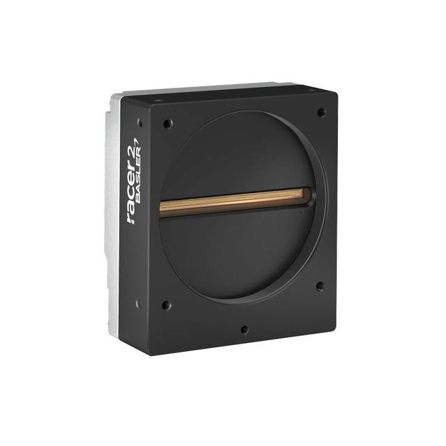
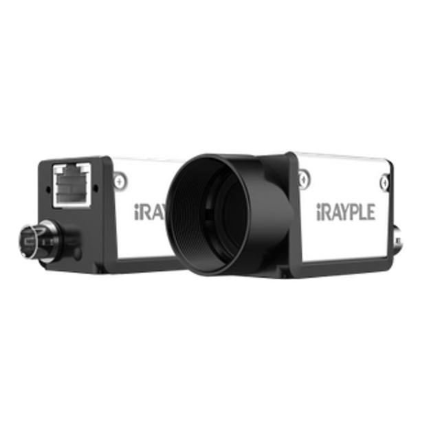
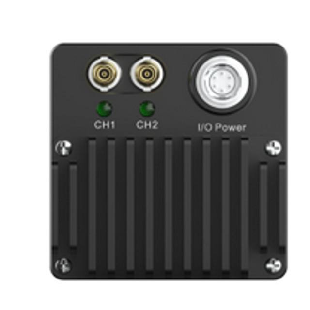
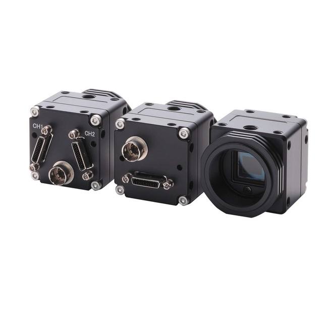
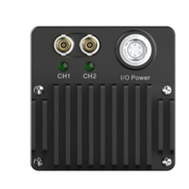
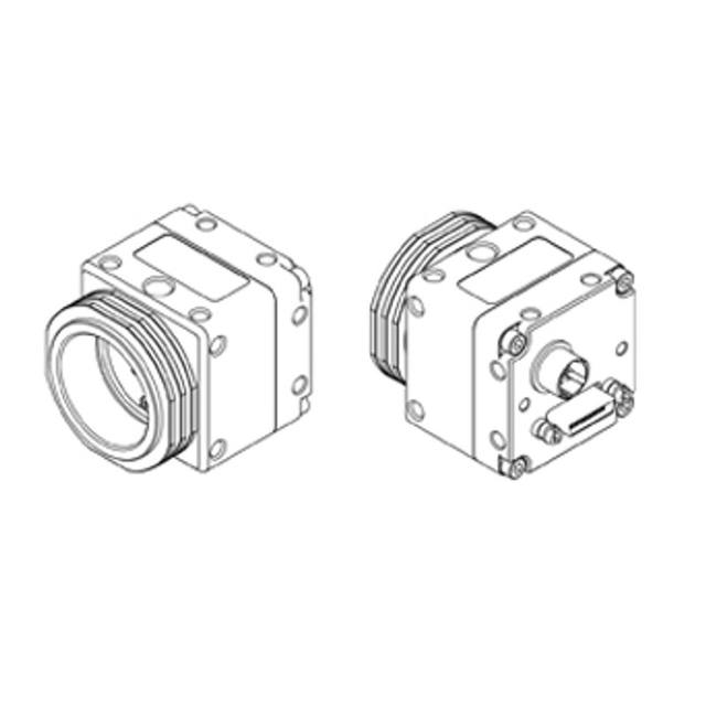
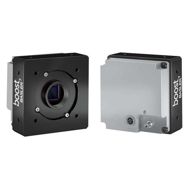
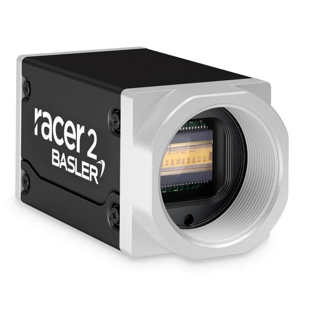
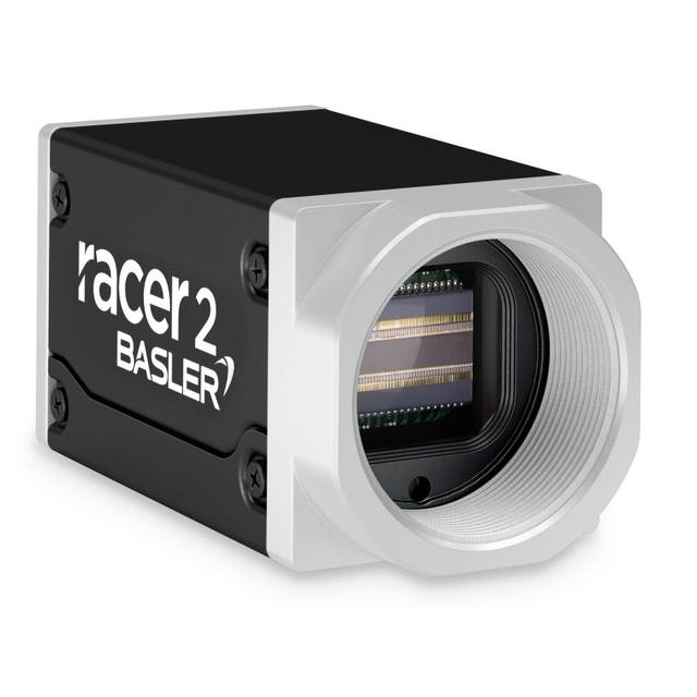
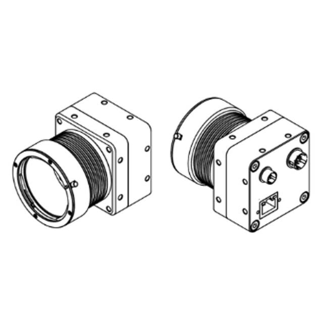
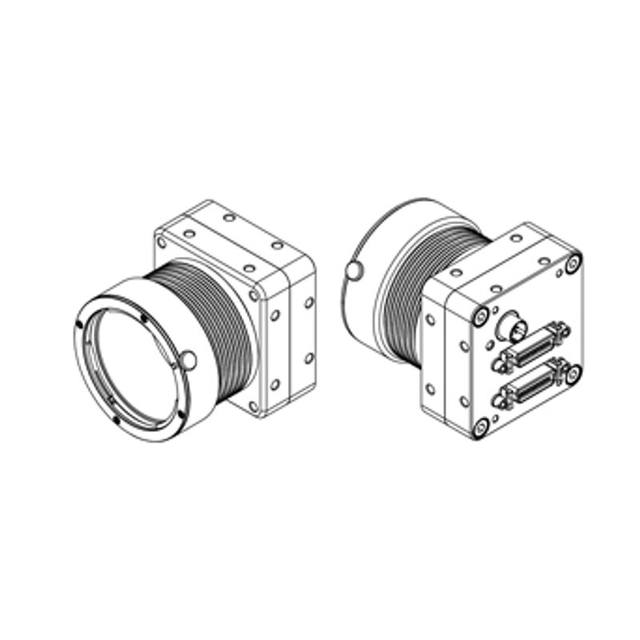
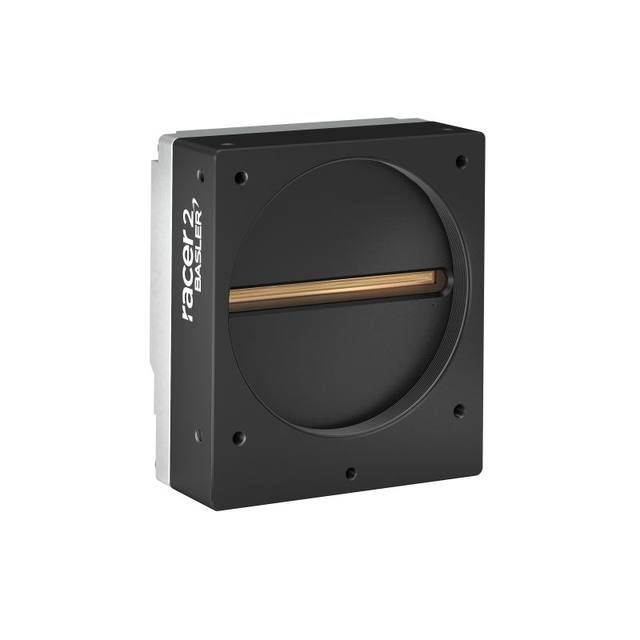
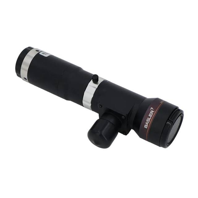
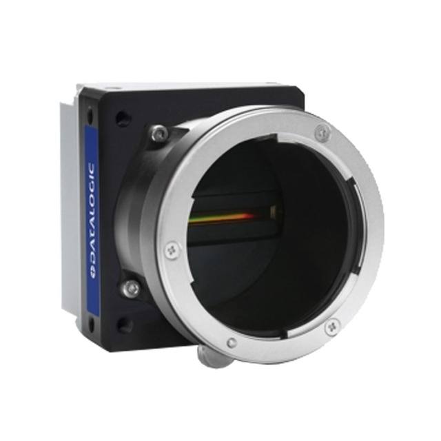
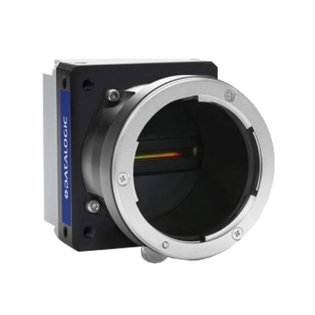
Interface follows resolution and speed. GigE Vision is the practical default for cable length and easy integration; USB3 Vision suits short, single-camera high-bandwidth links; CoaXPress and Camera Link are for the highest data rates and very high-resolution or high-frame-rate sensors. The catalog spans these interfaces across Basler, iRAYPLE and Omron/Sentech, so the camera can be matched to the bandwidth the inspection actually needs rather than over- or under-specified.
- Target several pixels (≈3–5) across the smallest defect, then size sensor resolution from the field of view.
- Default to monochrome for contrast defects; use colour only when colour defines the defect.
- Use a global shutter for moving parts to avoid motion skew.
- Match the interface (GigE / USB3 / CoaXPress / Camera Link) to the real bandwidth, not the headline number.
Lighting: the highest-leverage decision
Lighting is where most defect-inspection projects are won or lost, because the geometry of the illumination decides whether a defect shows up at all. The aim is to make the defect bright where the background is dark, or dark where the background is bright — a separable, repeatable signal. The right technique depends on the defect's physical nature, not on the part: a scratch, a dent and a stain on the same surface may each demand a different lighting geometry.
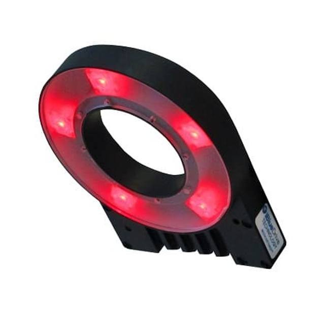
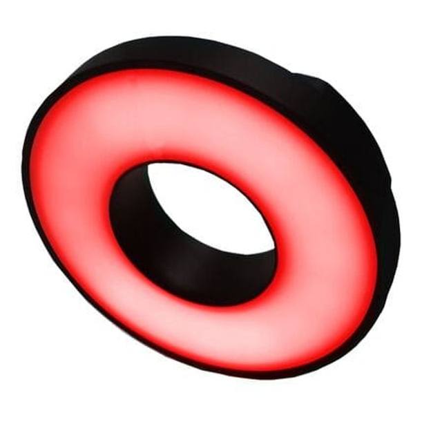
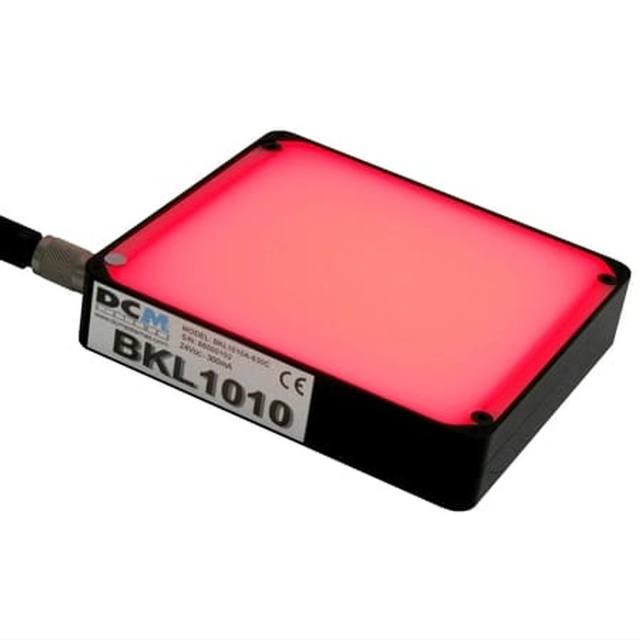
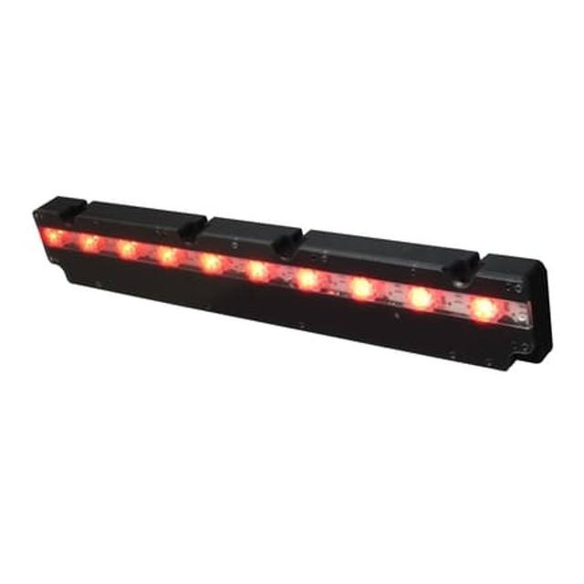
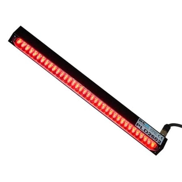
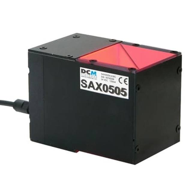
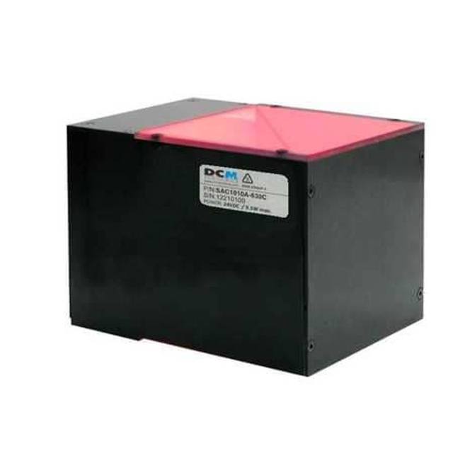
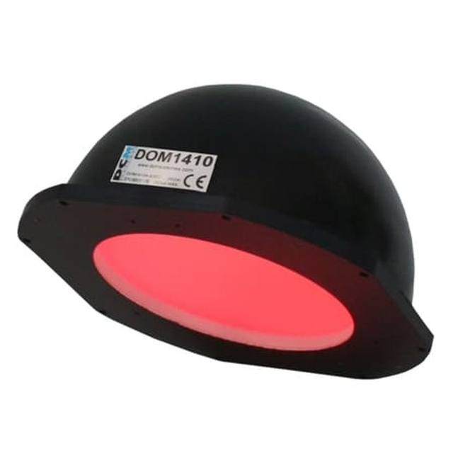
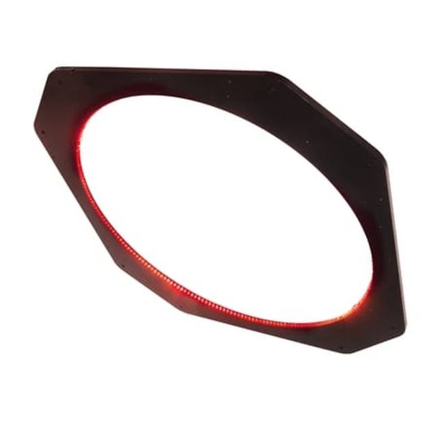
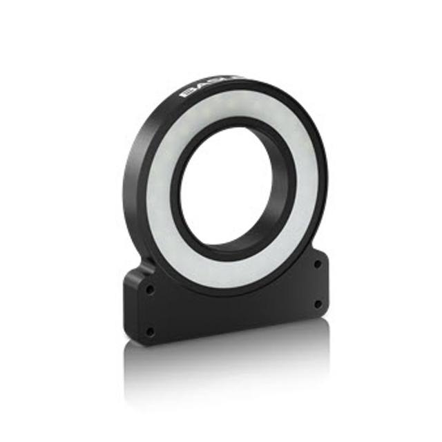
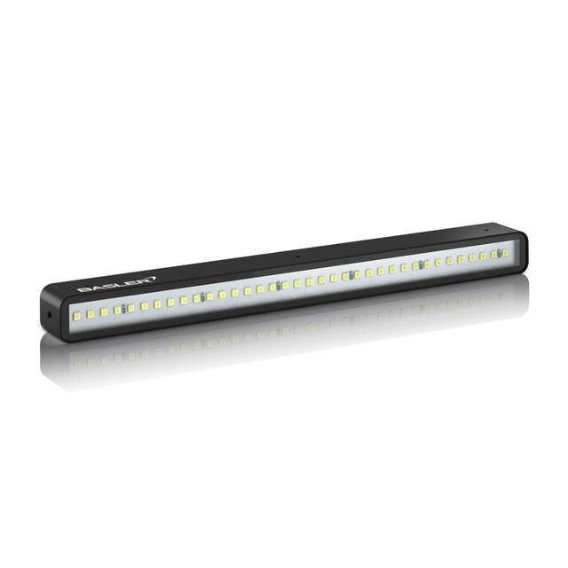
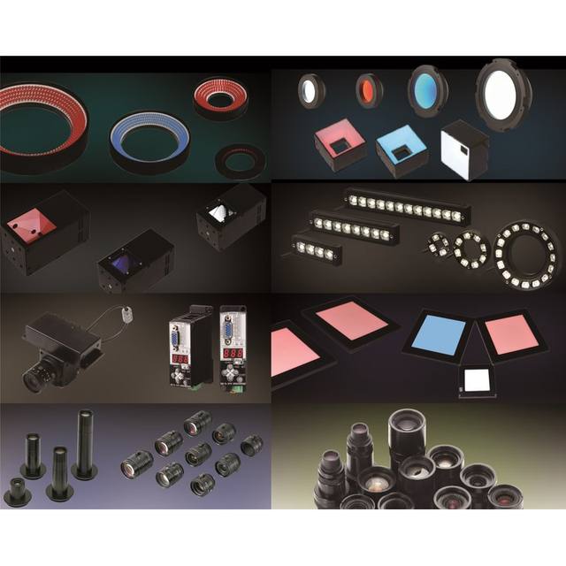
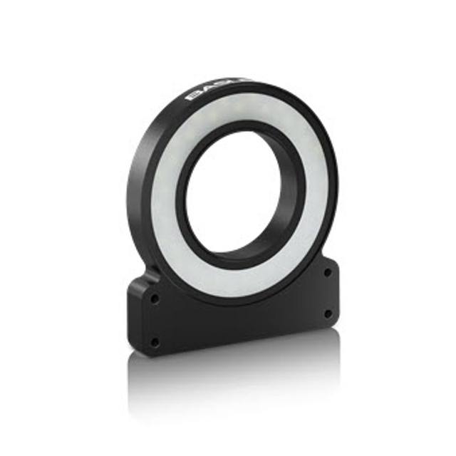
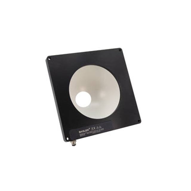
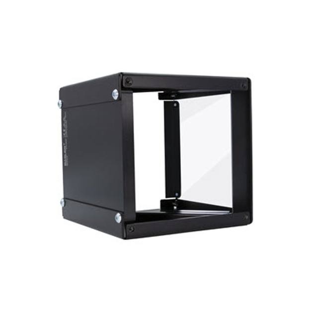
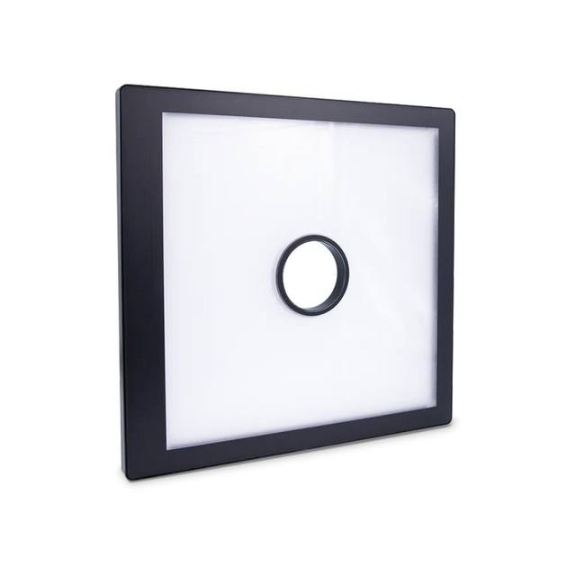
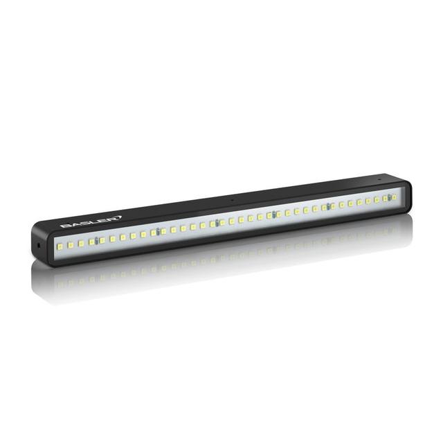
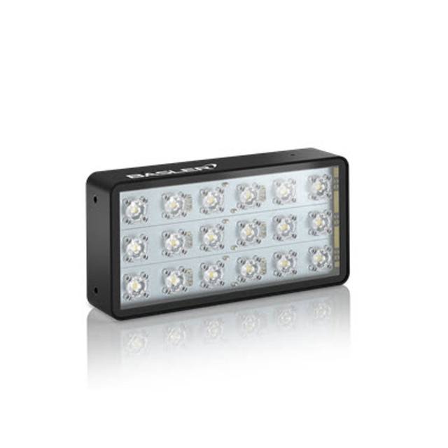
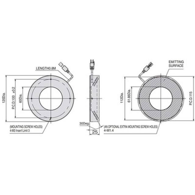
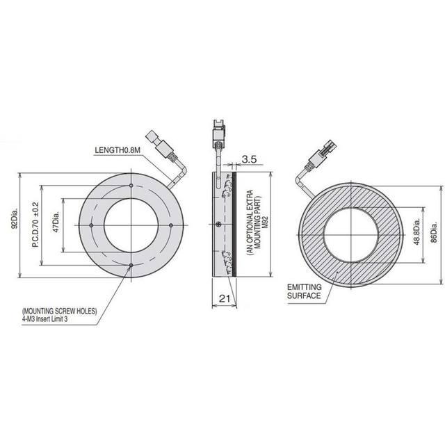
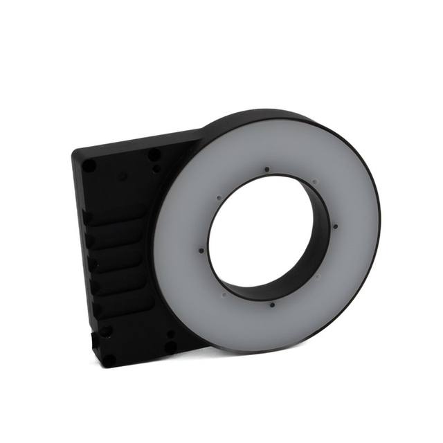
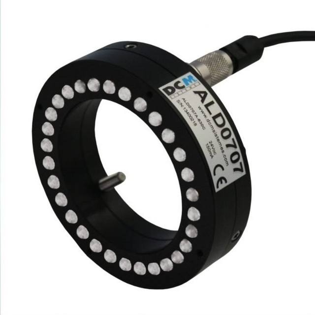
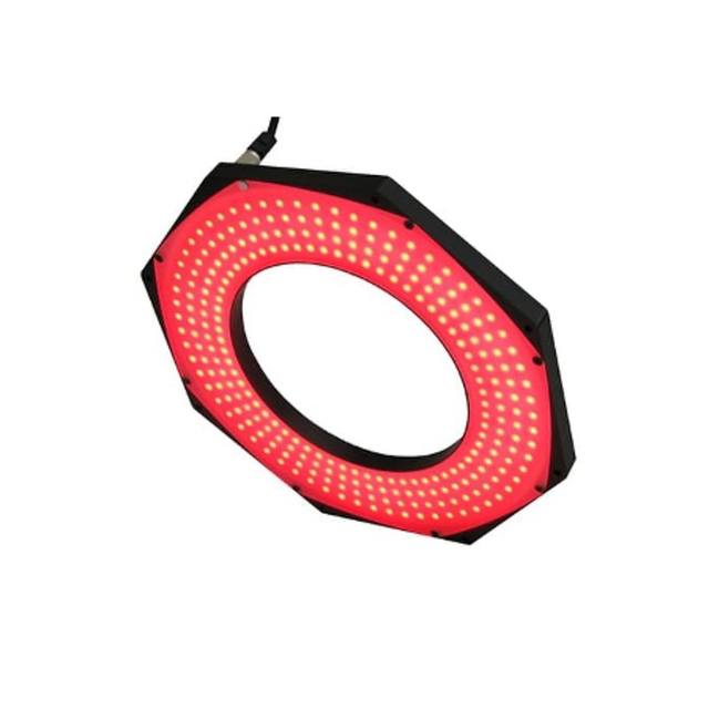
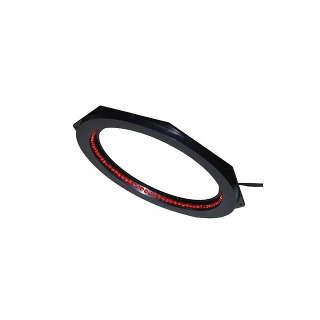
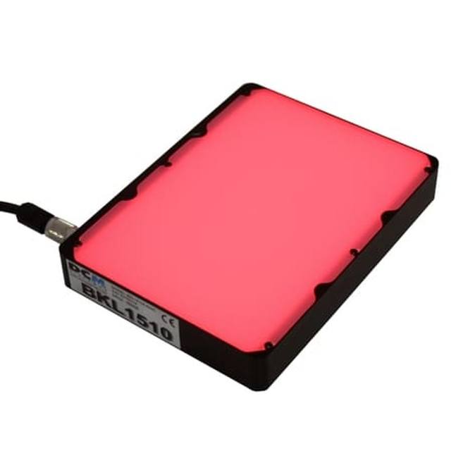
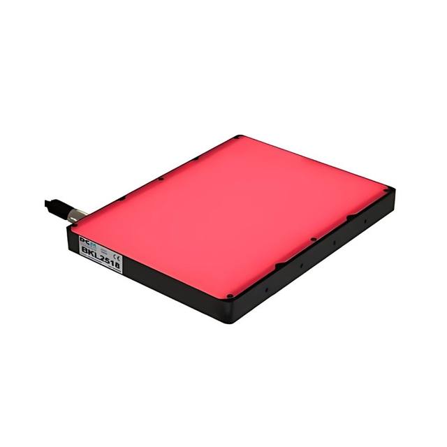
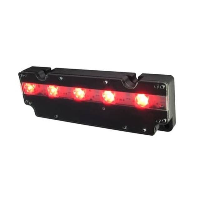
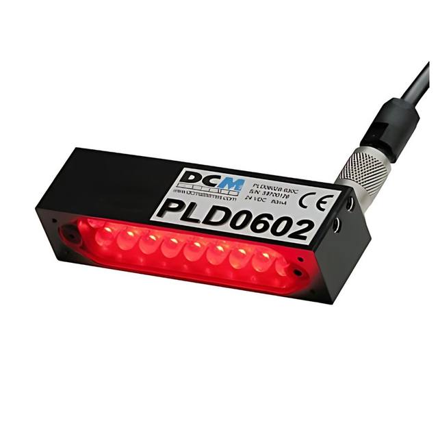
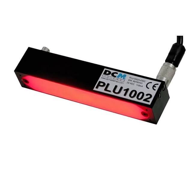
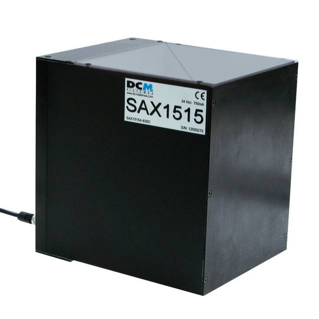
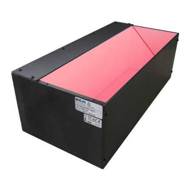
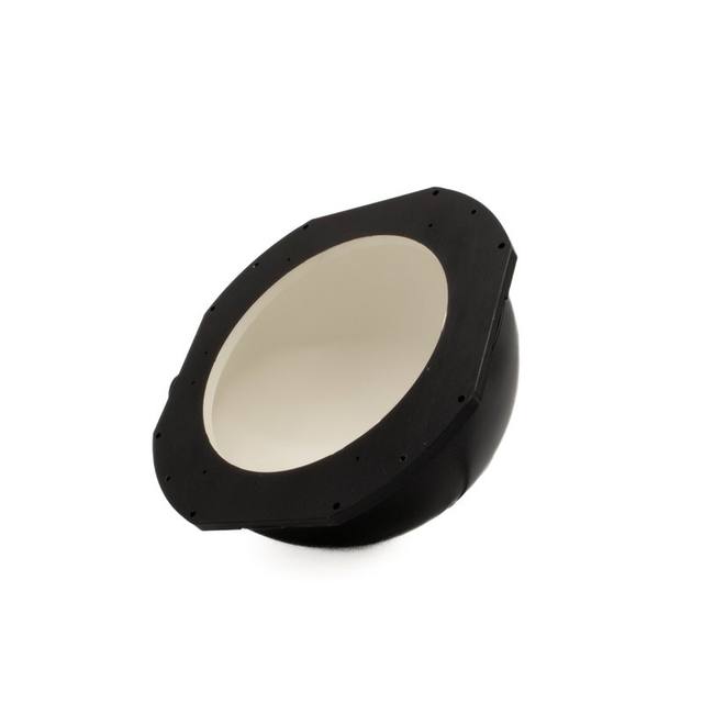
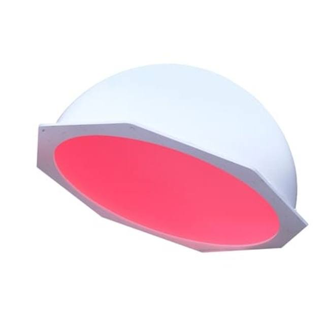
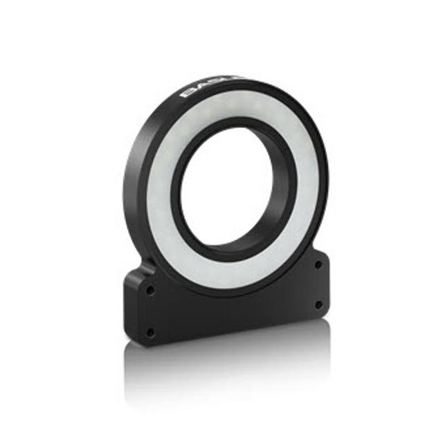
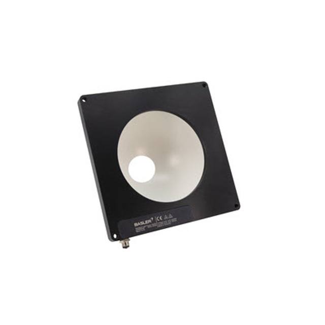
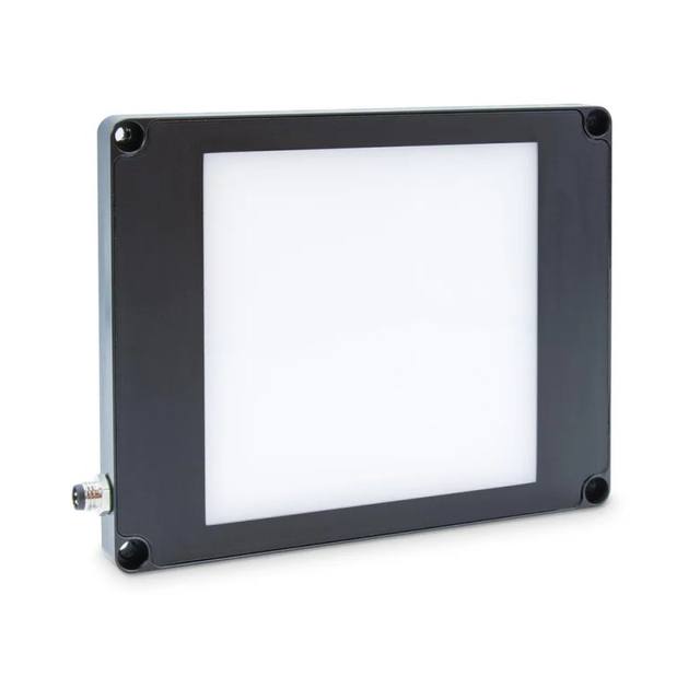
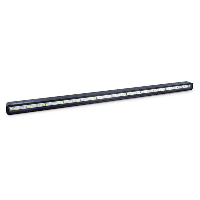
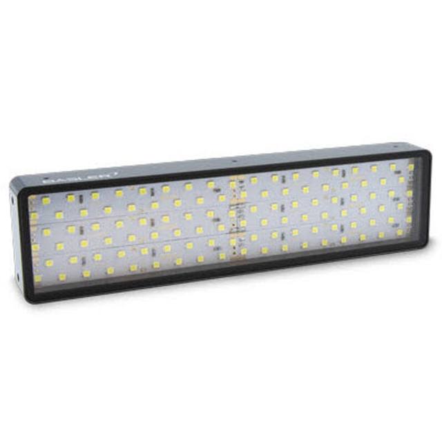
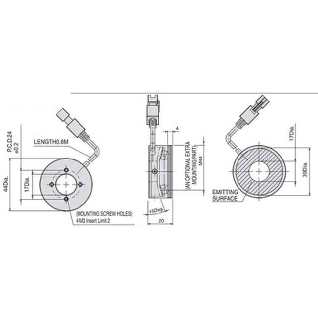
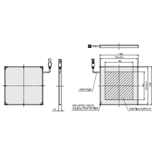
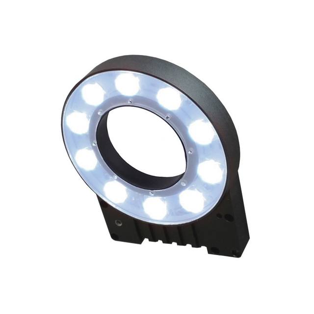
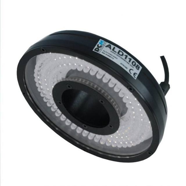
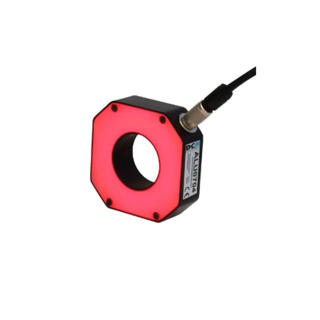
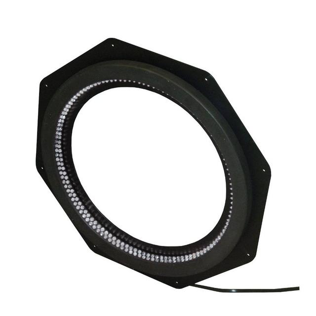
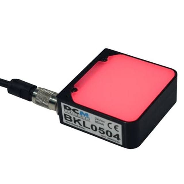
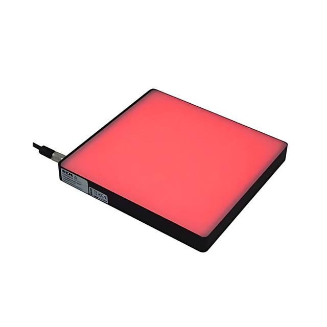
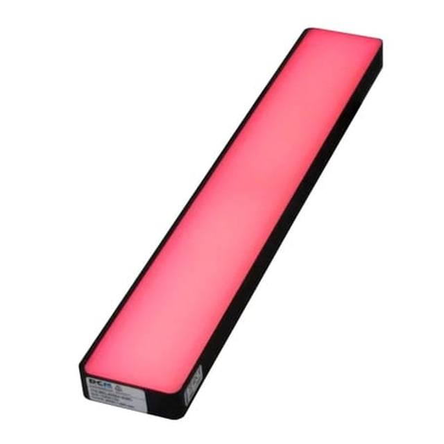
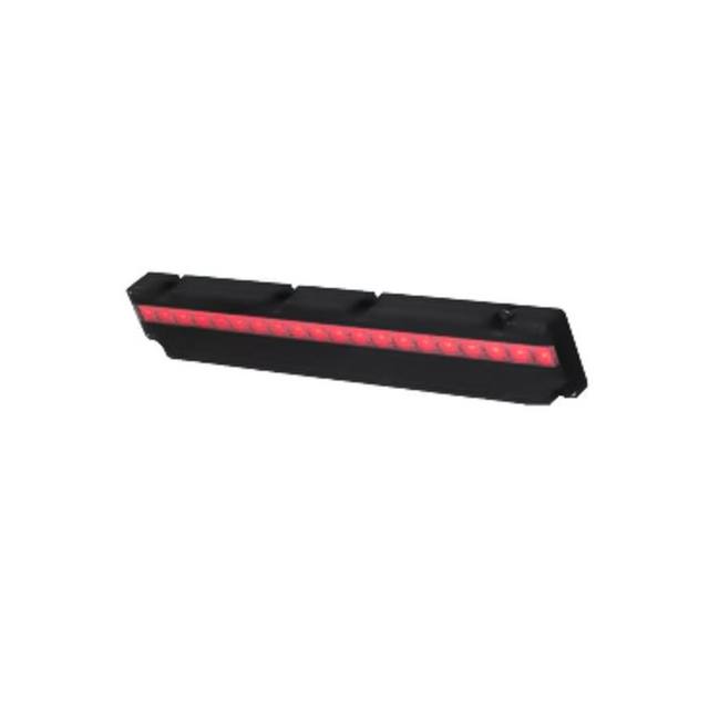
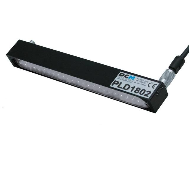
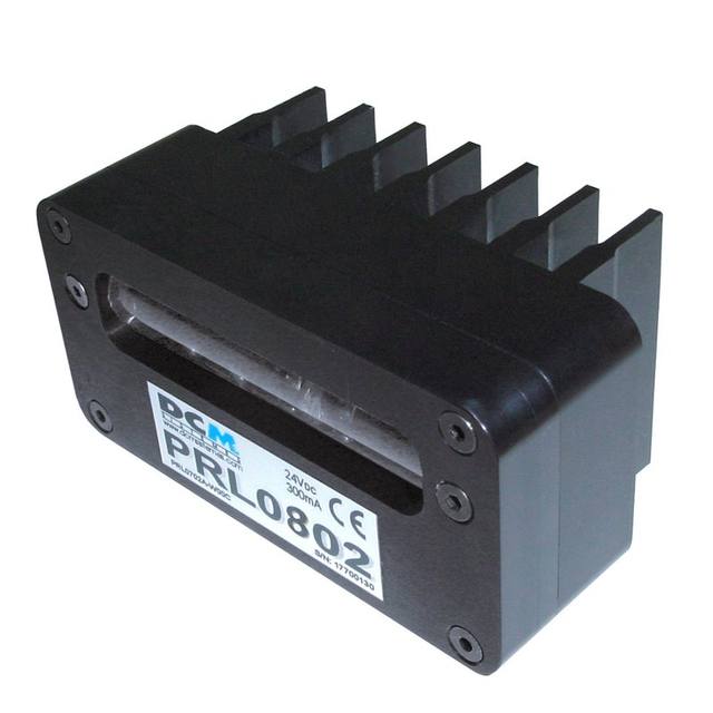
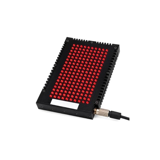
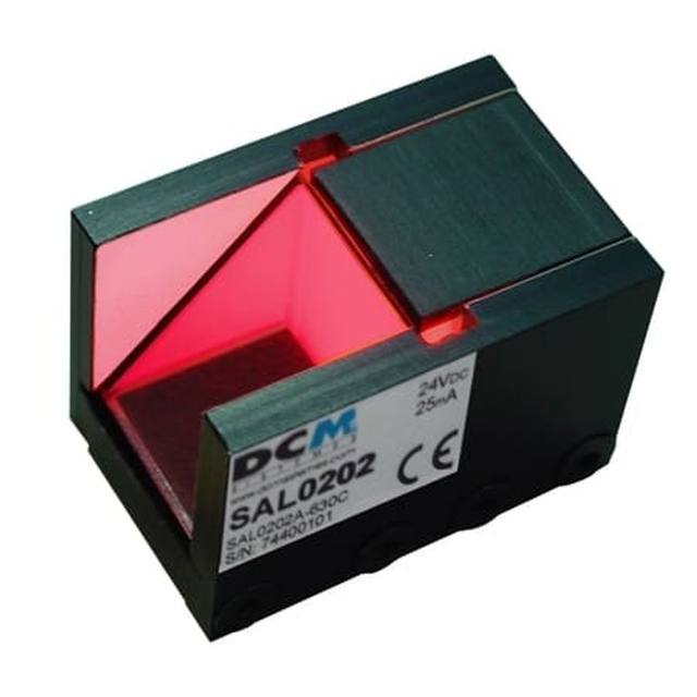
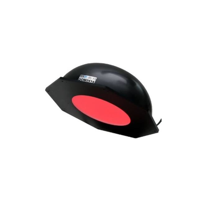
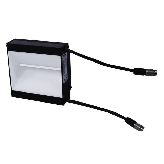
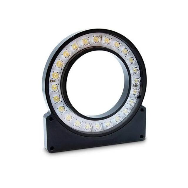
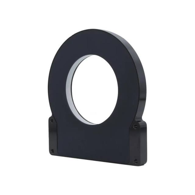
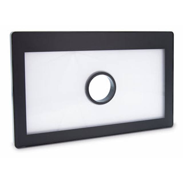
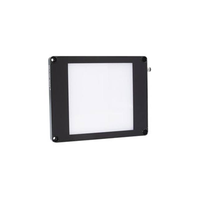
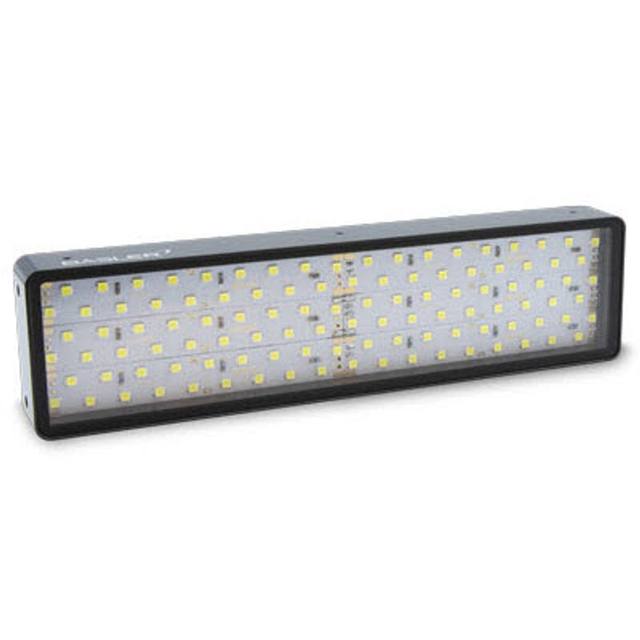
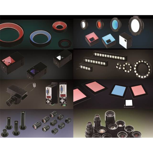
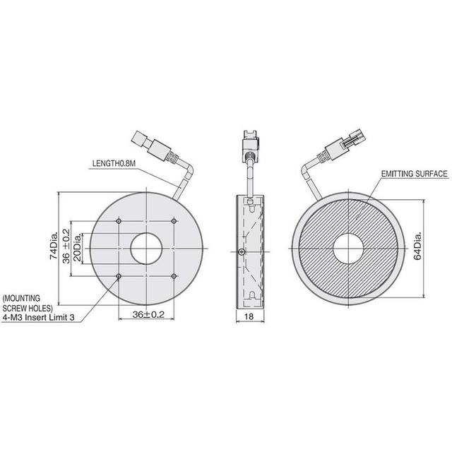
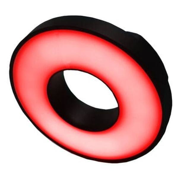
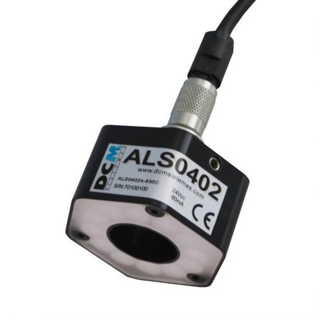
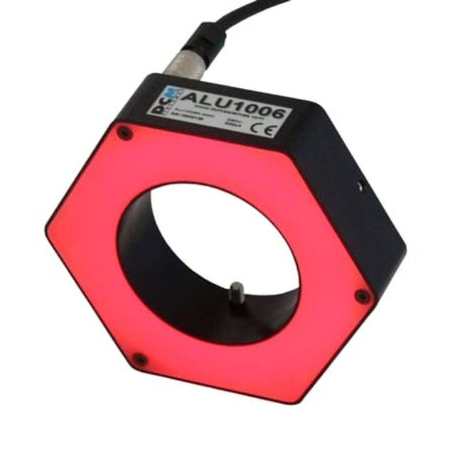
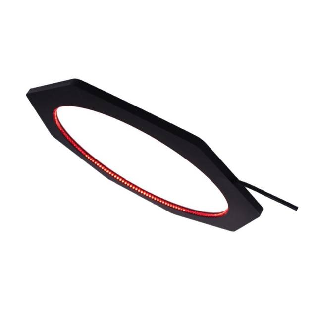
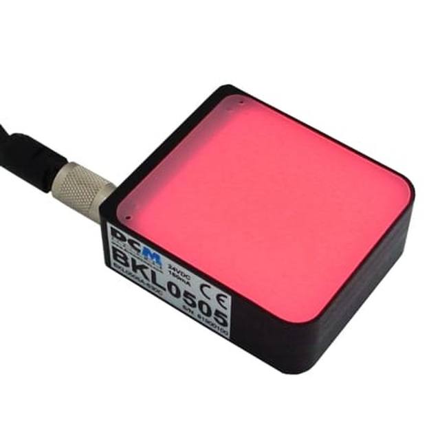
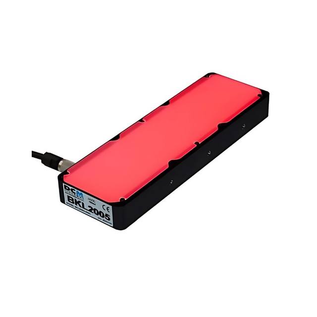
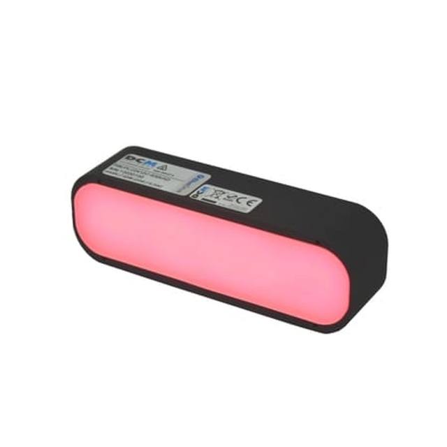
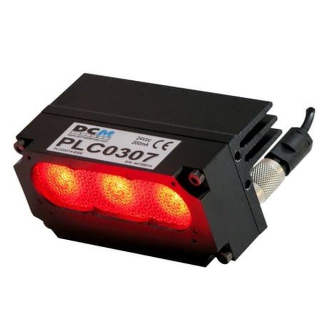
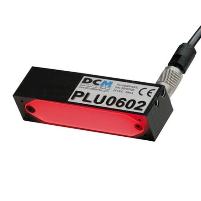
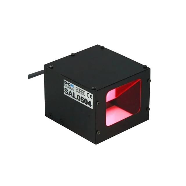
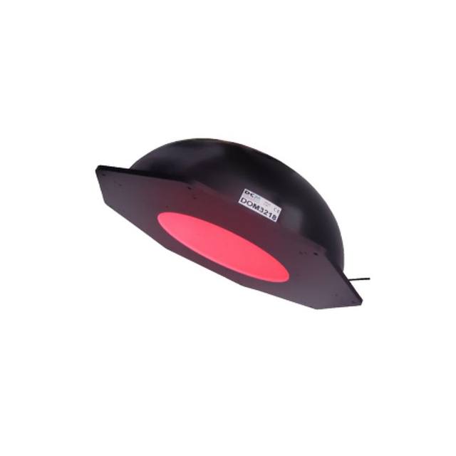
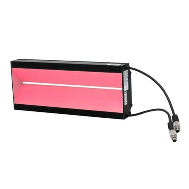
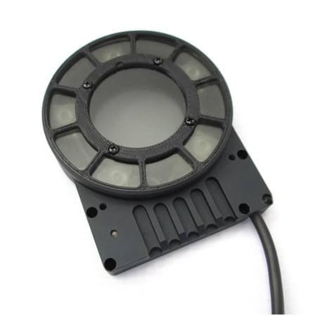
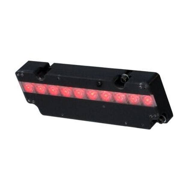
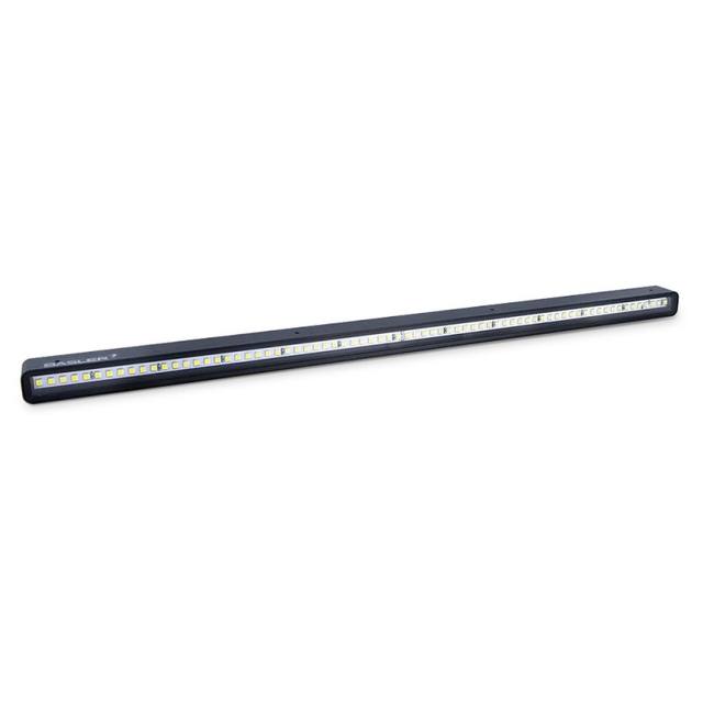
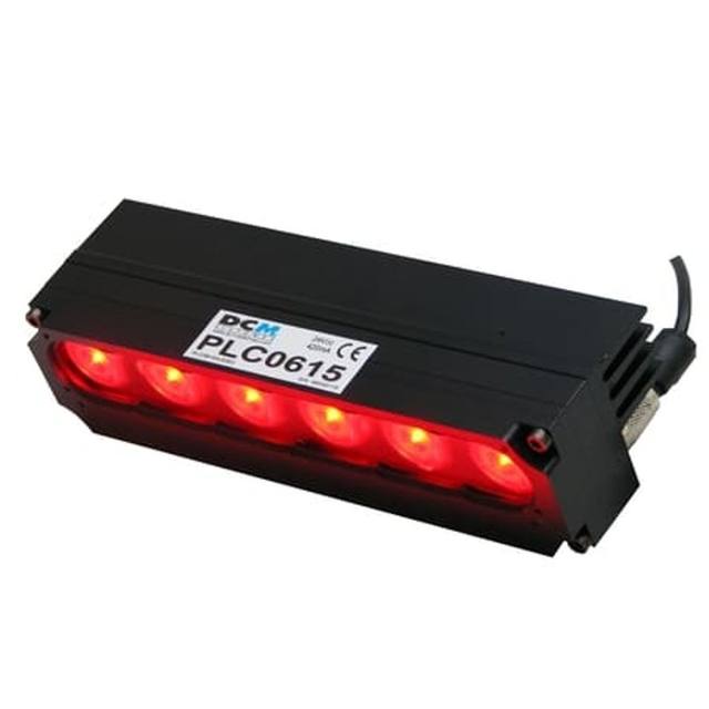
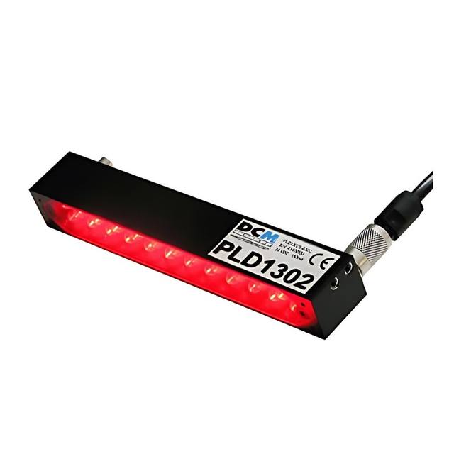
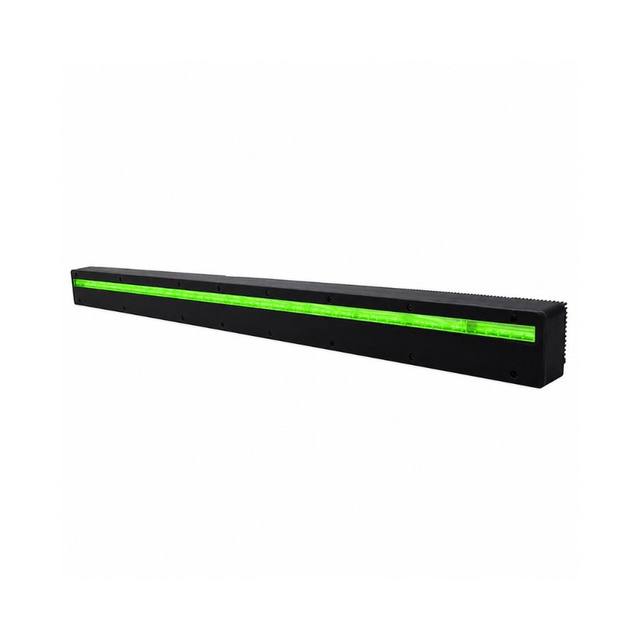
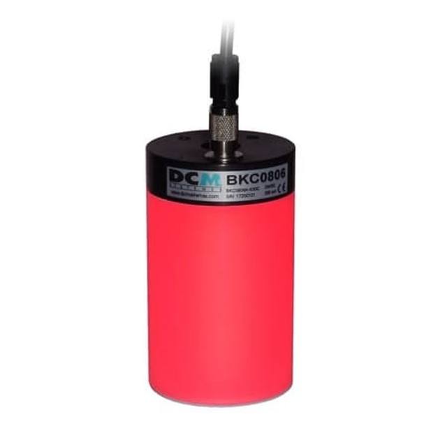
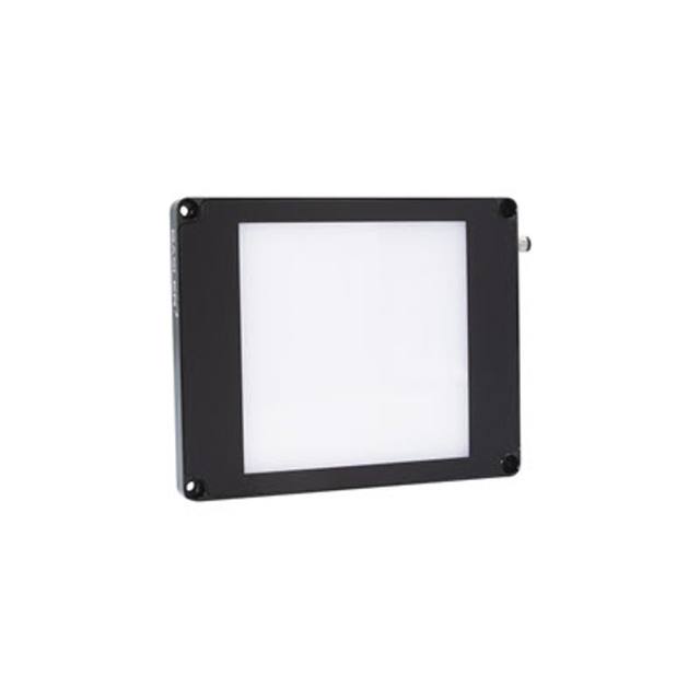
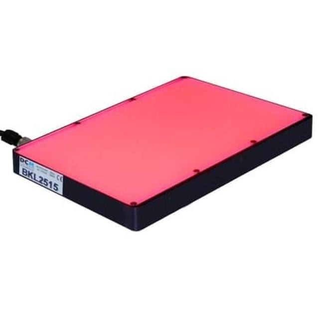
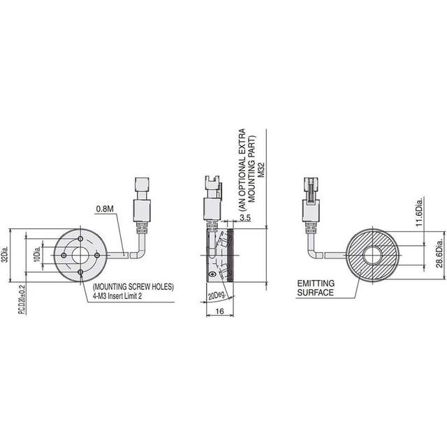
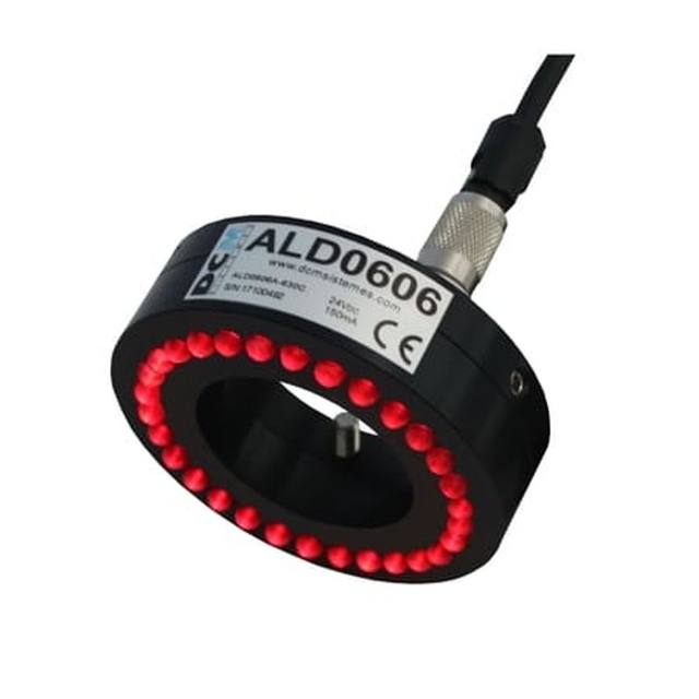
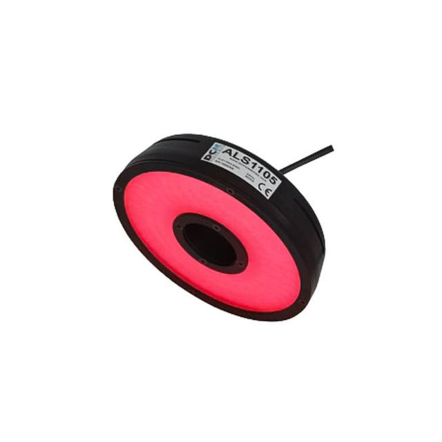
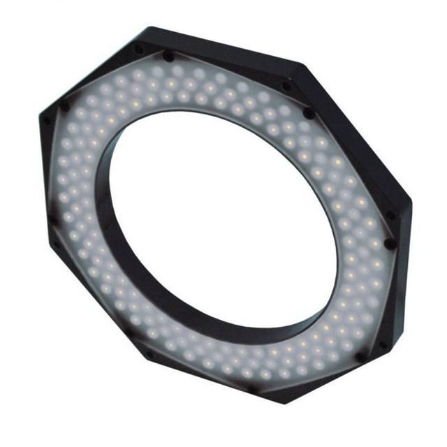
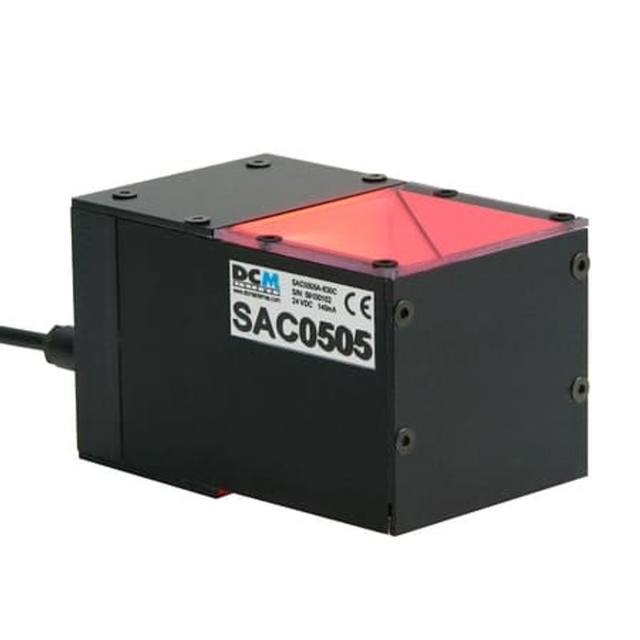
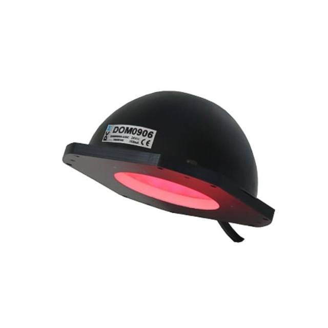
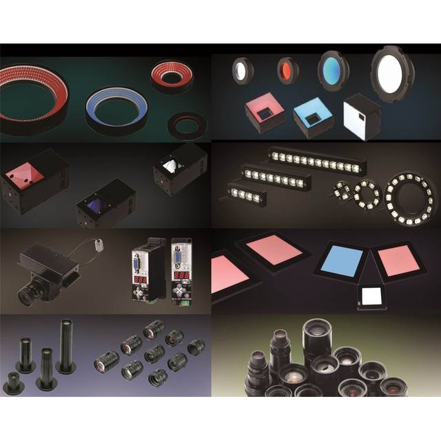
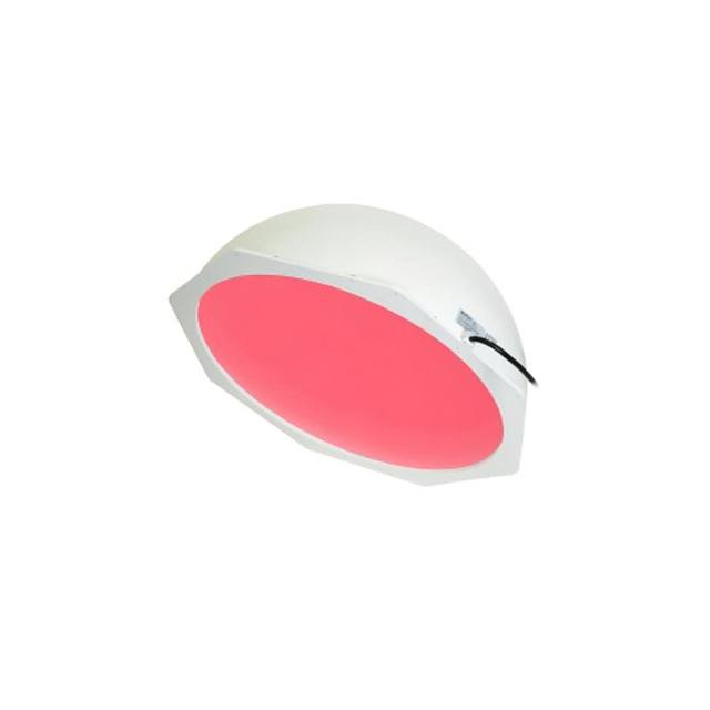
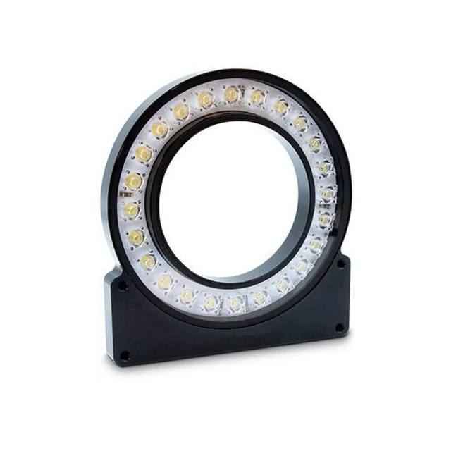
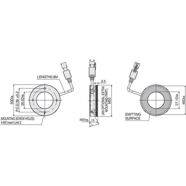
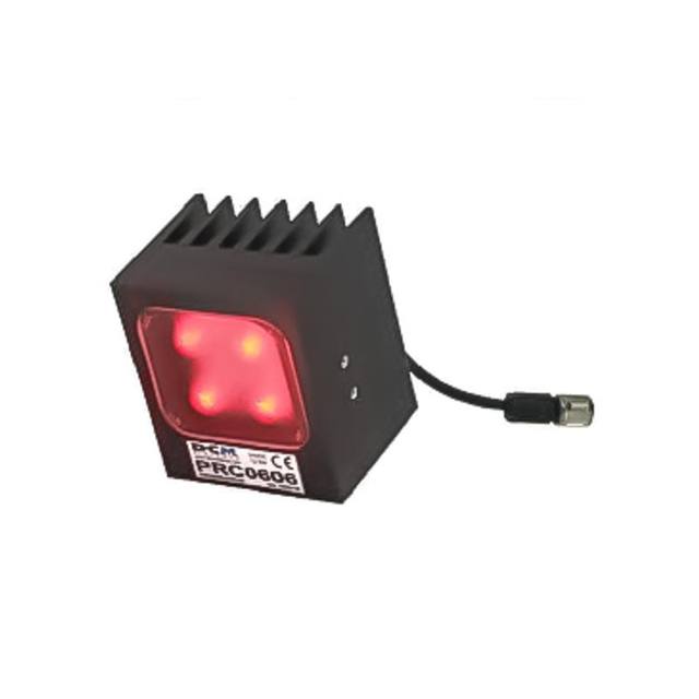
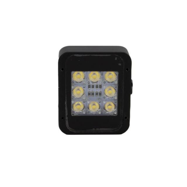
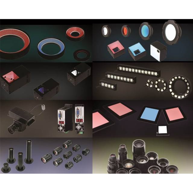
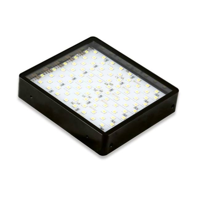
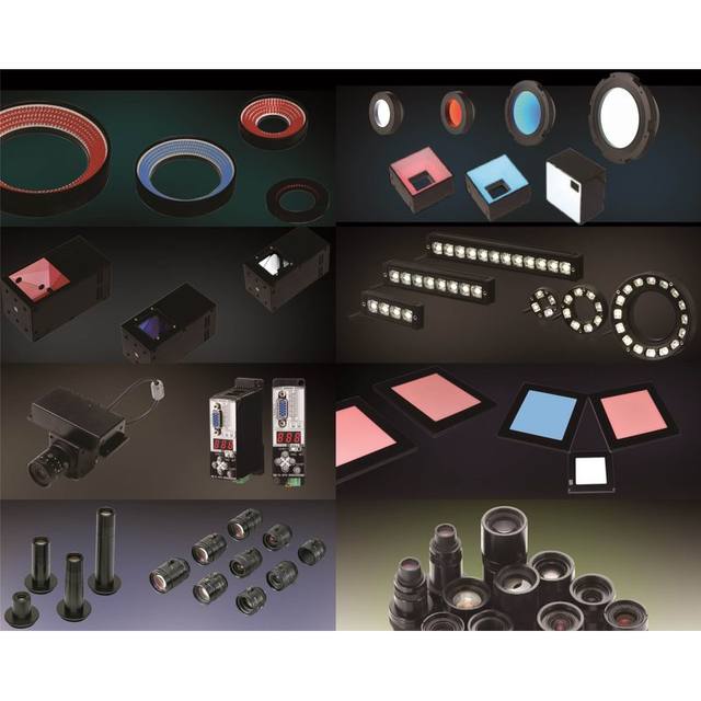
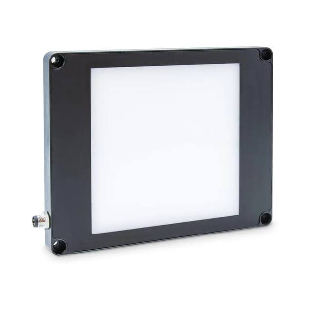
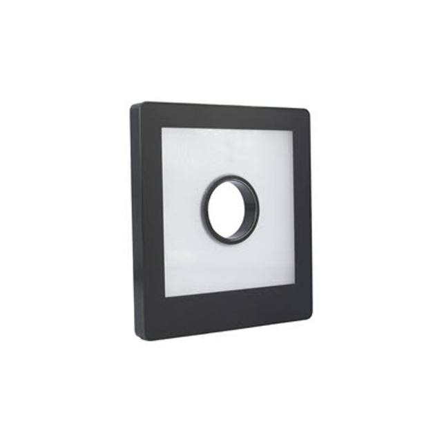
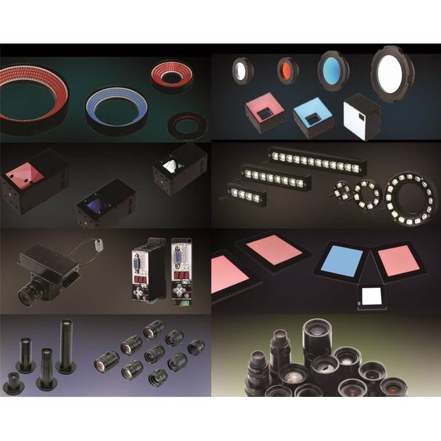
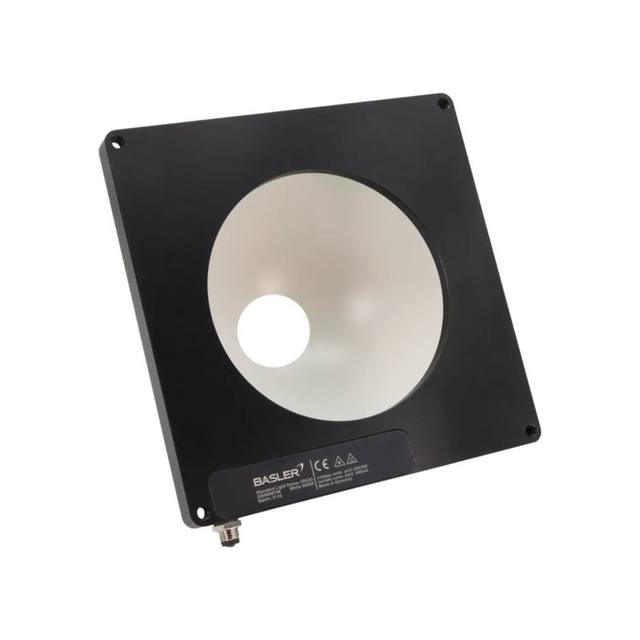
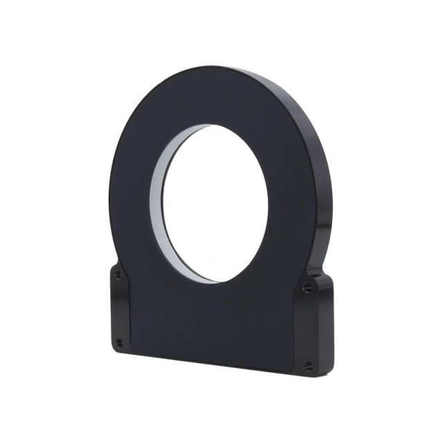
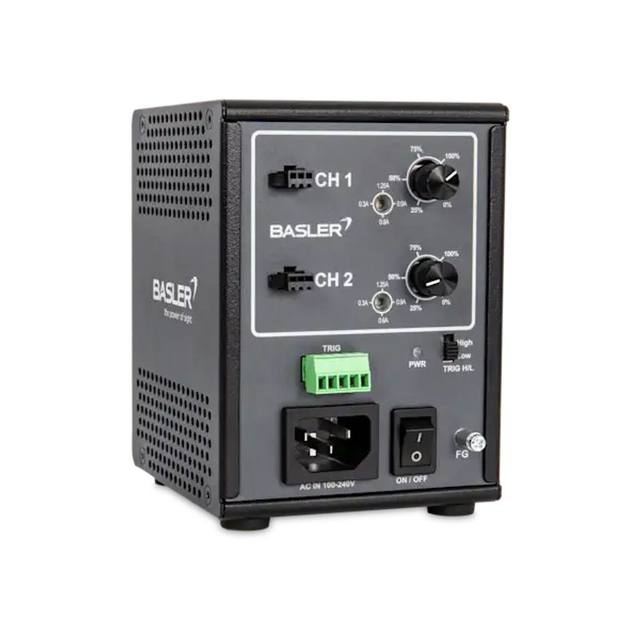
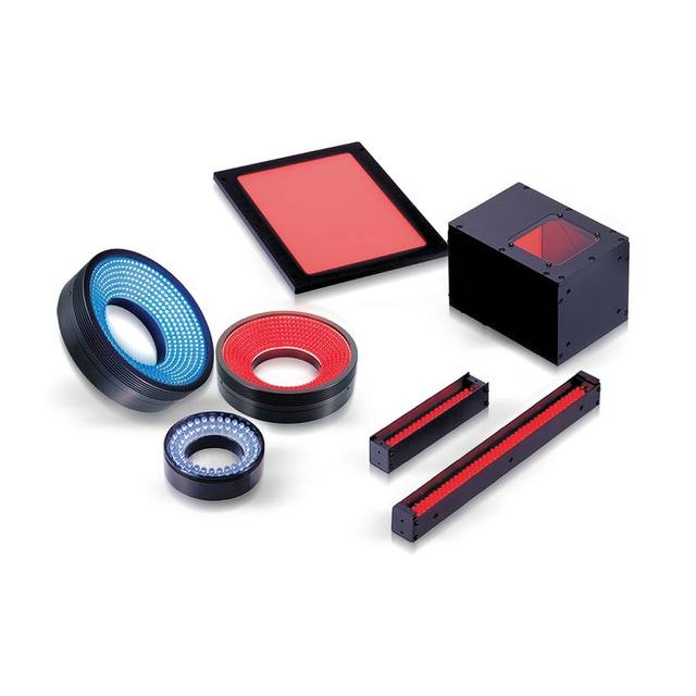
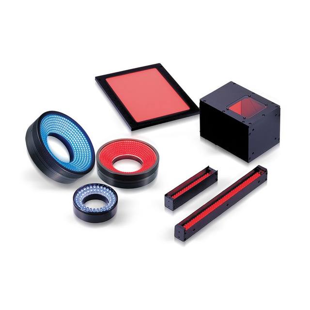
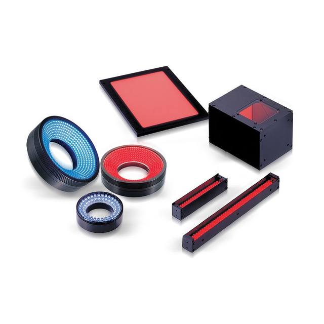
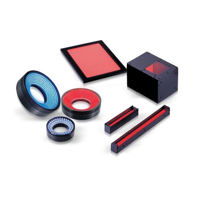
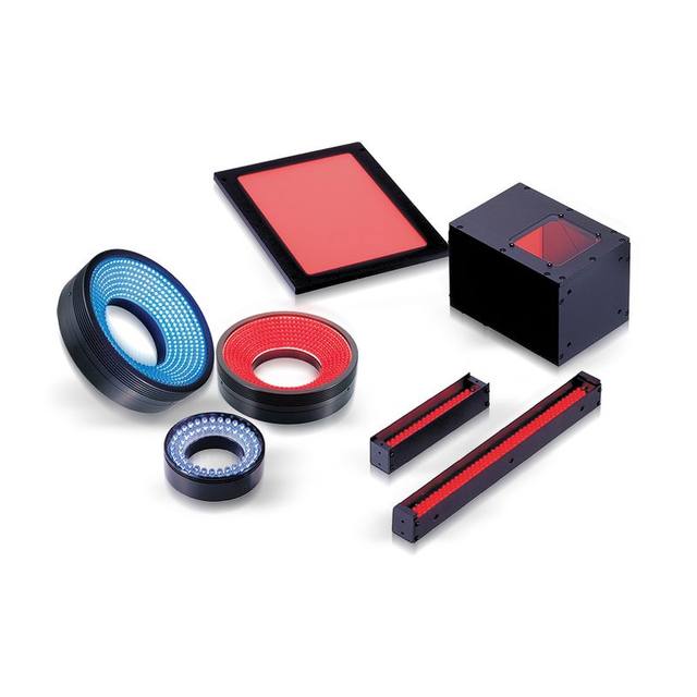
A few well-established techniques cover most surface and cosmetic work. Low-angle or dark-field lighting grazes the surface so that scratches, embossing, engraving and edge defects scatter light and appear bright against a dark background — ideal for topographic defects that a flat front light would wash out. Diffuse dome (cloudy-day) lighting eliminates glare on curved, shiny or specular parts and gives an even field that suppresses nuisance reflections, useful before an AI stage so the model does not learn the reflections. Coaxial / on-axis lighting flattens flat reflective surfaces such as metal, glass and printed labels. Backlighting throws edges and through-holes into sharp silhouette for shape and contour defects. DCM Sistemes supplies ring, bar, coaxial/axial, dome and dark-field families for exactly this range of techniques, and the catalog also carries lighting from Basler and Omron for camera-matched kits.
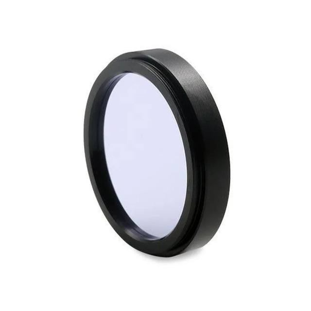
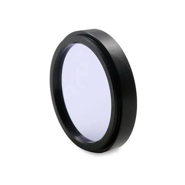
Two further points decide repeatability. First, wavelength and filtering: a monochromatic source (often red, or blue/UV to lift fine surface texture) paired with a matching bandpass filter on the lens rejects ambient light and stabilises contrast — the filter is part of the lighting design, not an afterthought. Second, control: strobing the light in sync with a moving part and driving it from a stable controller keeps brightness constant as lamps age. For an AI model, that stability is what keeps the training set valid in production.
- Dark-field / low-angle: scratches, embossing, engraving, edges and other topographic defects.
- Diffuse dome: glare-free imaging of curved, shiny and specular surfaces.
- Coaxial / on-axis: flat reflective surfaces — metal, glass, printed labels.
- Backlight: edge, contour and through-hole defects in silhouette.
- Add a bandpass filter matched to a monochromatic source to reject ambient light and lock down contrast.
Lens and filters: delivering the detail to the sensor
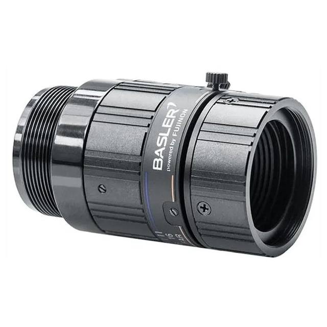
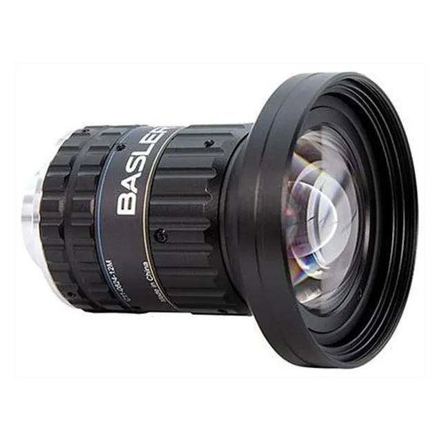
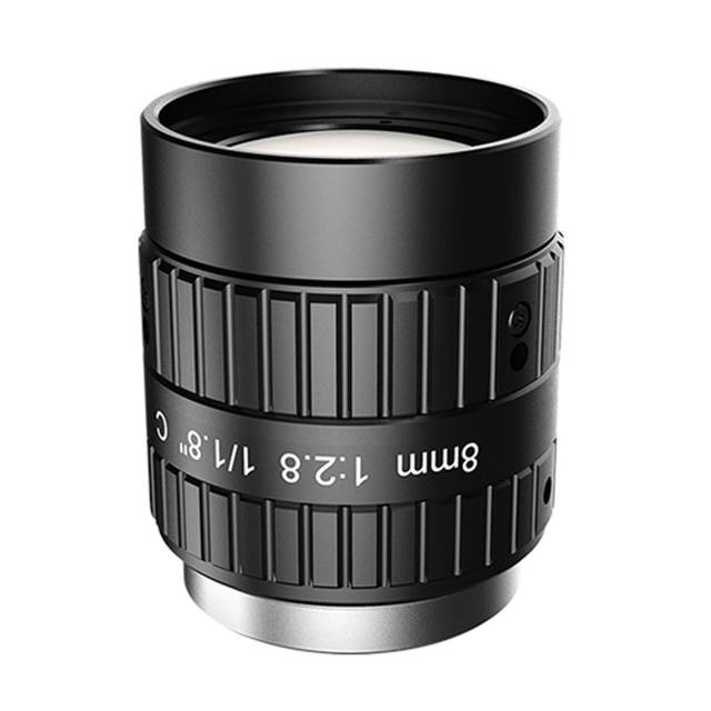
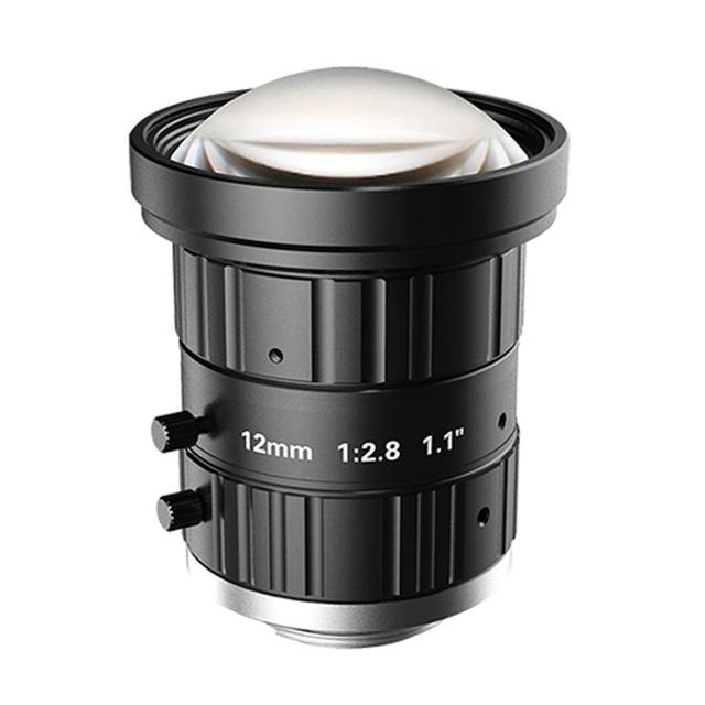
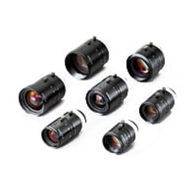
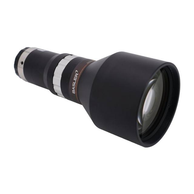
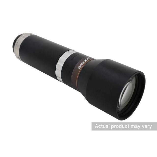
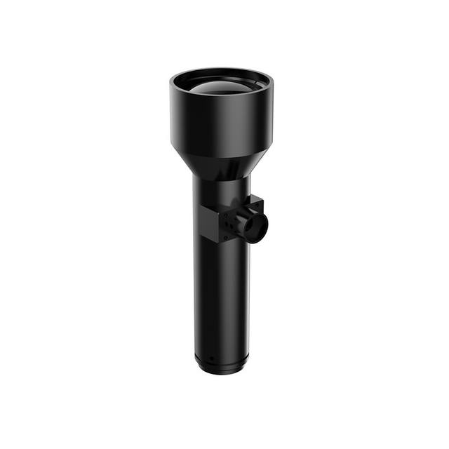
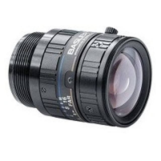
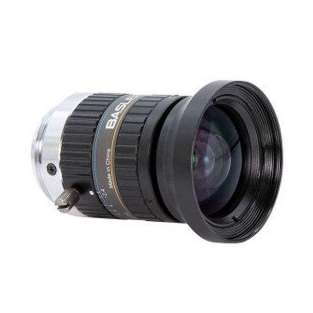
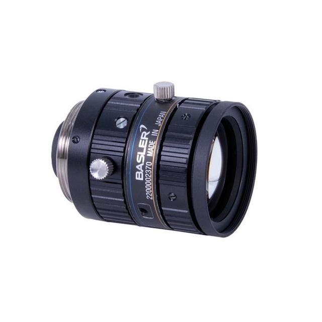
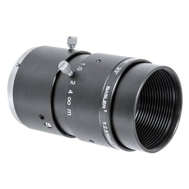
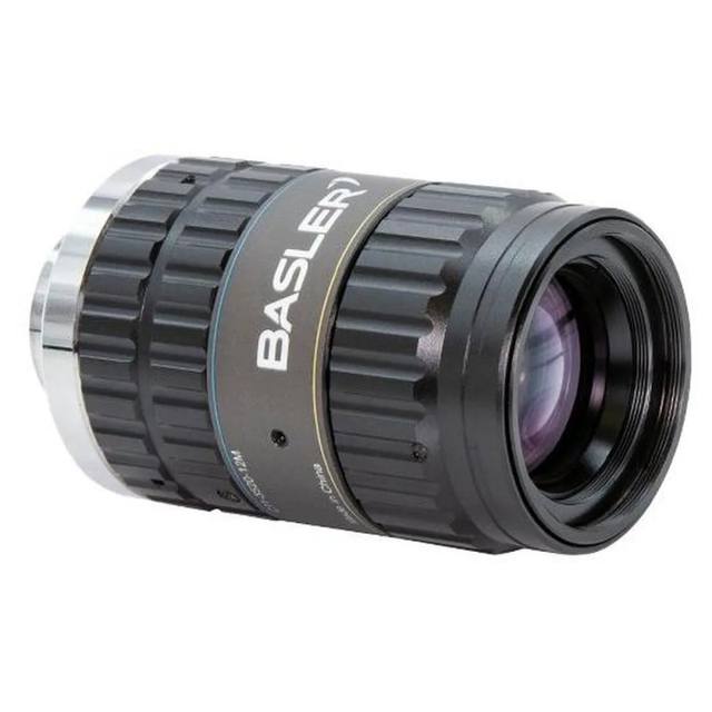
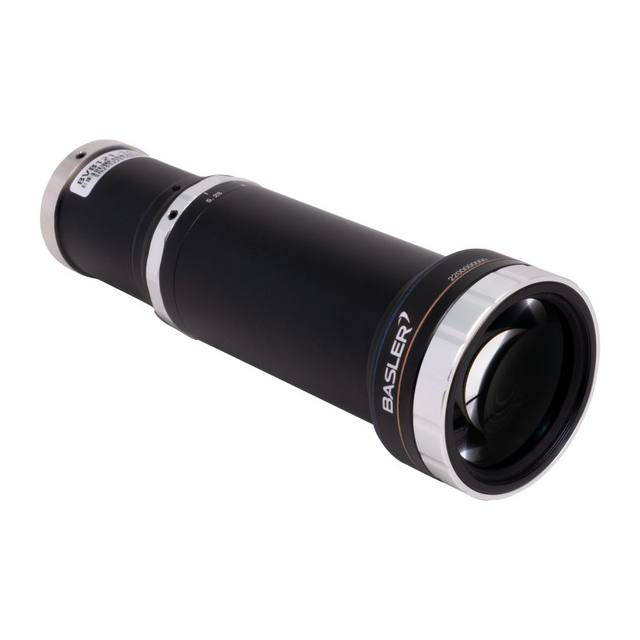
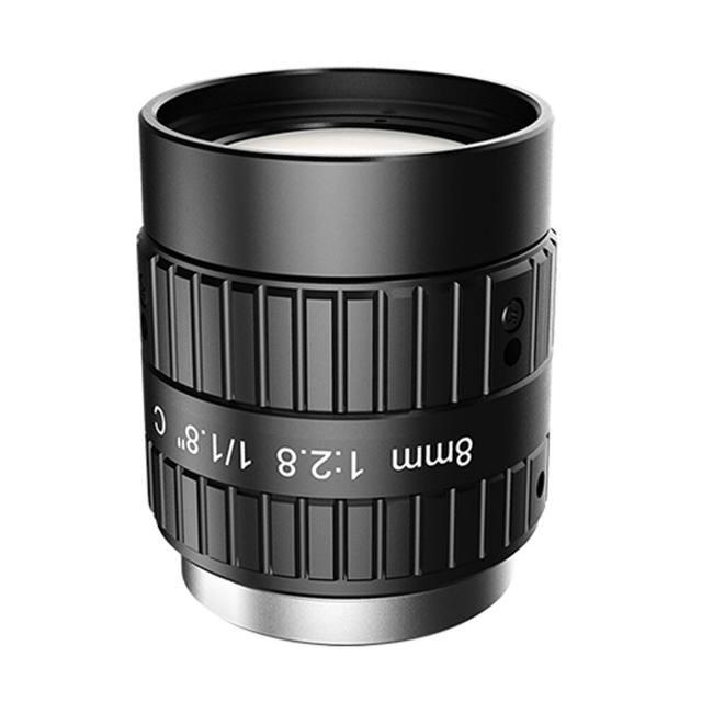
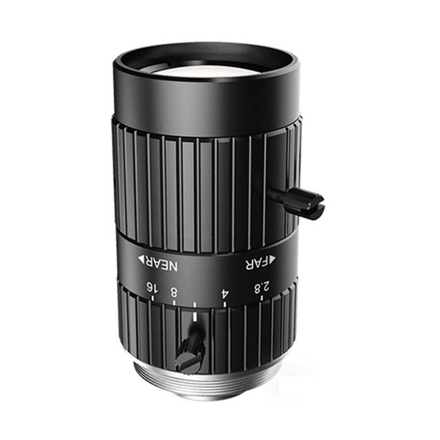
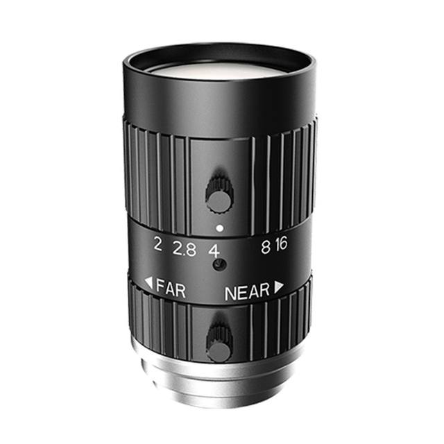
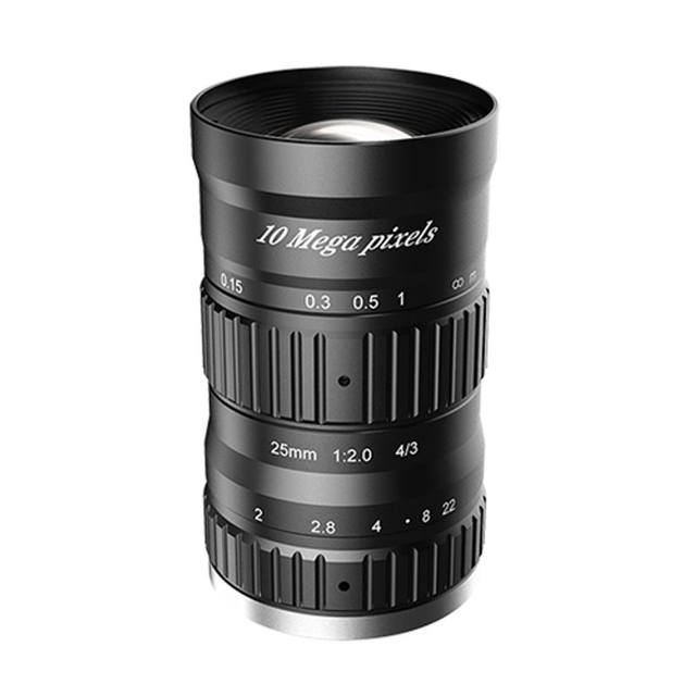
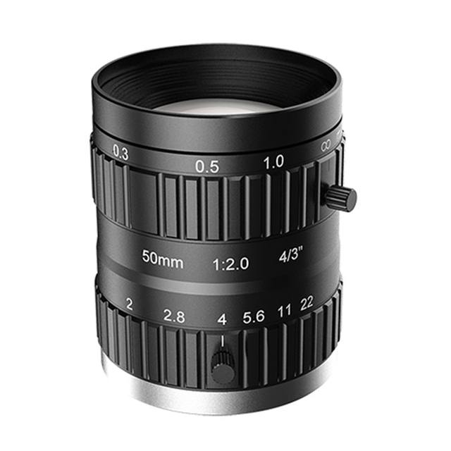
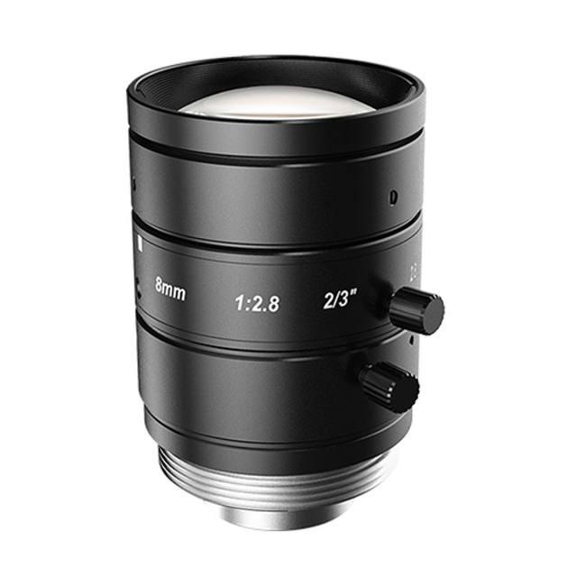
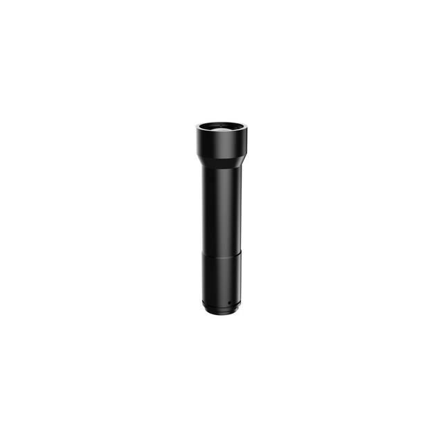
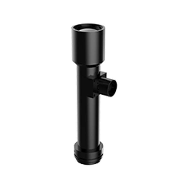
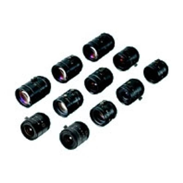
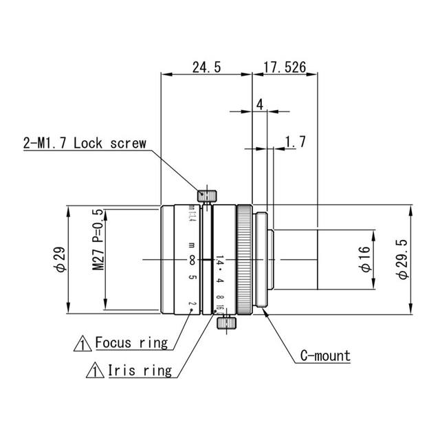
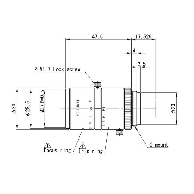
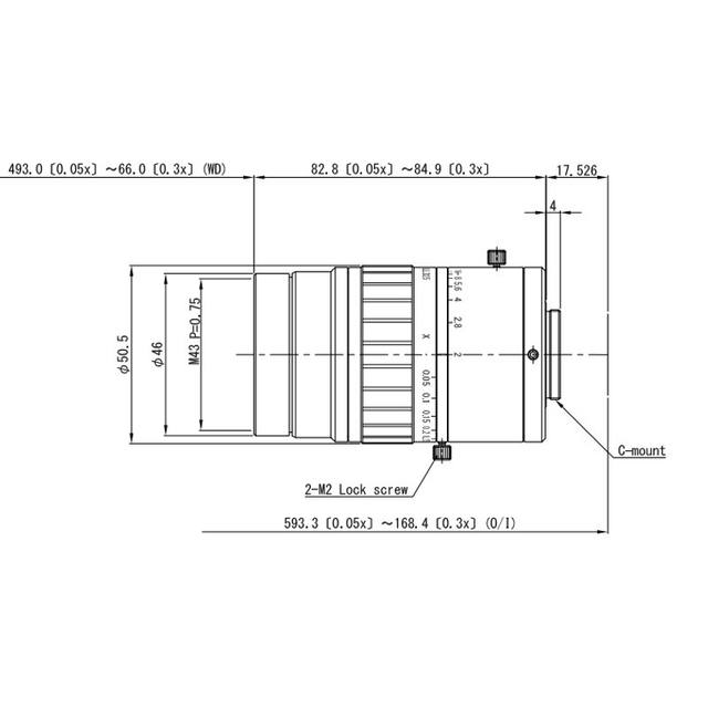
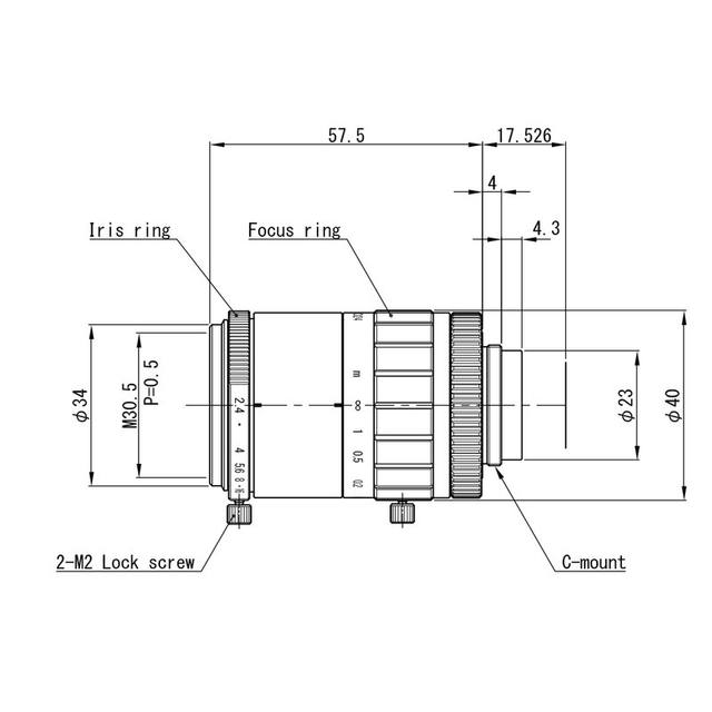
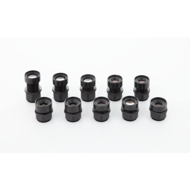
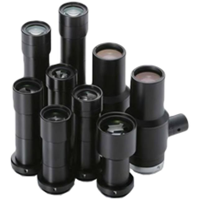
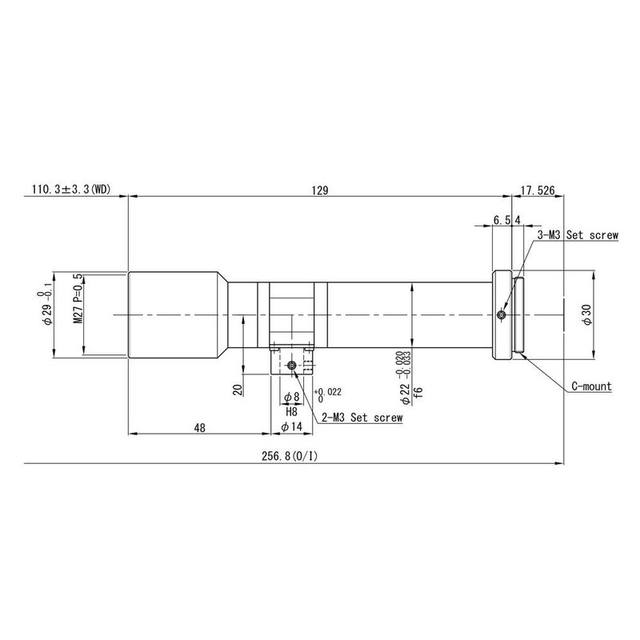
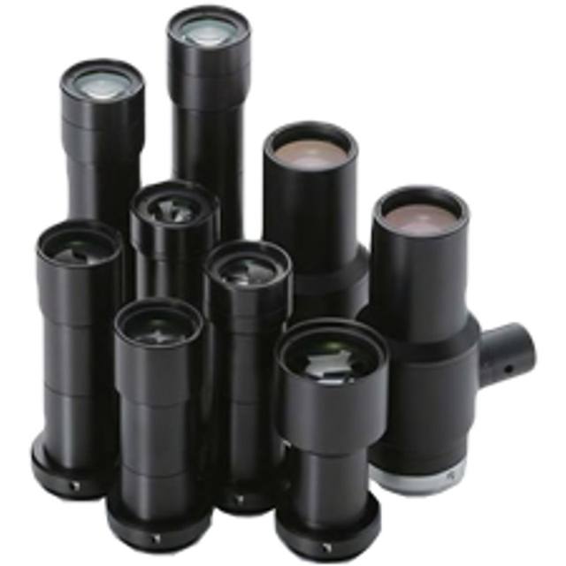
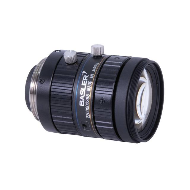
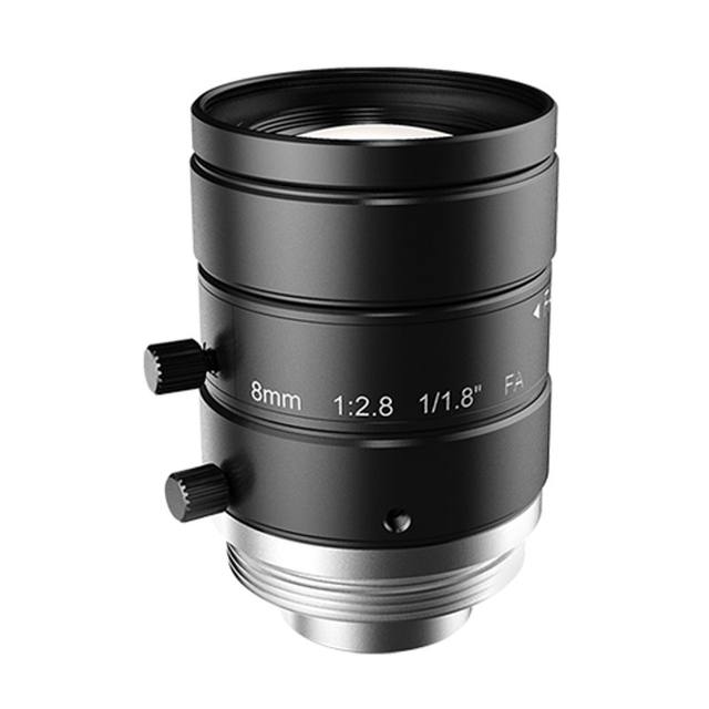
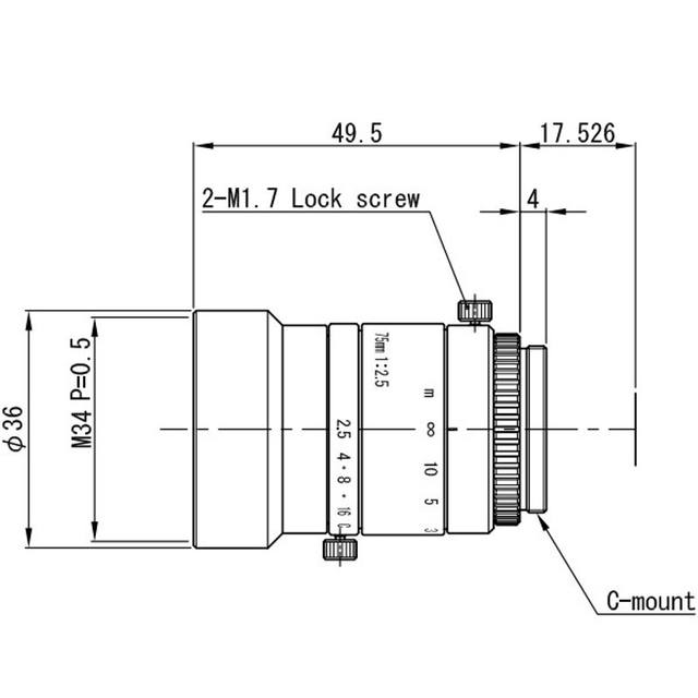
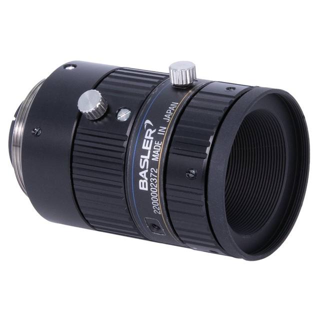
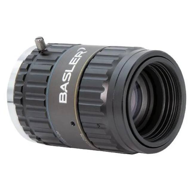
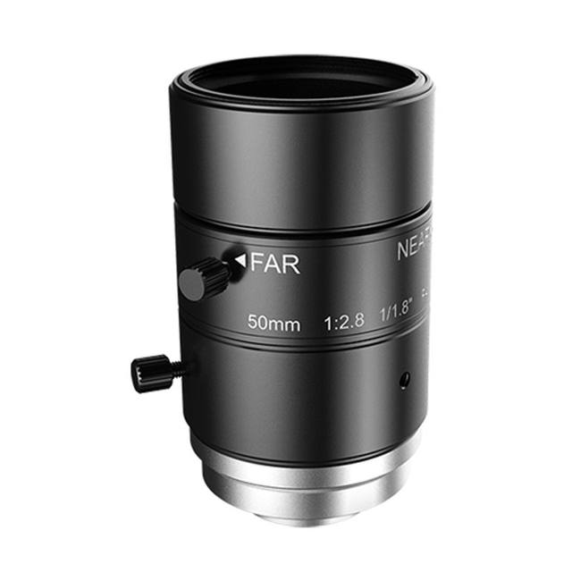
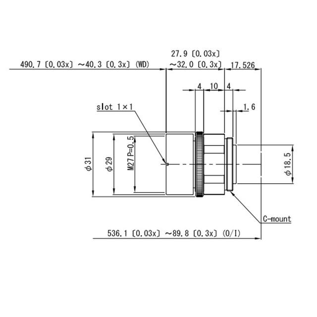
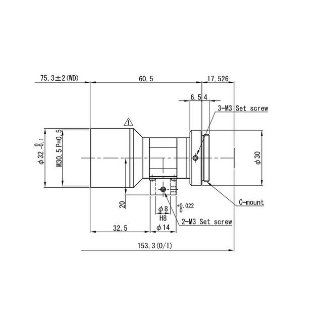
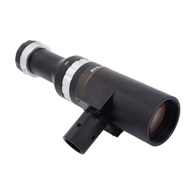
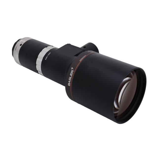
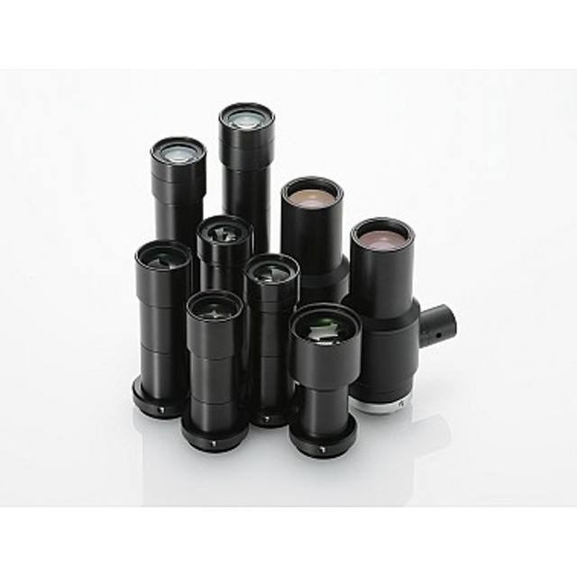
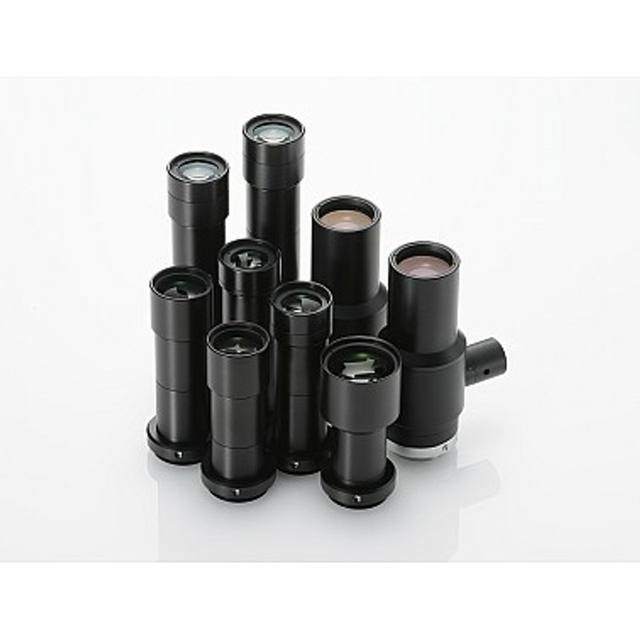
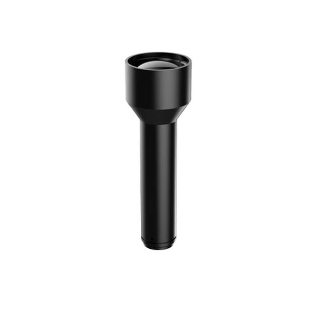
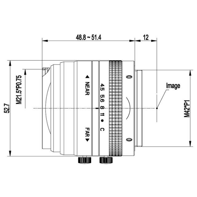
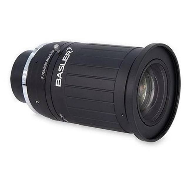
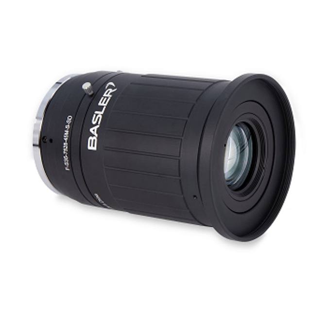
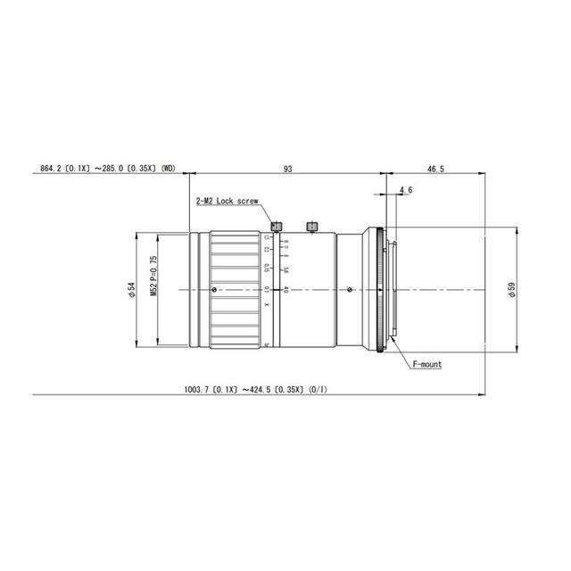
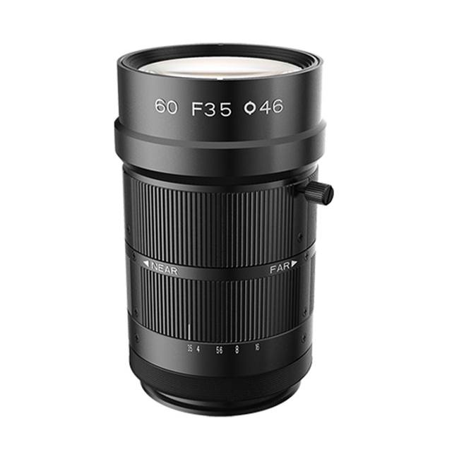
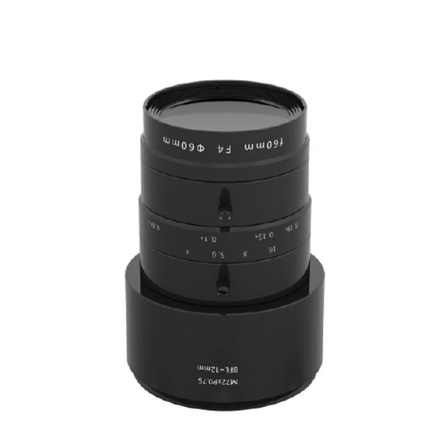
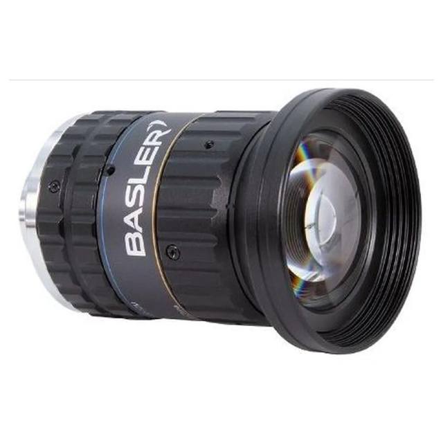
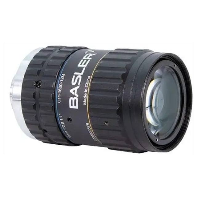
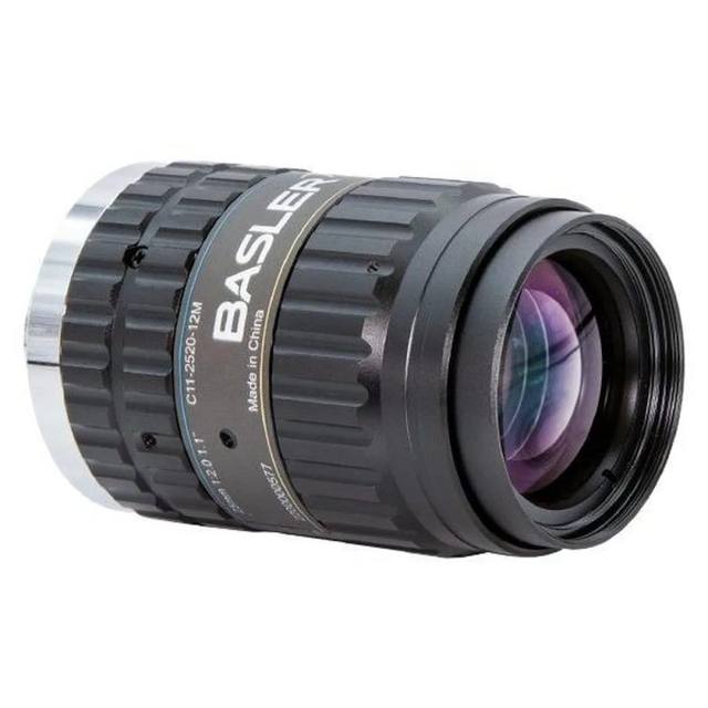
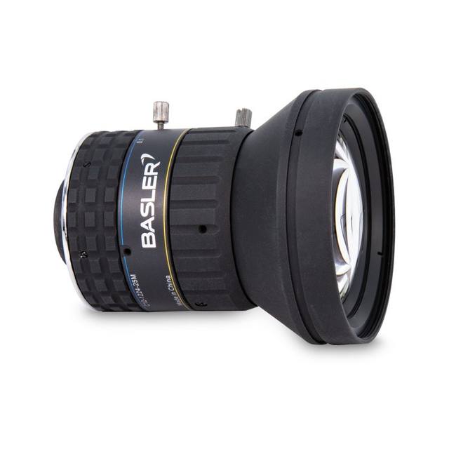
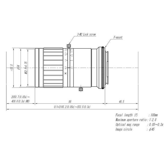
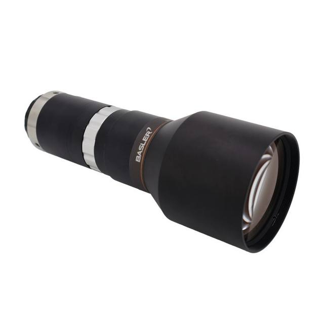
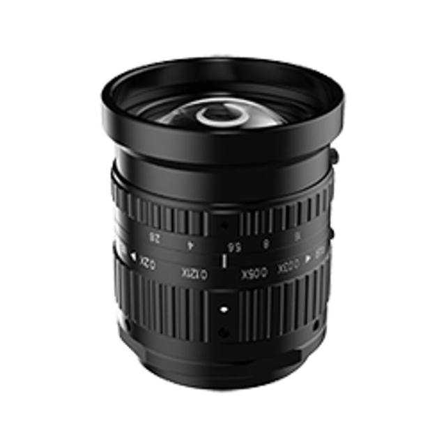
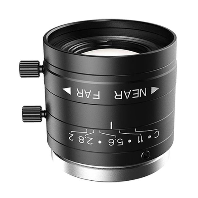
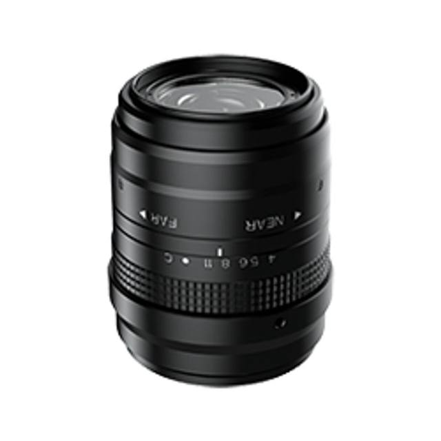
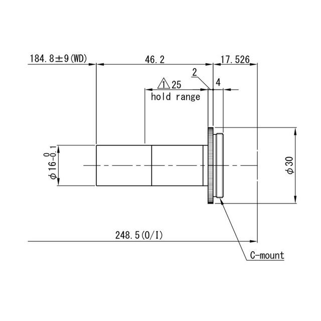
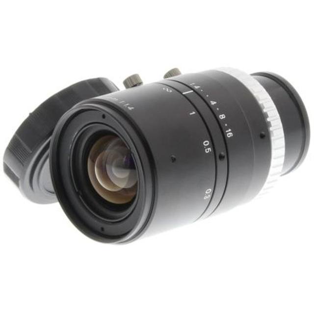
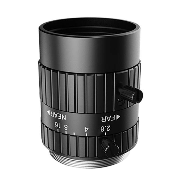
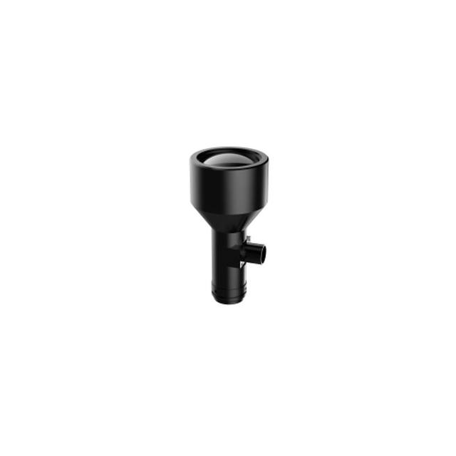
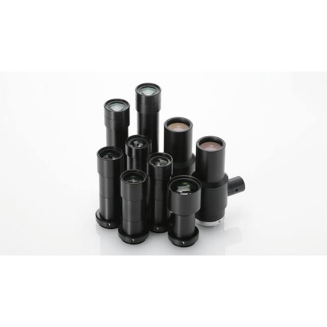
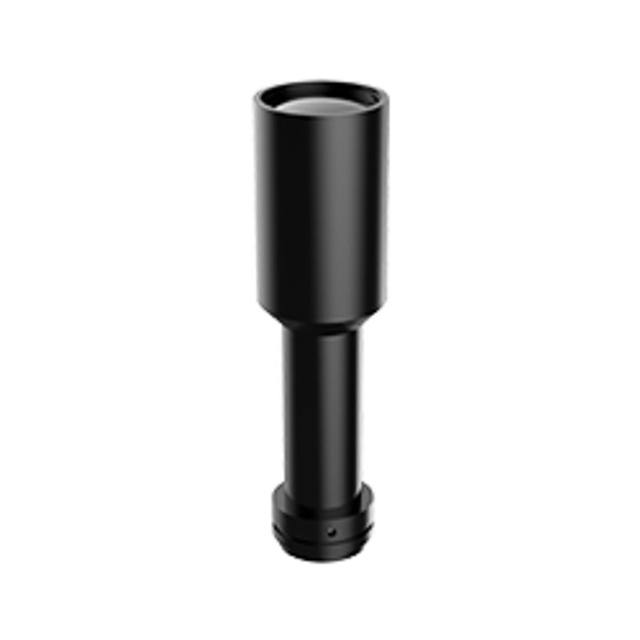
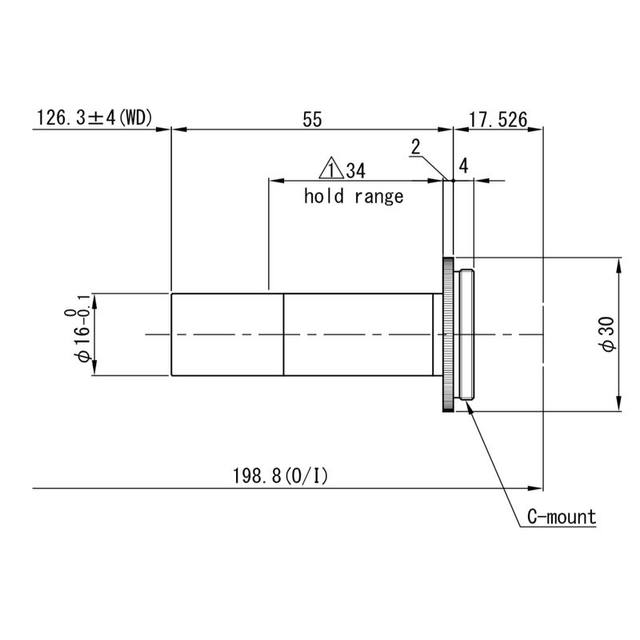
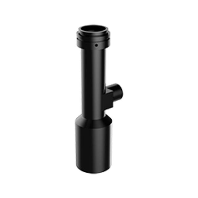
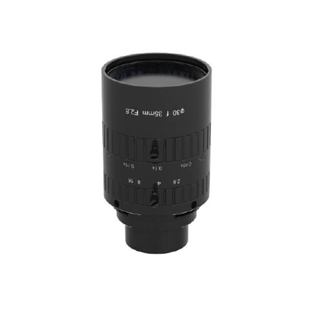
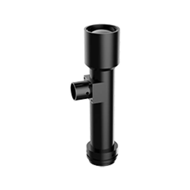
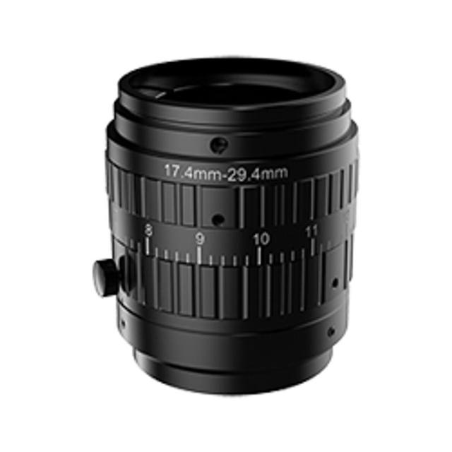
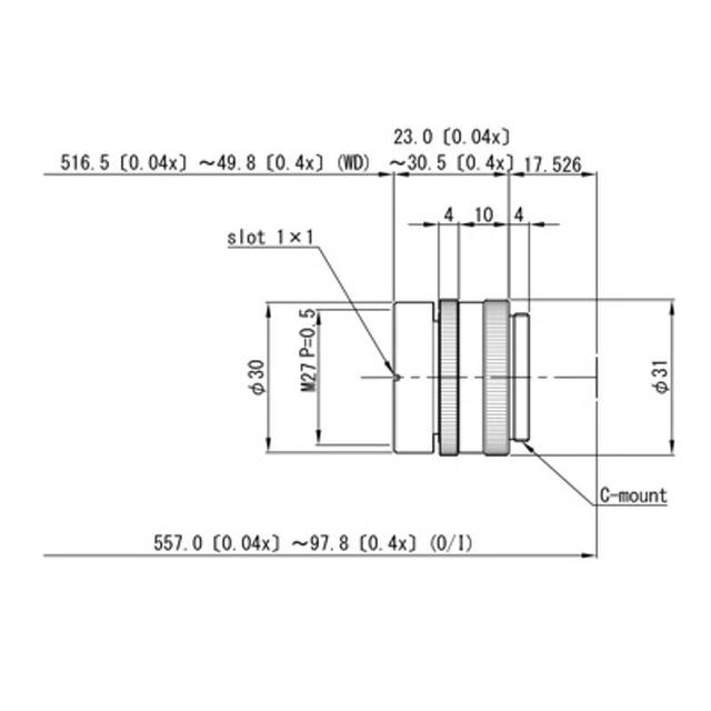
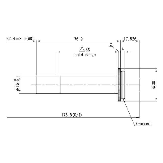
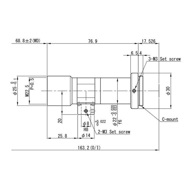
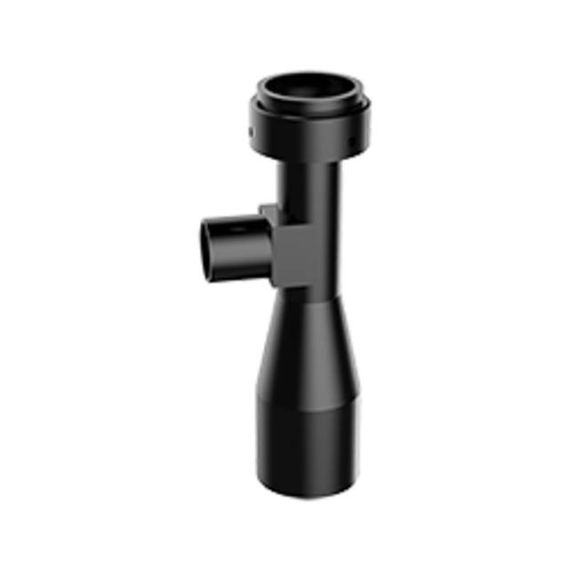
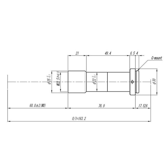
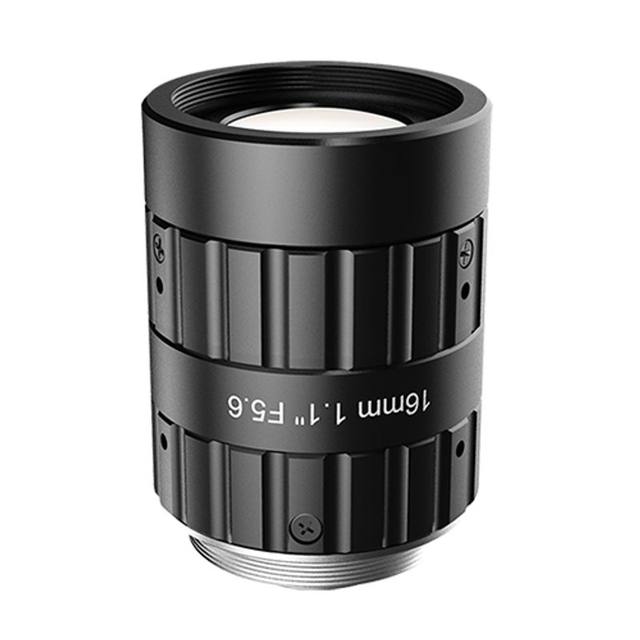
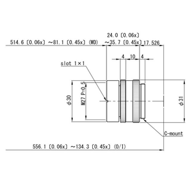
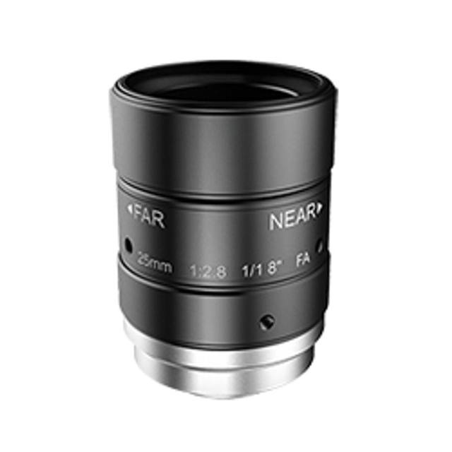
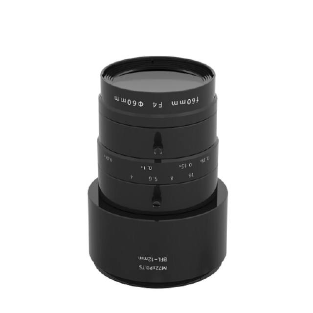
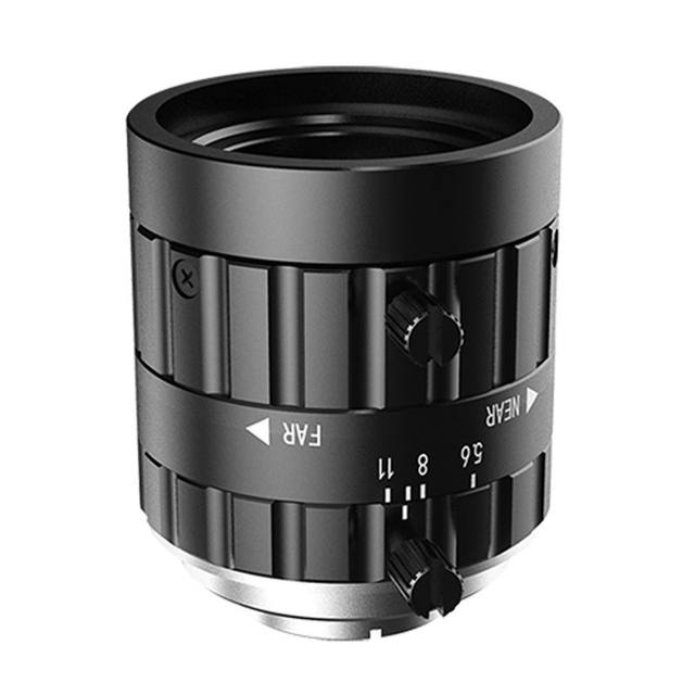
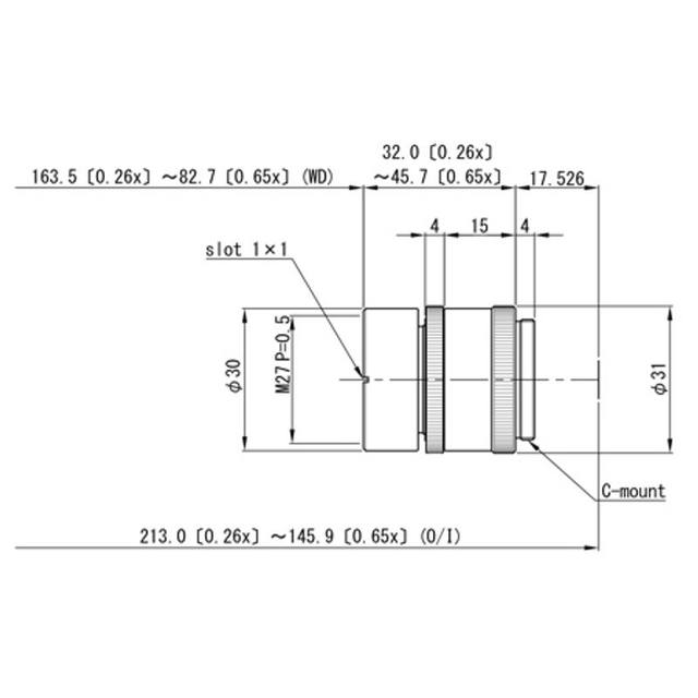
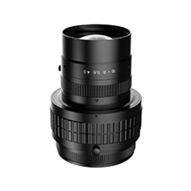
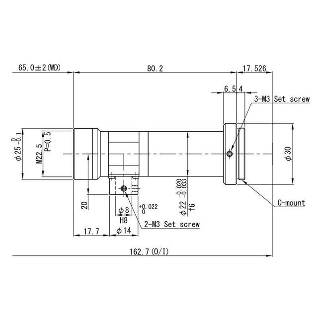
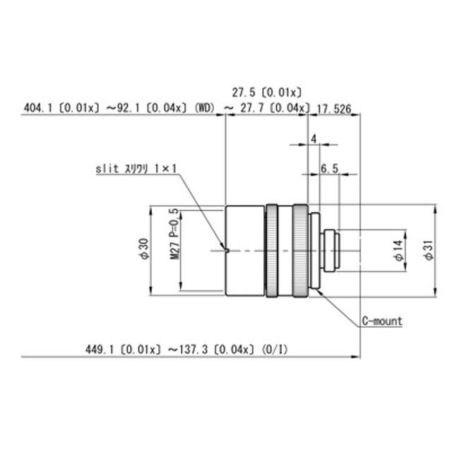
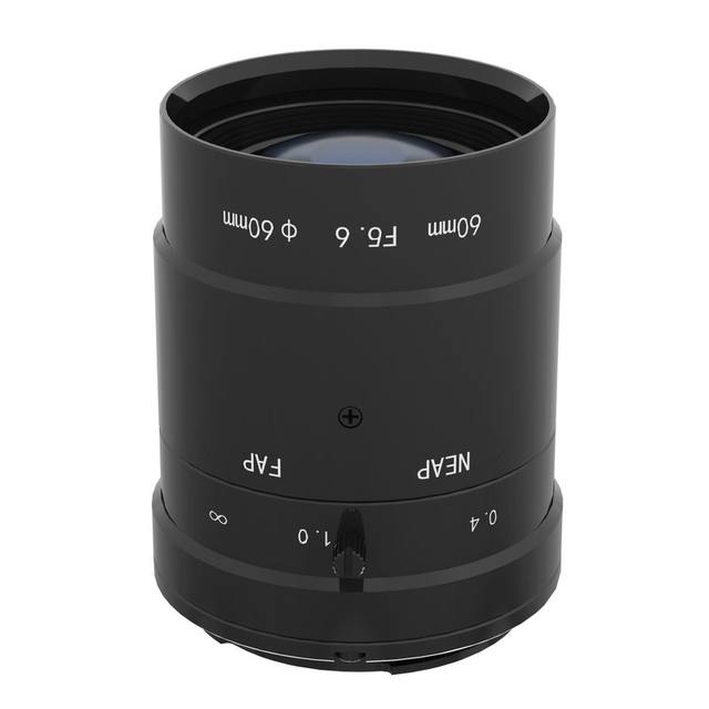
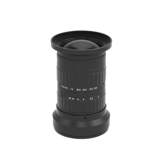
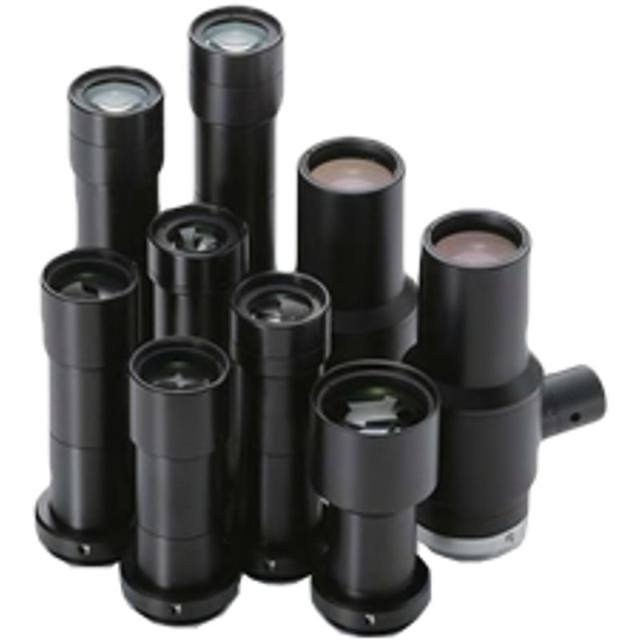
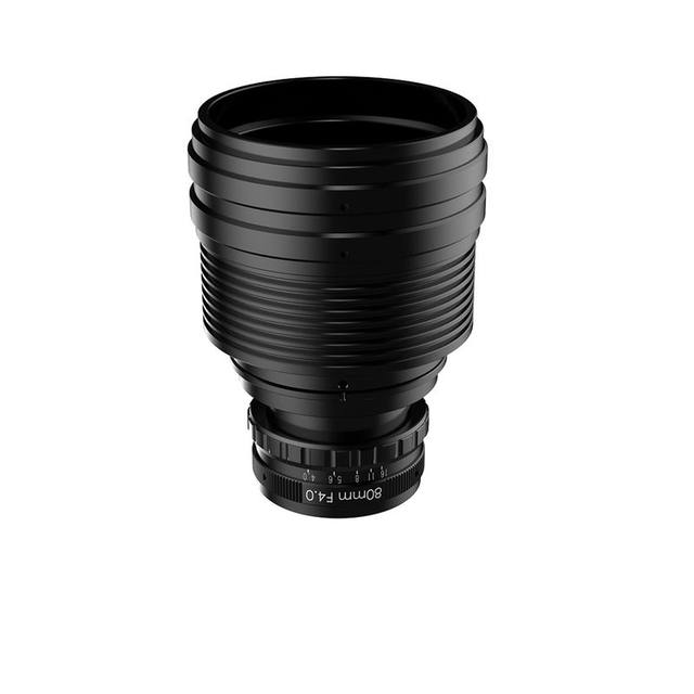
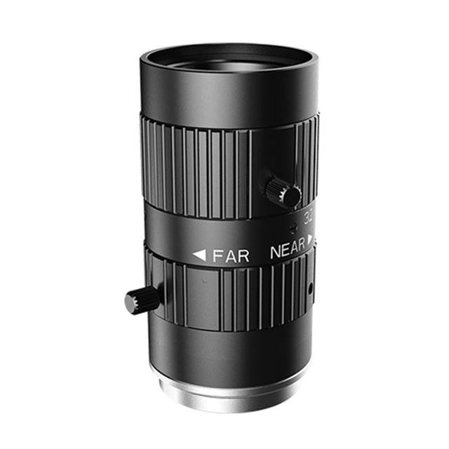
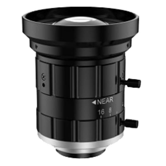
The lens forms the image the sensor samples; software cannot recover detail the optics never delivered. Size the focal length from your field of view and working distance, confirm the lens image circle covers the sensor diagonal, and — critically for high-resolution defect work — choose a lens whose resolving power (read from its MTF curves, not a megapixel headline) keeps up with the sensor's pixel pitch. Pairing an ordinary lens with a fine-pitch, high-resolution sensor quietly throws away the resolution you paid for, and the soft image that results gets wrongly blamed on the camera or the model.
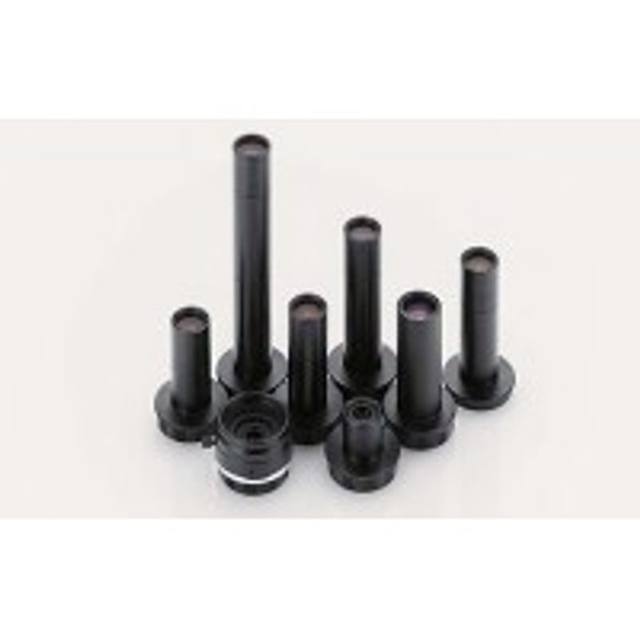
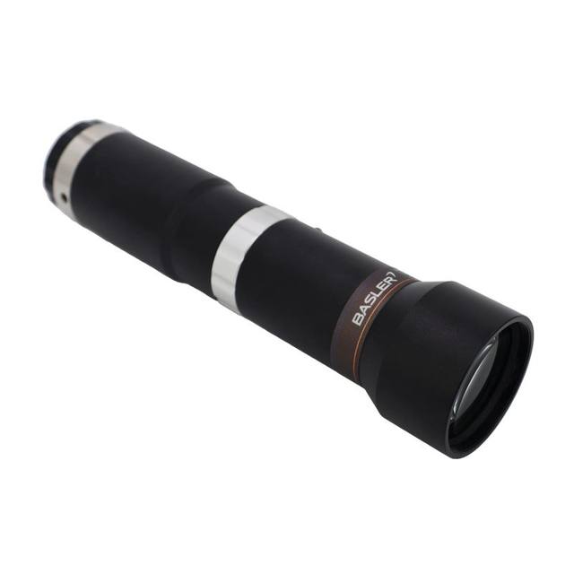
Aperture and depth of field are a balance with the lighting. Stopping down deepens depth of field and cleans up the corners, which matters when parts vary in height or sit at an angle, but it costs light — so good controlled lighting is what lets you work at the sharp aperture sweet spot rather than wide open. For pure defect detection a quality fixed-focal-length lens is usually right; reserve telecentric optics for cases where edge position must stay exact regardless of part height.
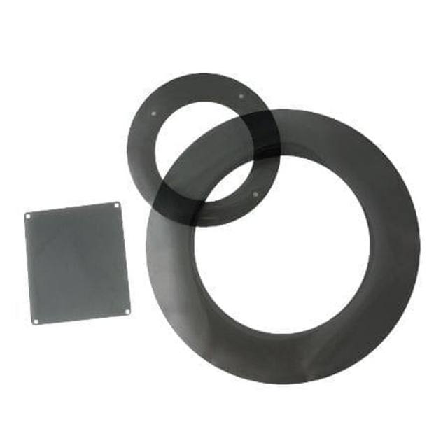
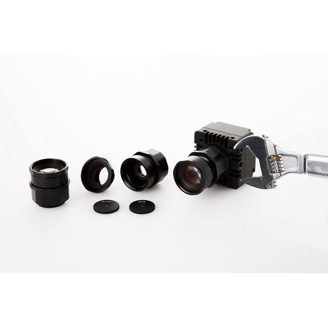
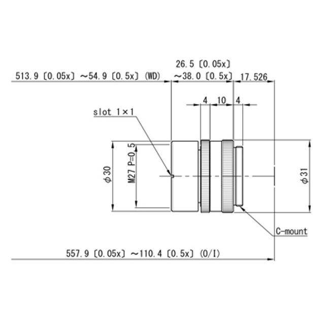
Treat the optical filter as part of the optical design. A bandpass filter matched to the illumination wavelength suppresses ambient light and stabilises contrast; a polariser cuts specular glare on shiny parts; UV or IR work needs glass corrected for that band. The catalog's lenses and filters span the C-mount and large-format optics and the filters these cameras need, so the whole chain — sensor, lens, filter, light — can be specified as one coherent system.
Where the AI runs, and proving it on your parts
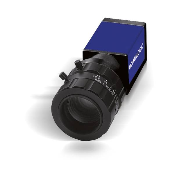
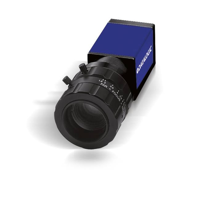
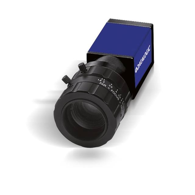
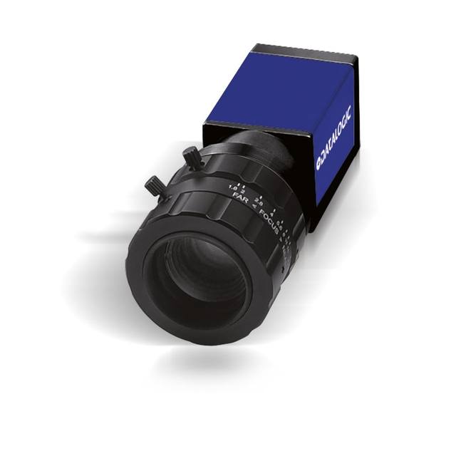
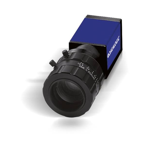
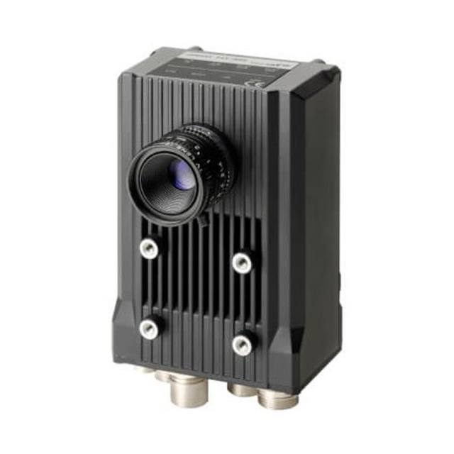
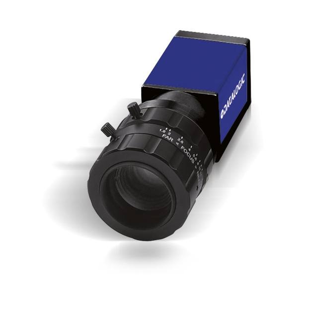
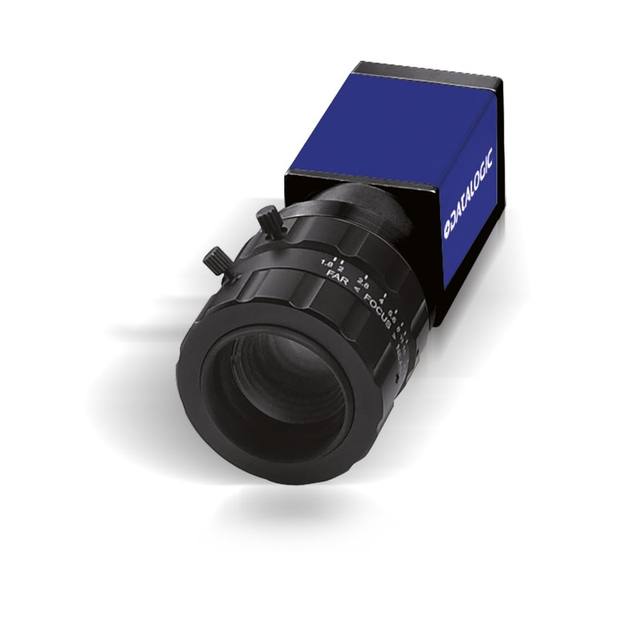
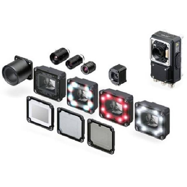
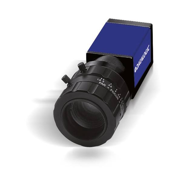
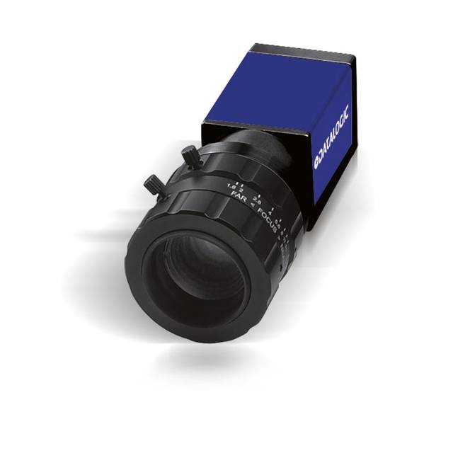
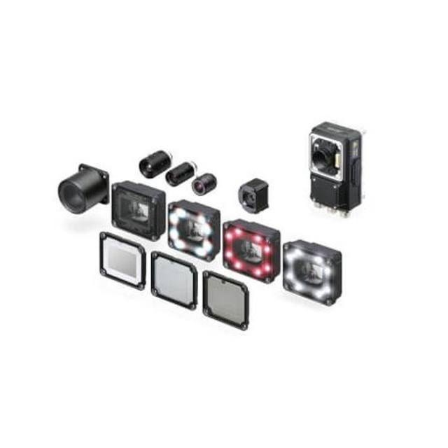
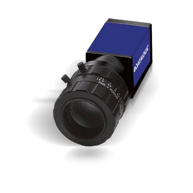
Where the deep-learning model executes is an architecture decision, not just a hardware one. A smart camera integrates sensor, optics, processing and often lighting into one rugged unit, and modern AI-capable smart cameras (for example the Omron FHV7 family, and Datalogic/Datasensing smart cameras) can run trained models at the edge. They suit single-view inspections, tight enclosures, lower part rates and applications where wiring and footprint matter more than raw compute. A PC-based system, by contrast, pairs industrial cameras with a workstation for far more processing headroom: larger models, multiple cameras fused across one part, high resolution and throughput, and free retraining as the defect catalogue evolves.
A pragmatic route is to prove feasibility on a PC-based setup with full-resolution images and a flexible training loop, then decide — once the defect classes and the required model are understood — whether the production deployment can be condensed onto a smart camera or needs to stay on a PC. Either way, the imaging hardware in front of the model is what determines whether the project succeeds, so the lowest-risk first step is an imaging feasibility check on real samples: capture representative good and bad parts under candidate lighting and confirm the defect shows up with stable, separable contrast.
Where the inspection genuinely needs AI — variable, low-contrast or hard-to-describe cosmetic defects, or text and characters that vary in print quality — the practical move is to send sample images so they can be evaluated with Rosepetal, the group's deep-learning visual-inspection software, to confirm the defect classes are learnable and to gauge expected performance. From there, AIS Vision can integrate the full system: camera, lens, filter and lighting selection, mechanical and ambient-light control, model training and the line integration that turns a working demo into a stable production inspection.
- Smart camera: compact, rugged, integrated edge AI; best for single-view, lower-rate, space-constrained installs.
- PC-based: maximum compute, multi-camera fusion, large or frequently retrained models, high resolution and throughput.
- Common path: prove the application PC-based, then condense onto a smart camera if the production case allows.
- Lowest-risk first step: an imaging feasibility check on real good and bad samples before committing hardware.