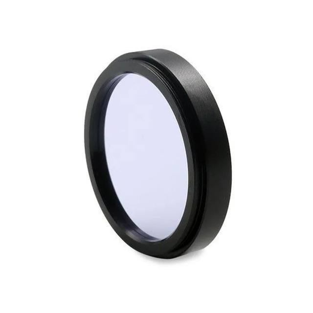
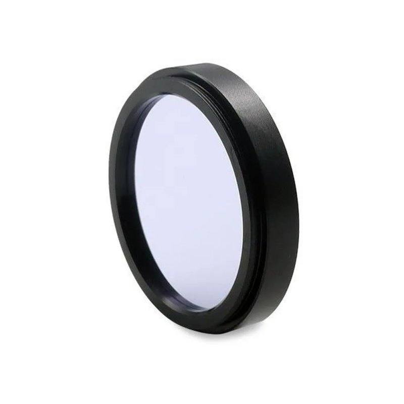
The Bi1300 is a short-wave infrared bandpass filter centered at 1300 nm with a 35 nm FWHM bandwidth, transmitting in the 1290–1310 nm useful range at ≥90% peak transmission. The 1 mm thick hardcoated optic uses M46 x 0.75 thread and meets 40/20 surface quality. It is engineered to match 1300 nm LED illumination and to enhance image quality for InGaAs cameras in life science, laser analysis, and industrial inspection tasks. Basler distributes this MidOpt-manufactured filter under order number 2200001554.
The Basler Bi1300 is a narrow-bandwidth short-wave infrared (SWIR) bandpass filter centered at 1300 nm with a 35 nm full-width at half-maximum (FWHM) passband, transmitting wavelengths in the 1290–1310 nm useful range at peak transmission of 90% or better. This 1 mm thick, hardcoated optic uses an M46 x 0.75 thread and meets 40/20 scratch-dig surface quality, making it a precision optical component suited for demanding inspection and life-science environments. Because the filter passes only a tightly bounded slice of SWIR energy, it eliminates broadband thermal background, ambient visible light, and out-of-band SWIR radiation that would otherwise reduce image contrast and introduce measurement error.
The 1300 nm center wavelength is specifically matched to 1300 nm LED illumination sources. When the illuminator and filter are paired, the camera sees only the reflected or transmitted energy at that exact wavelength, dramatically improving signal-to-noise ratio on materials that exhibit characteristic absorption or transmission features in this region — including silicon wafers, pharmaceutical tablet coatings, moisture-laden food products, and biological tissue. The narrow 35 nm passband is narrow enough to resolve spectral differences between similar materials yet wide enough to pass sufficient photon flux from a 1300 nm LED source without demanding impractical exposure times. Out-of-band rejection is a direct consequence of the bandpass coating: wavelengths outside the 1290–1310 nm window are attenuated, ensuring that stray room lighting and competing SWIR sources do not corrupt the image.
This filter is manufactured by MidOpt and distributed by Basler as order number 2200001554. It is engineered for use with InGaAs focal-plane-array cameras, which are the standard silicon-free detector technology sensitive in the 900–1700 nm SWIR band. The M46 x 0.75 thread is a common filter-ring size found on many C-mount and CS-mount SWIR lenses with 46 mm front barrel diameter. The 1 mm glass thickness introduces negligible focus shift at typical machine-vision working distances, so no back-focal-distance compensation is required when mounting the filter directly on the lens. The 40/20 surface quality specification means the filter introduces no measurable scatter or imaging degradation compared to the lens optics themselves.
Best for
InGaAs camera systems requiring isolation of 1300 nm illumination from broadband ambient light in indoor or semi-outdoor industrial environments
Pharmaceutical and food-and-beverage inspection tasks where moisture content, coating thickness, or compositional differences between materials show distinct absorption contrast at 1300 nm
Semiconductor and electronics inspection applications — such as through-silicon imaging of wafer bond lines or solder joints — where silicon is transparent at 1300 nm but must be imaged without interference from visible-band stray light
Life-science and medical-device inspection setups using 1300 nm LED illumination that need a matched cleanup filter to eliminate broadband background
Surface and defect inspection lines with monochromatic 1300 nm LED ring or dome lighting where maximizing contrast between surface features and background requires tight spectral control
Selection notes
Verify your lens has an M46 x 0.75 front thread before ordering. This is a 46 mm filter ring with 0.75 mm pitch — confirm against your lens specification sheet, as nearby sizes (M43, M49, M52) will not engage the thread correctly.
Match the illumination source center wavelength to 1300 nm. The 35 nm FWHM passband is forgiving of typical LED spectral spread, but a source centered at 1250 nm or 1350 nm will pass significantly reduced flux through the filter, requiring longer exposure times or higher illumination power.
This filter is intended for InGaAs or other SWIR-sensitive detectors. Silicon-based CMOS and CCD sensors have essentially no response above ~1100 nm, so the Bi1300 provides no imaging benefit on standard visible-band or near-IR cameras.
For applications where multiple SWIR wavelengths need to be compared — for example, multi-spectral moisture mapping — a single Bi1300 provides the 1300 nm channel only. A separate filter centered at a contrasting wavelength (e.g., 1100 nm or 1550 nm) would be needed for ratiometric or dual-band analysis.
The 40/20 scratch-dig surface quality and hardcoating make the Bi1300 suitable for cleanroom and laboratory environments, but handle with care: optical coatings on interference filters are more sensitive to cleaning abrasion than bare glass. Use dry nitrogen or gentle lens tissue with appropriate optical solvent.
Specifications: General
Brand
Basler
Specifications: Optical
Filter type
Bandpass
Filter wavelength
1300 nm CWL, 35 nm FWHM
Specifications: Mechanical
Thread / filter size
M46 x 0.75
Applications this camera is commonly selected for. Open one to see the full recommended hardware and approach.
Get a first image quickly with the pylon Viewer, then move into the pylon SDK for your application. These cameras are GenICam/GenTL-compliant, so any compliant vision software can drive them as well.
Download and install the pylon Camera Software Suite for your OS from Basler. This provides the pylon Viewer, the GenTL transport-layer producers and the pylon SDK (C/C++/.NET/Python). On Windows the installer adds the needed drivers; on Linux follow the included setup notes for USB and network permissions.
2. Connect the camera and check the link
Cable the camera to its matching interface: GigE Vision to a GigE port (use a quality cable and, ideally, a dedicated NIC with jumbo frames enabled), USB3 Vision to a USB 3.x port with the supplied cable, or CoaXPress to the frame grabber. Provide power where required (PoE, USB bus power, or PoCXP). Open the pylon Viewer and confirm the camera appears in the device list; for GigE, make sure the camera and NIC are on the same subnet.
3. Grab a first image and set exposure, gain and pixel format
Select the camera in the pylon Viewer and start a continuous grab. Adjust exposure time and gain until the image is well exposed (avoid clipped highlights), set the pixel format (e.g. Mono8 or a Bayer/RGB format), and focus the lens. Use a test pattern if the lens or scene is not ready yet.
4. Configure triggering and acquisition
Decide between free-run and triggered acquisition. For synchronized capture, set the trigger source (software or a hardware line on the I/O connector), trigger mode and any debounce or exposure mode, then verify timing. Note the parameter names you change in the Viewer feature tree, as you will reuse them in code.
5. Move to the SDK or a GenICam-compliant library
Recreate your settings in code with the pylon SDK (C, C++, .NET or Python) to open the device, apply the same features and pull frames into your pipeline; pylon vTools and pylon AI can add processing blocks. Because the cameras are GenICam/GenTL standard, third-party vision libraries work too. Once the image stream is stable, you can route frames to a deep-learning inspection such as Rosepetal for automated defect detection.
Frequently asked questions
InGaAs detectors are sensitive from roughly 900 nm to 1700 nm, meaning they respond to the full SWIR band including sunlight and broadband halogen sources that emit significant energy across that range. Without a bandpass filter, ambient SWIR radiation from these sources raises the background signal and reduces contrast between the illuminated feature and the background. The Bi1300's 35 nm passband admits only the 1290–1310 nm illumination band, rejecting the majority of broadband background energy and maximizing the signal-to-background ratio.
The Bi1300 uses an M46 x 0.75 thread — 46 mm diameter, 0.75 mm pitch. Check the front accessory thread specification in your lens datasheet. Common machine-vision lens thread sizes near 46 mm include M43, M46, M49, and M52; only M46 x 0.75 is compatible. If your lens has a different thread, step-up or step-down adapter rings are available from optical accessory suppliers, though this slightly increases the filter-to-lens distance and may vignette at large apertures.
A 1 mm glass plate introduces a focus shift of approximately 1 mm divided by the refractive index of the glass (typically ~1.5), giving a forward shift of roughly 0.33 mm. For most machine-vision lenses operating at working distances of 100 mm or more, this shift is within the depth of field and requires no compensation. In telecentric or macro lenses operating at very short working distances or very small f-numbers, you may observe a slight defocus and should refocus after mounting the filter.
No. Silicon CMOS and CCD sensors lose sensitivity rapidly above about 1000 nm and have essentially zero response at 1300 nm. The Bi1300 is designed exclusively for SWIR-sensitive detectors such as InGaAs focal-plane arrays. For silicon-based near-IR work in the 700–1000 nm range, a different bandpass filter centered in that window is needed.
Mount the Bi1300 directly onto the front thread of the lens before or after focusing — it does not affect the mechanical focus ring. Configure the illumination controller for the 1300 nm LED ring or dome at the desired intensity. With the filter in place, the camera image will contain only reflected energy from the 1290–1310 nm band, making the resulting grayscale image a direct proxy for surface or subsurface reflectance at that wavelength. This setup is the recommended configuration for pharmaceutical coating inspection, moisture-sensitive food product lines, and electronics surface inspection.