Scratches, dents, embossing, orange-peel, micro-pitting and tool marks share an awkward property: they are mostly invisible under the kind of even, bright illumination that suits print and assembly checks. The defect is a change in surface relief or local reflectance of a few microns to a fraction of a millimetre, and on a flat, specular or semi-glossy part it simply blends into the background until the light hits it at the right angle.
Solving surface inspection is therefore less about resolution alone and more about controlling the geometry of light and the way the part is presented to the sensor. Get the illumination angle and the camera architecture right and a defect that was statistically undetectable becomes a high-contrast feature any threshold or model can catch. This page frames the optical and acquisition decisions that make surface inspection robust, and explains why line scan cameras, dark-field lighting and high-speed imaging are the hardware that consistently delivers.
Why surface defects are hard to image
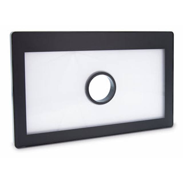
The core difficulty is contrast. A scratch is not a different colour from the material around it; it is a region where the surface normal has been disturbed, so it scatters or redirects light differently from the intact surface. Under diffuse, on-axis (bright-field) light, both the defect and the surface return light to the camera, the difference between them is small, and the resulting grey-level separation is too low to threshold reliably. The defect is physically present but radiometrically buried.
Specular and textured materials make this worse. Machined metal, coated panels, plastic mouldings, glass and brushed finishes produce hot-spots, glare and a noisy reflectance pattern that swamps the subtle signal of a real defect. Curvature compounds the problem: on a cylindrical or formed part, the angle between the surface and a fixed light source changes across the field of view, so an inspection that works at the centre fails at the edges. Embossing and debossing add a further twist, because these are deliberate relief features that must be read or verified rather than rejected, which again depends entirely on directional shadowing to become legible.
The practical consequence is that surface inspection is won or lost at the optics stage, before any image processing. The recommended approach is to engineer the lighting geometry so the defect produces a strong, repeatable signal, then choose a camera architecture that can capture that signal across the full part at production speed.
Dark-field and grazing light to reveal relief
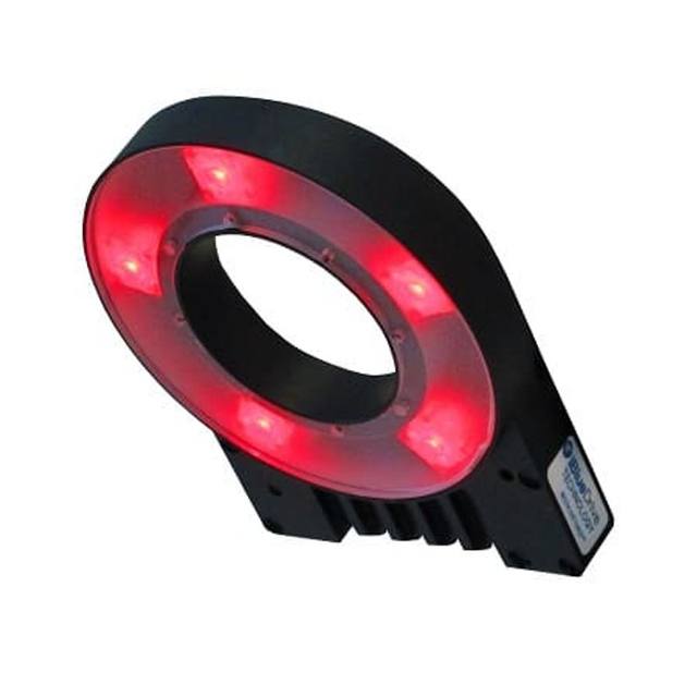
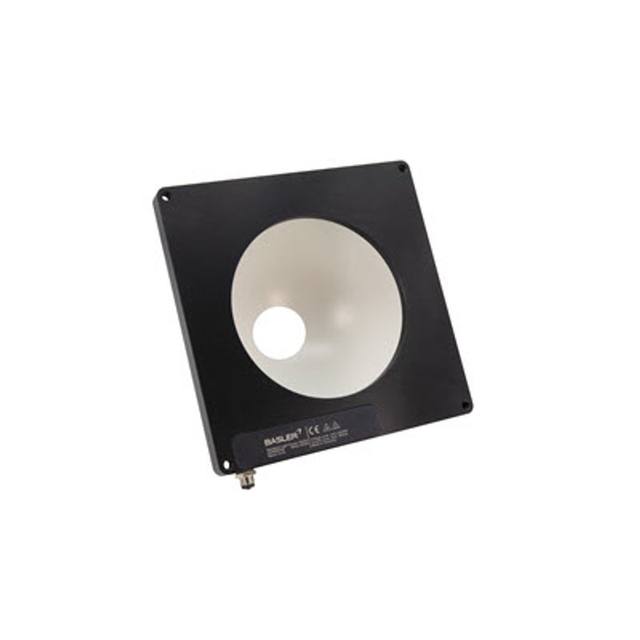
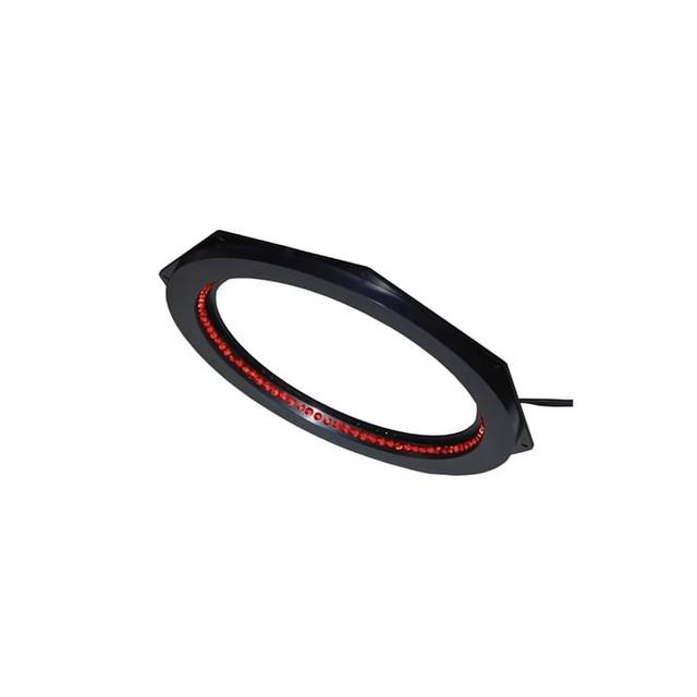
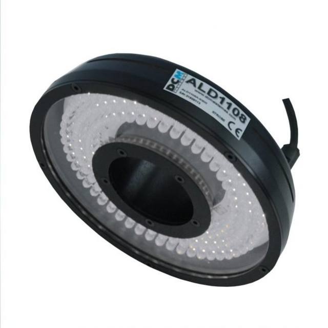
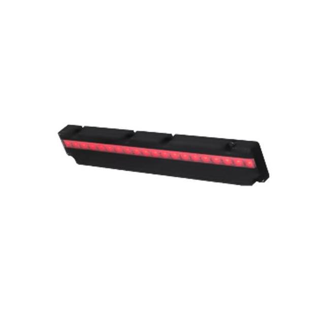
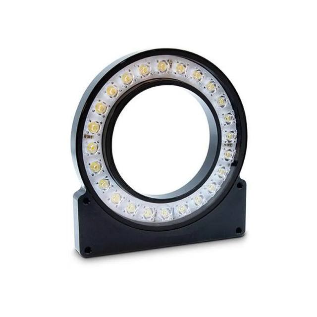
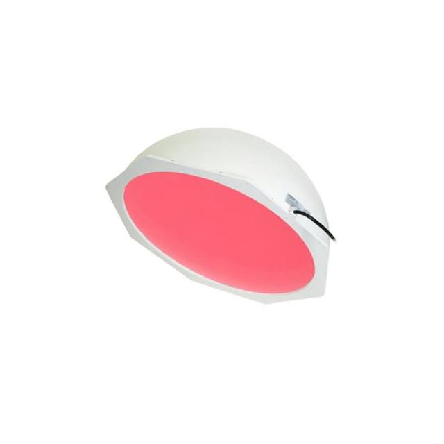
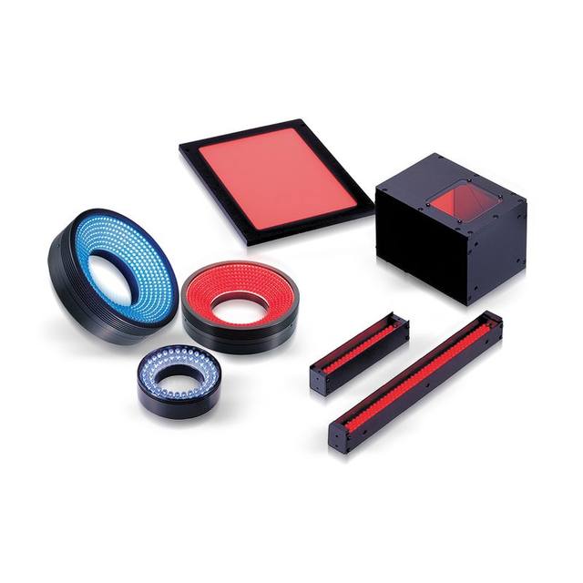
The most effective technique for surface relief is dark-field illumination: light projected at a low, grazing angle so that the intact surface reflects it away from the lens and appears dark, while any edge, scratch, dent or raised feature scatters light back toward the sensor and lights up brightly against that dark background. This is the inverse of a normal image and it is exactly what surface defect detection needs, because it converts a few-micron change in relief into a high-contrast bright-on-dark feature. The same geometry makes embossing and engraving legible by casting controlled shadows along the relief.
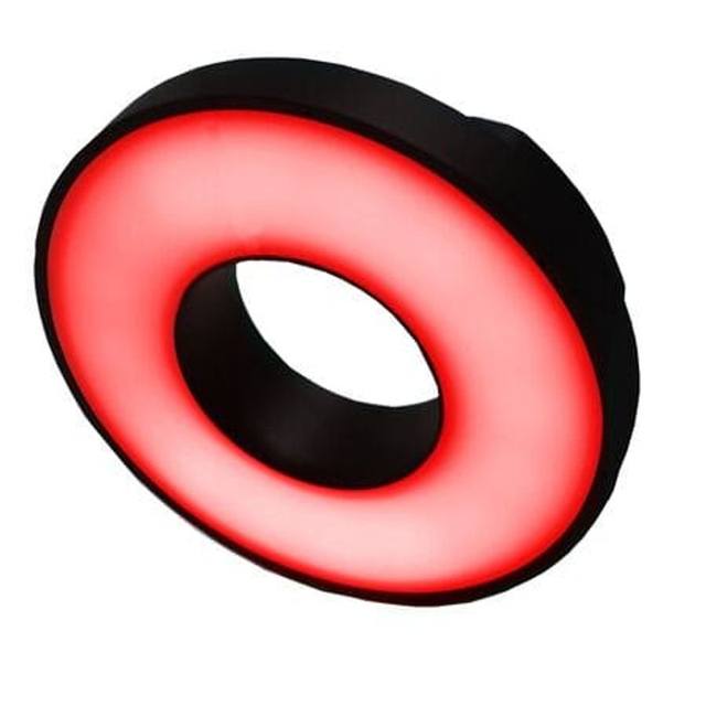
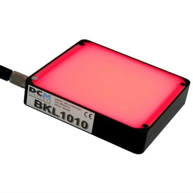
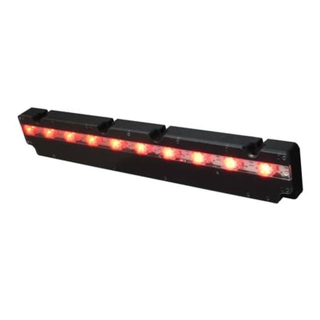
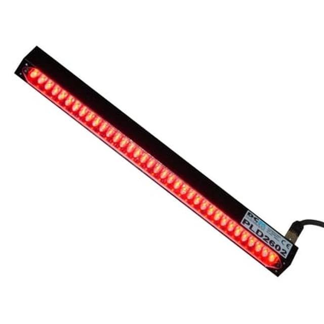
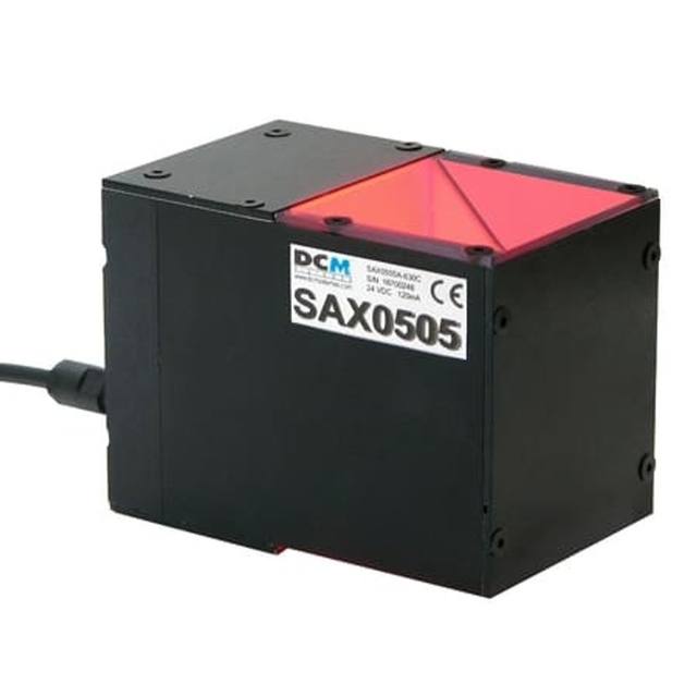
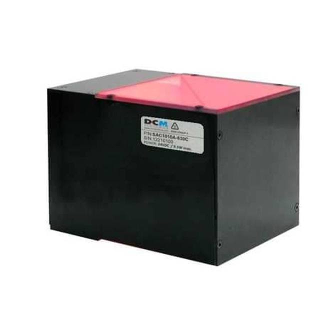
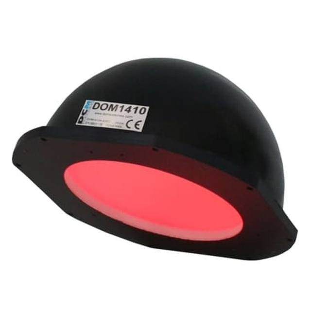
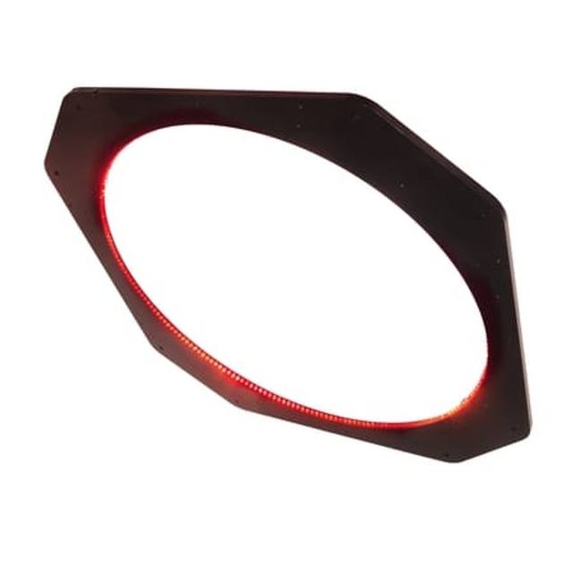
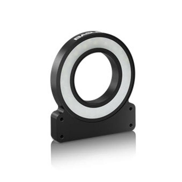
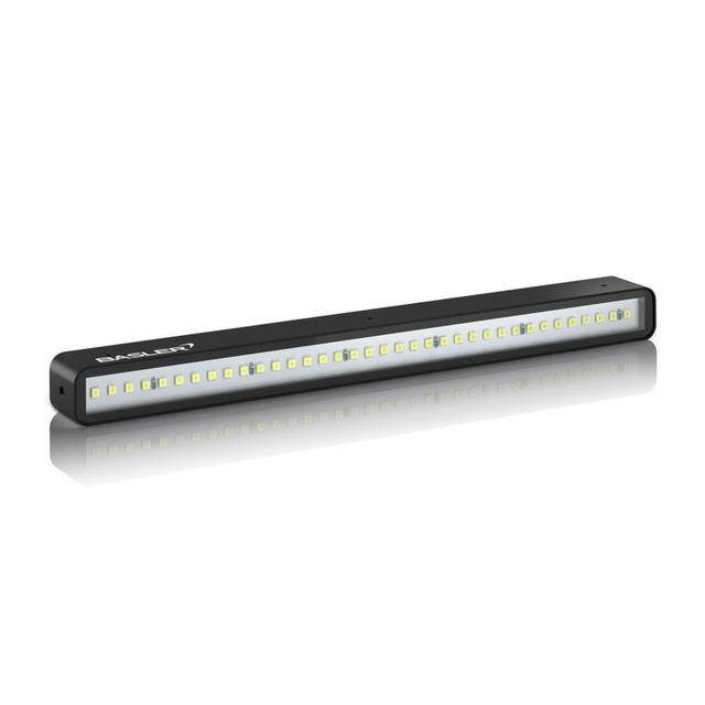
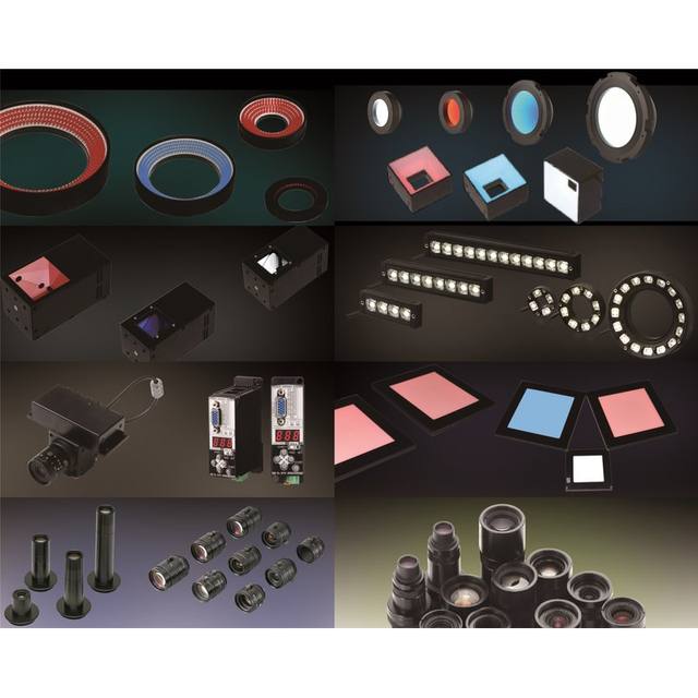
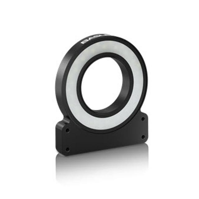
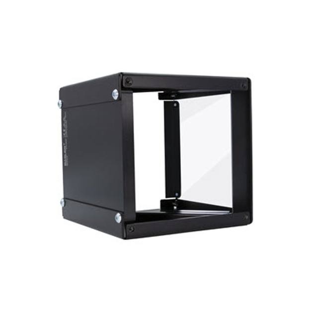
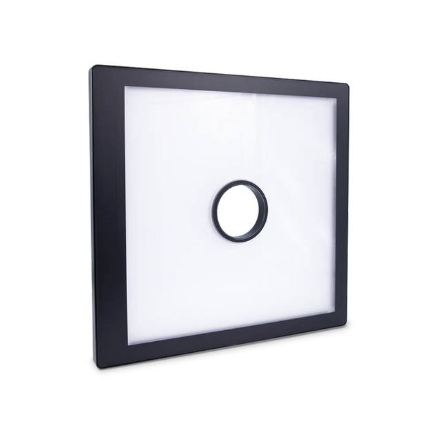
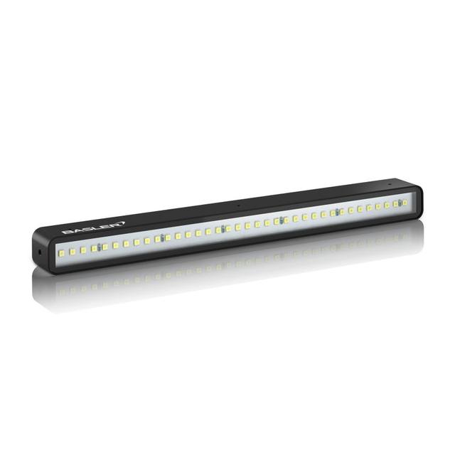
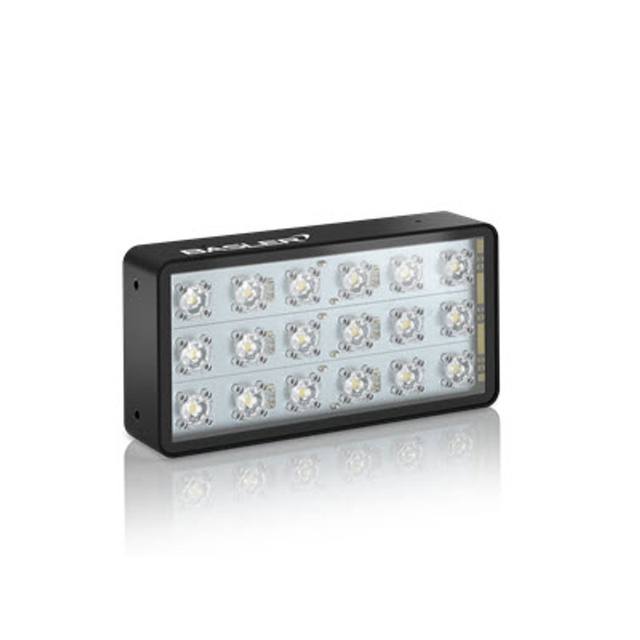
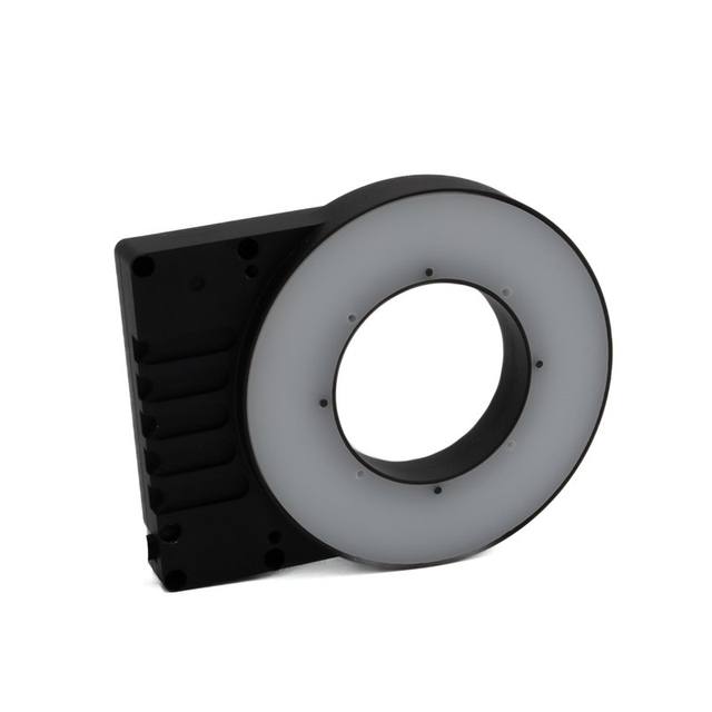
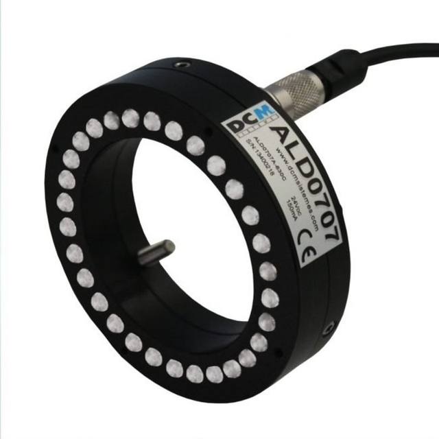
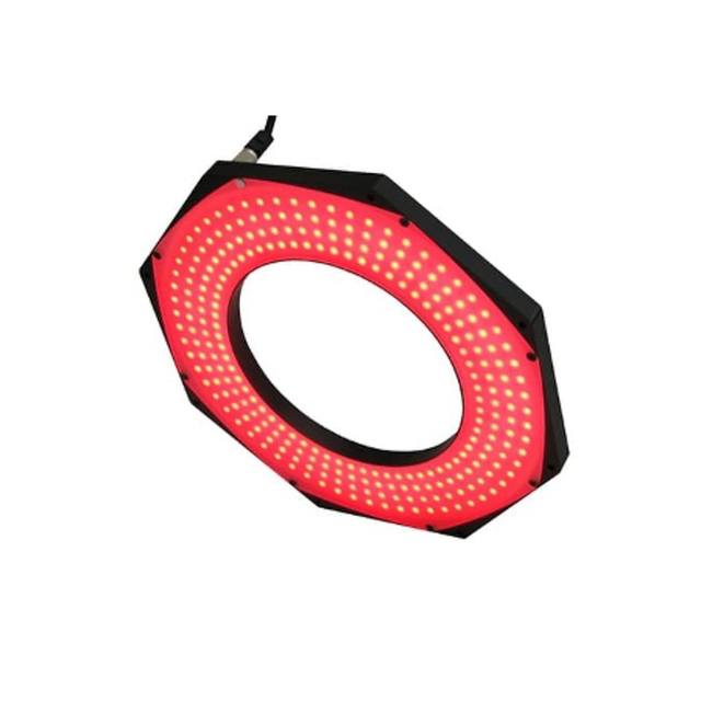
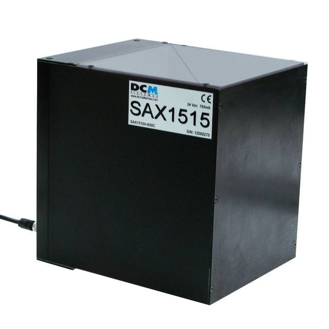
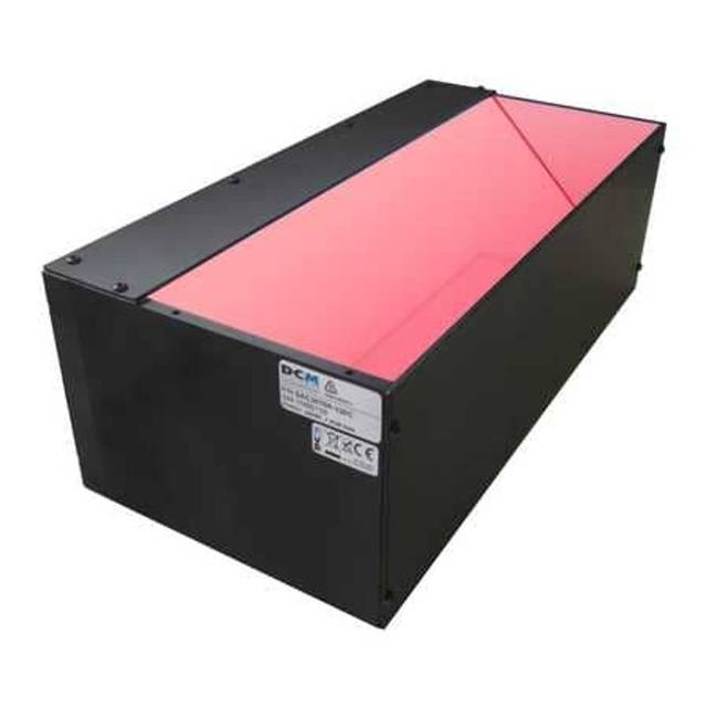
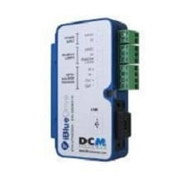
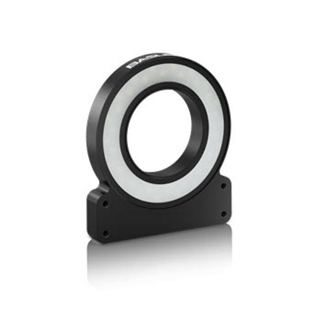
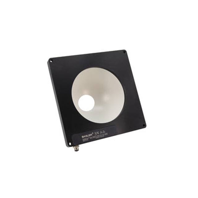
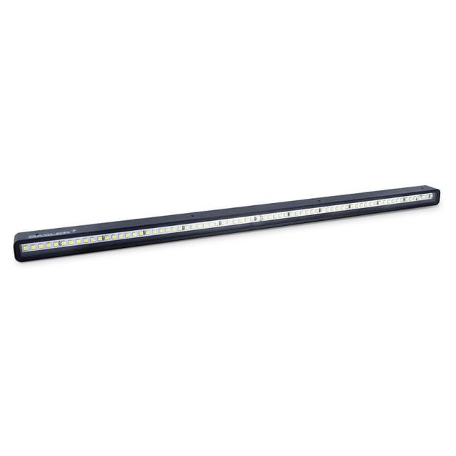
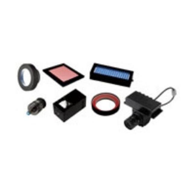
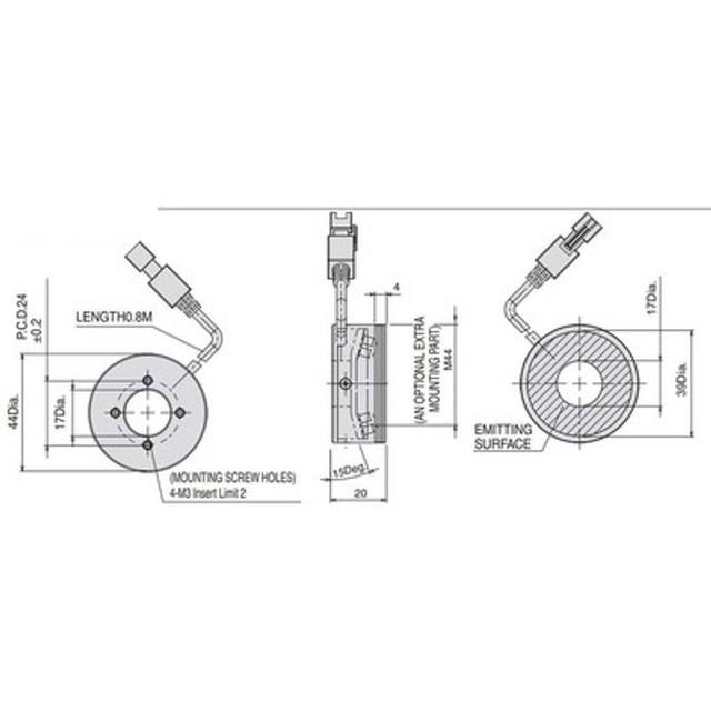
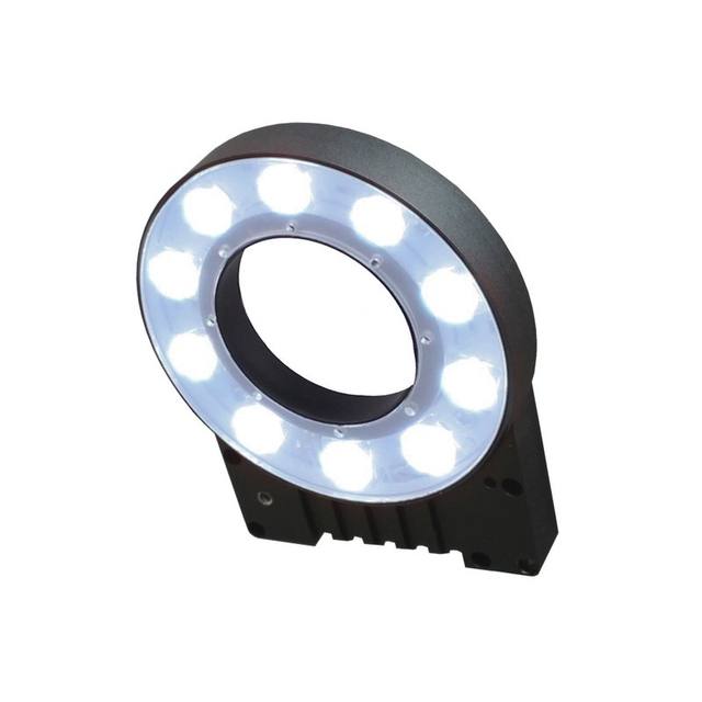
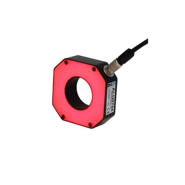
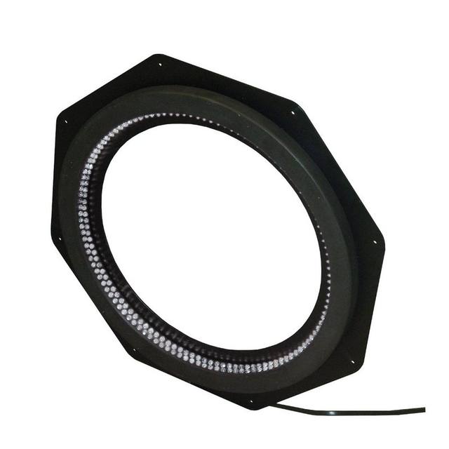
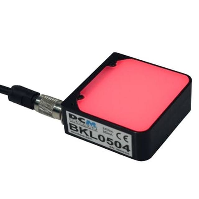
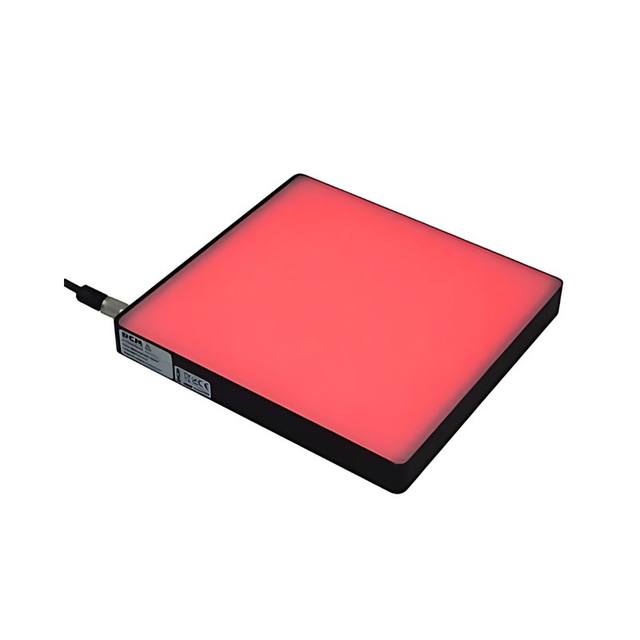
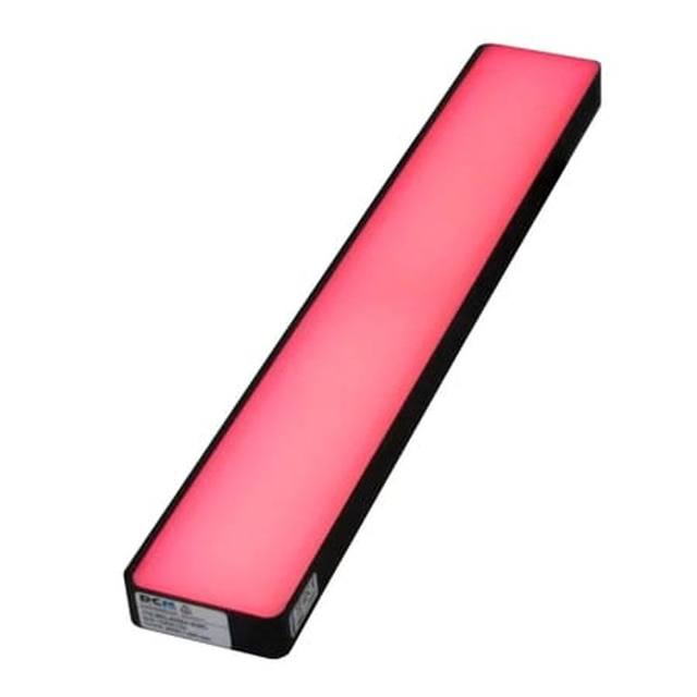
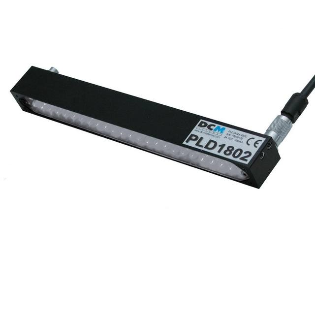
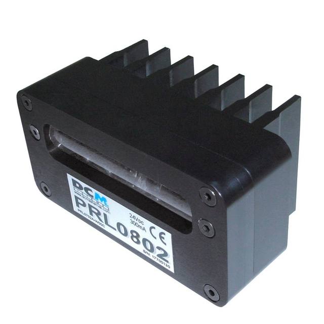
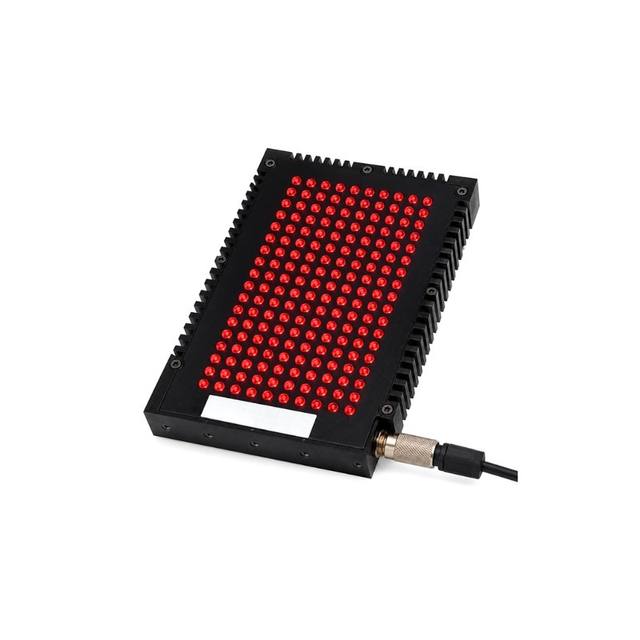
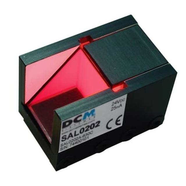
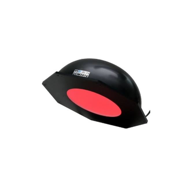
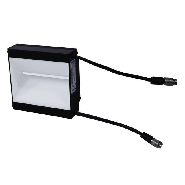
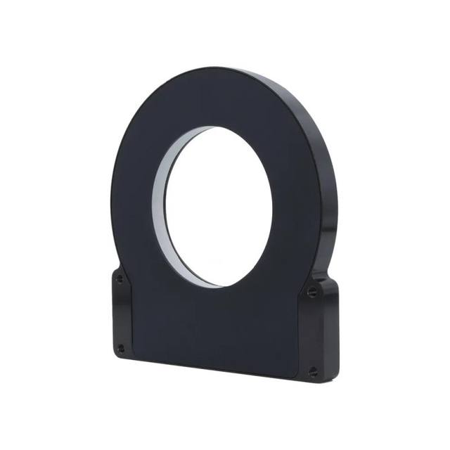
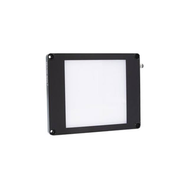
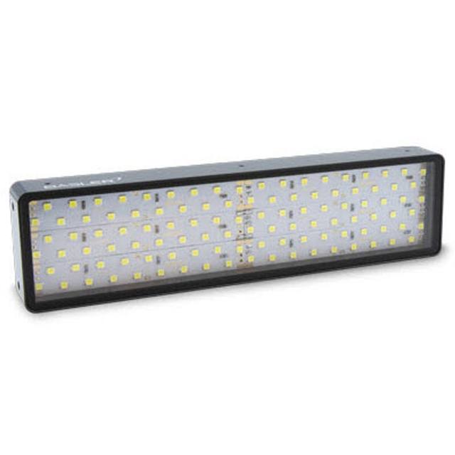
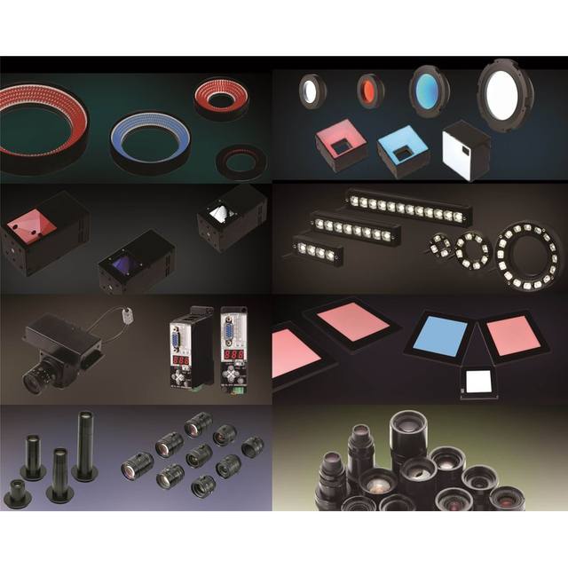
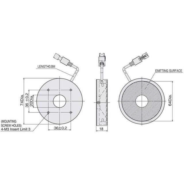
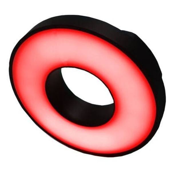
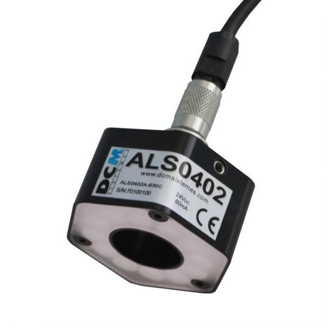
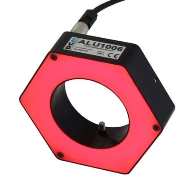
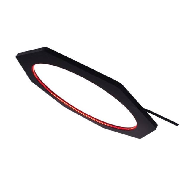
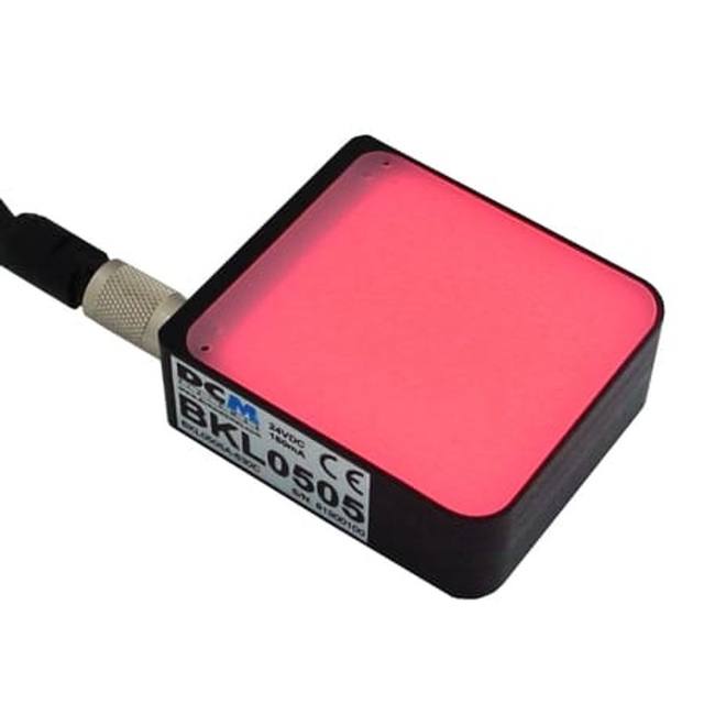
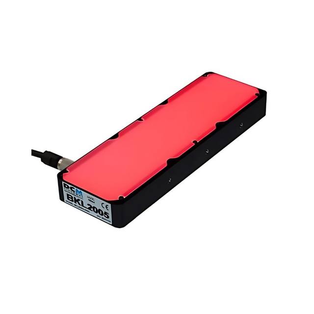
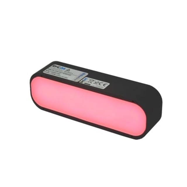
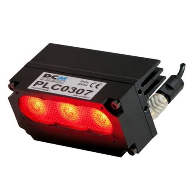
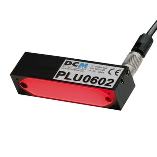
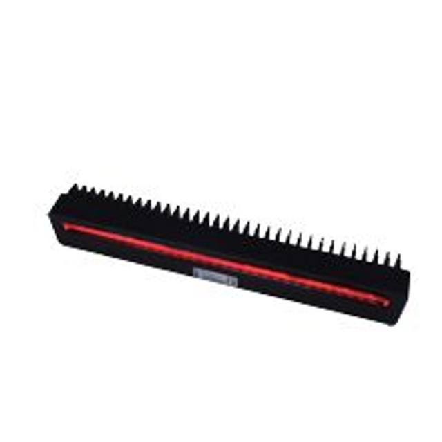
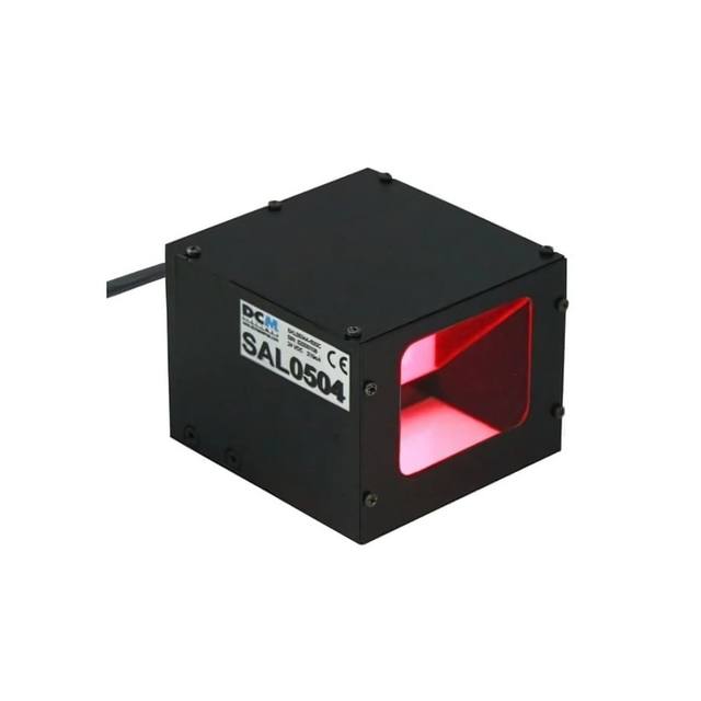
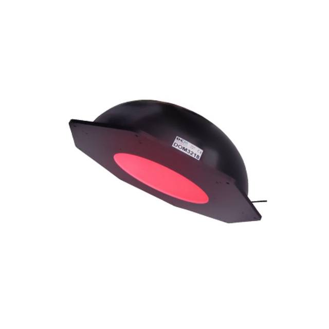
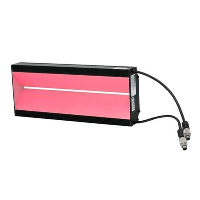
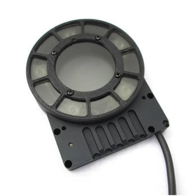
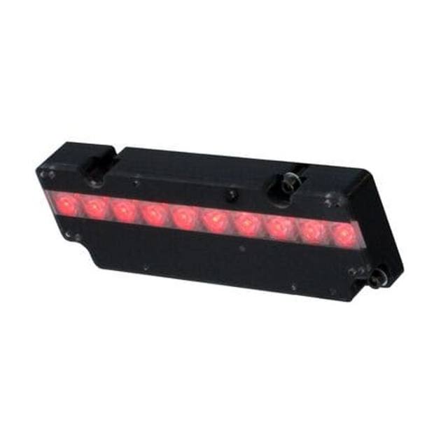
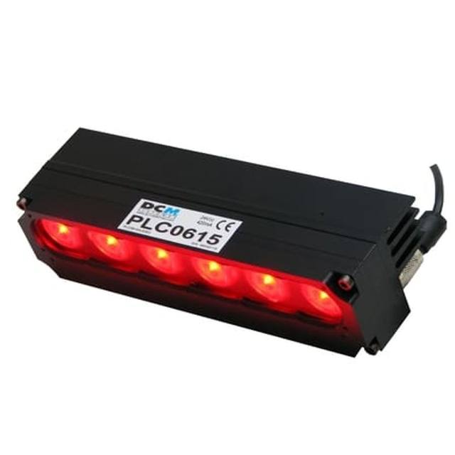
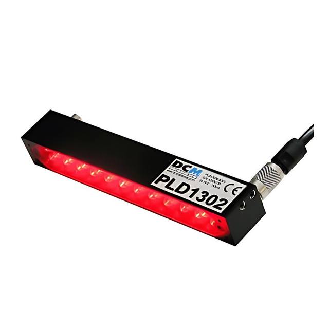
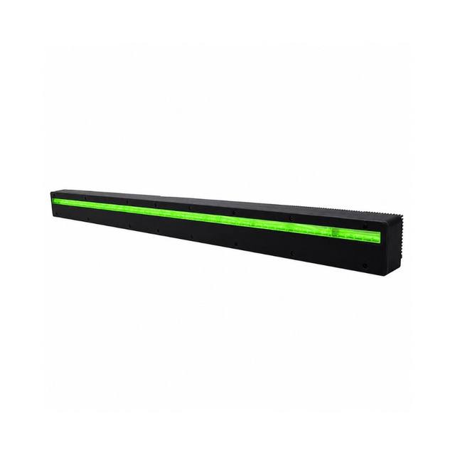
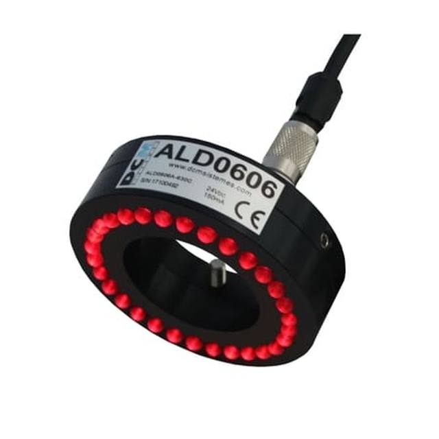
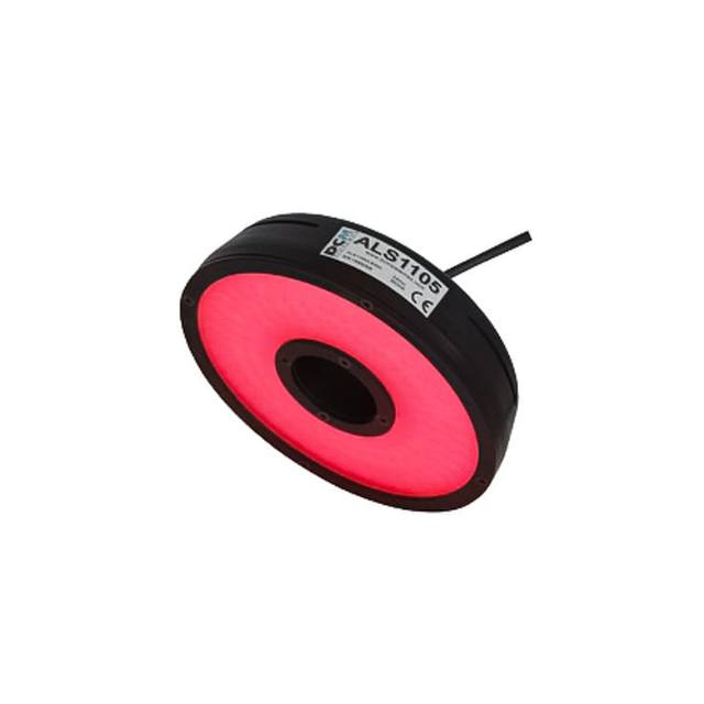
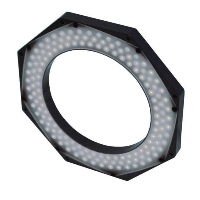
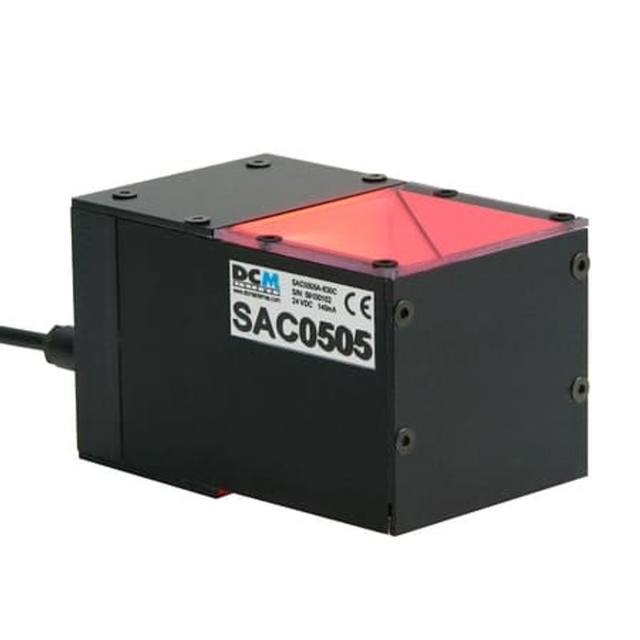
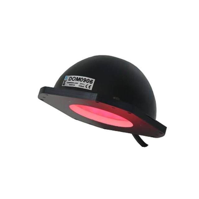
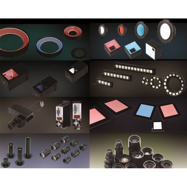
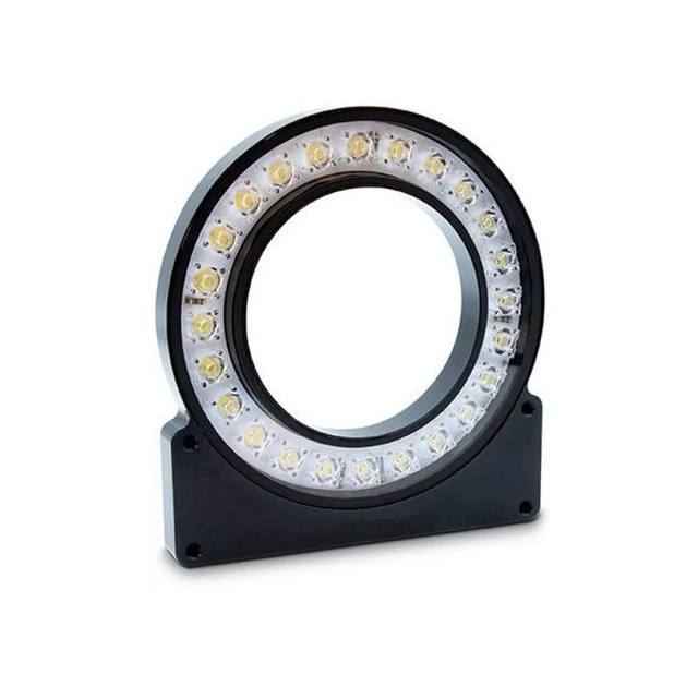
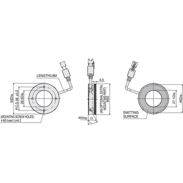
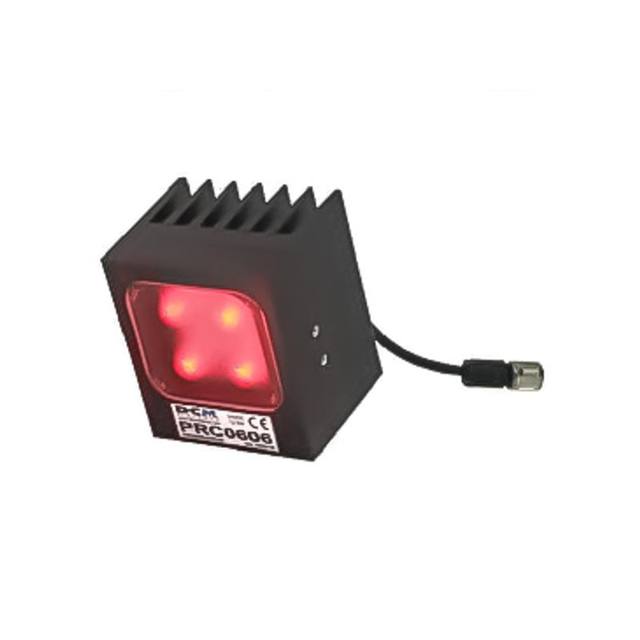
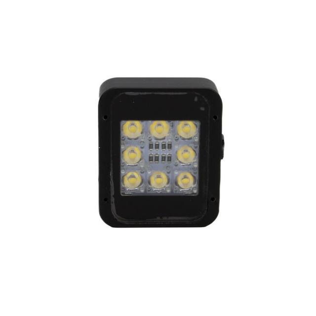
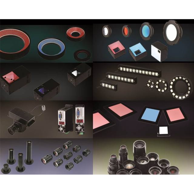
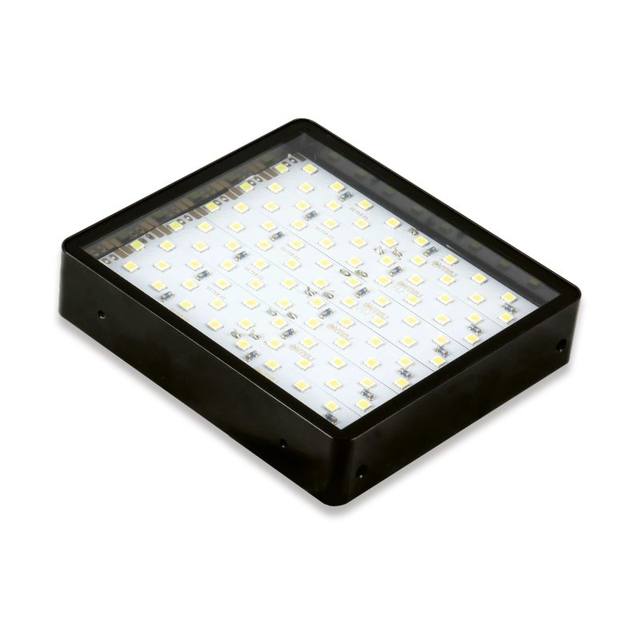
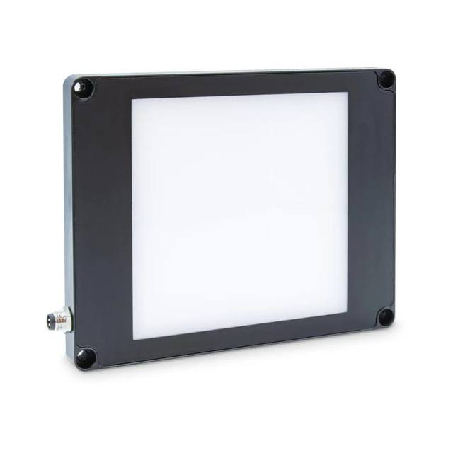
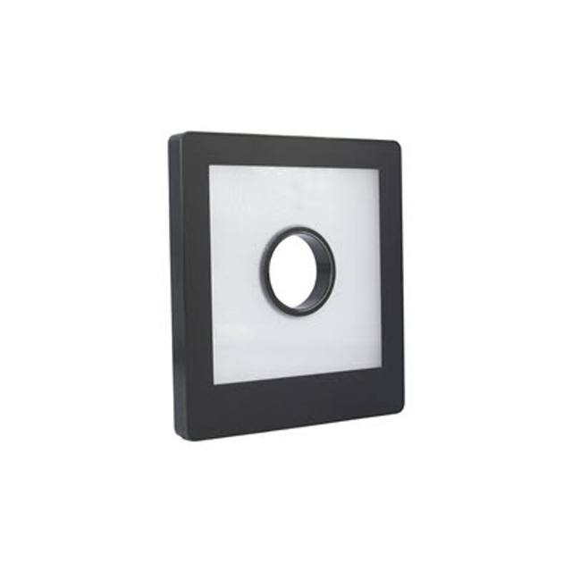
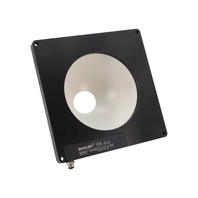
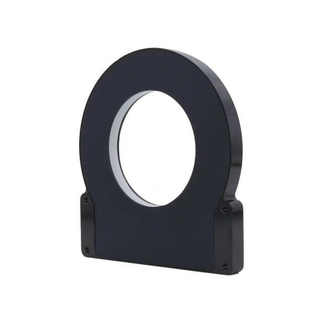
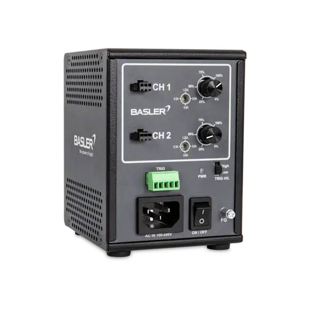
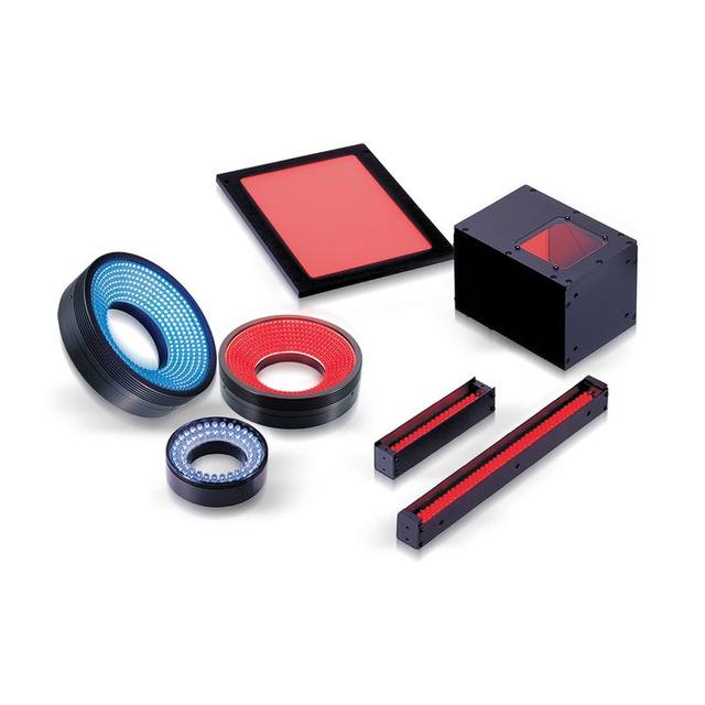
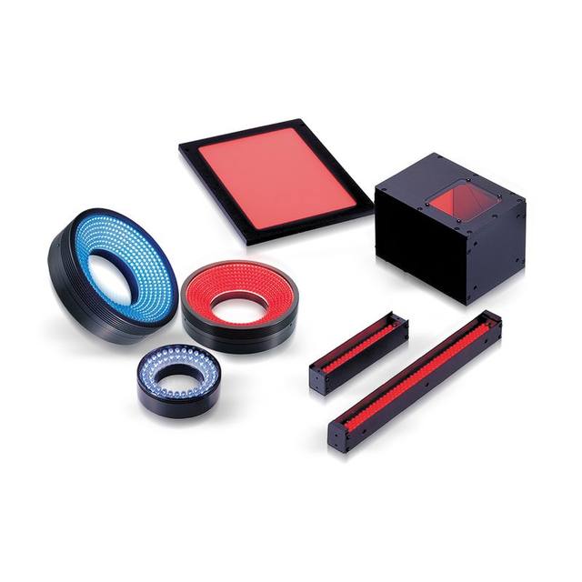
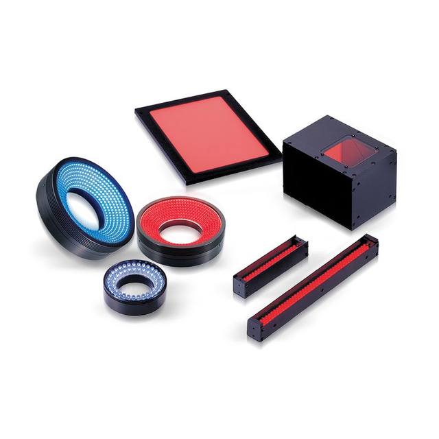
Getting this right is a geometry exercise, not just a brightness one. The angle of incidence, the direction of the light relative to the likely defect orientation, the working distance and the uniformity of the line all determine whether the defect signal is repeatable across the field. Scratches have direction, so a single-direction grazing light can be blind to defects running parallel to it; multi-directional or low-angle ring arrangements, or sequential captures from different directions, are often used to catch defects of any orientation. High-intensity, tightly-controlled illumination from a lighting specialist such as DCM Sistemes is important here, because grazing geometry is inherently light-inefficient and line scan acquisition concentrates the requirement onto a single bright line.
In practice you should expect to prototype several lighting geometries against real defective samples. Bright-field, dark-field, low-angle and coaxial each expose different defect classes, and the winning configuration is the one that maximises defect-to-background contrast for your specific material, finish and defect catalogue.
- Bright-field (diffuse, on-axis): good for colour, print and stains; weak on relief.
- Low-angle / dark-field (grazing): best for scratches, dents, edges and embossing; suppresses the flat background.
- Directional vs multi-directional: single-direction light can miss scratches running parallel to it, so combine angles for orientation-independent detection.
- Match light spectrum and intensity to the material; specular and dark surfaces need careful angle control and high output.
Line scan, area scan and the speed question
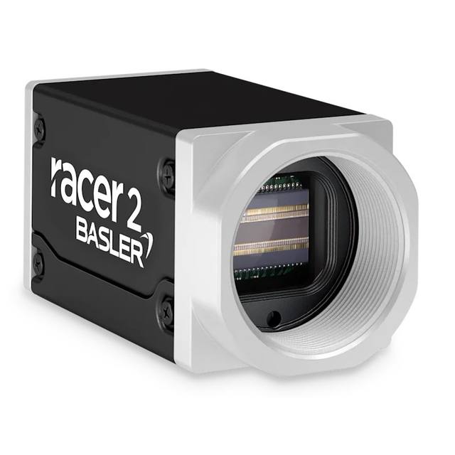
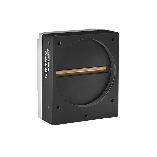
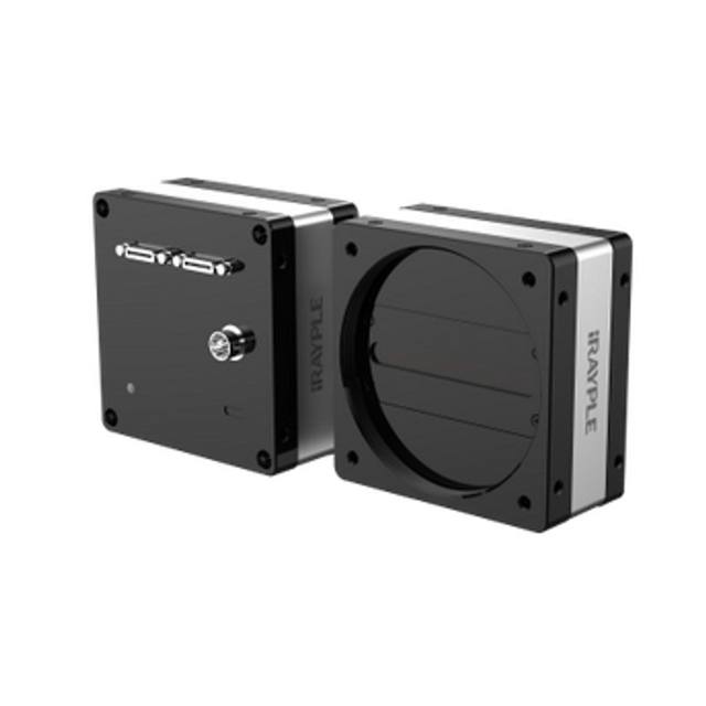
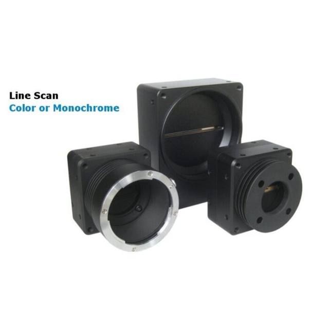
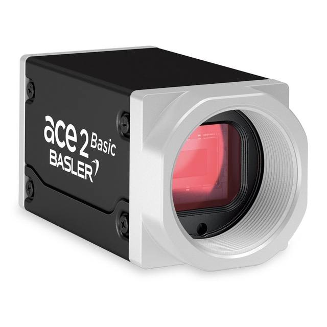
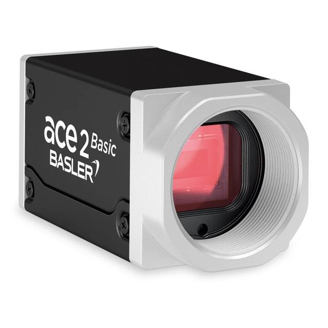
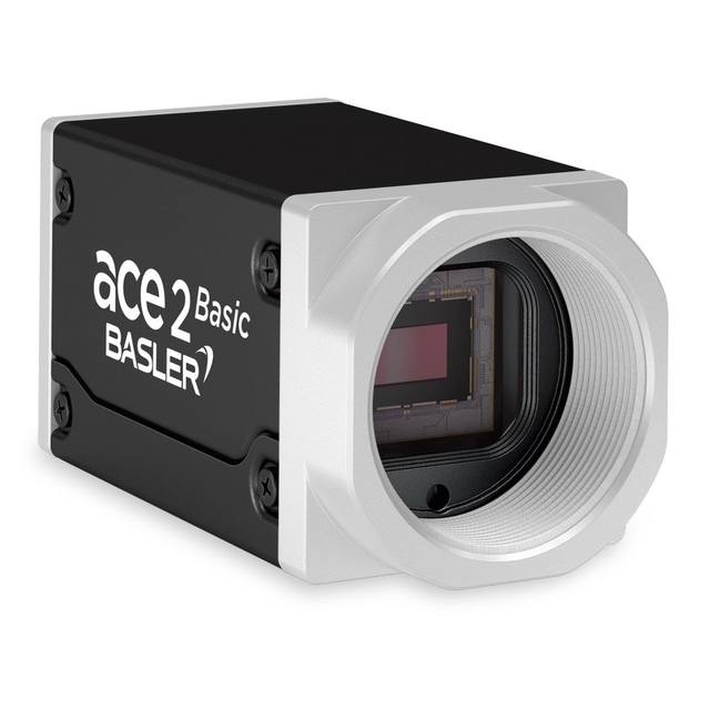
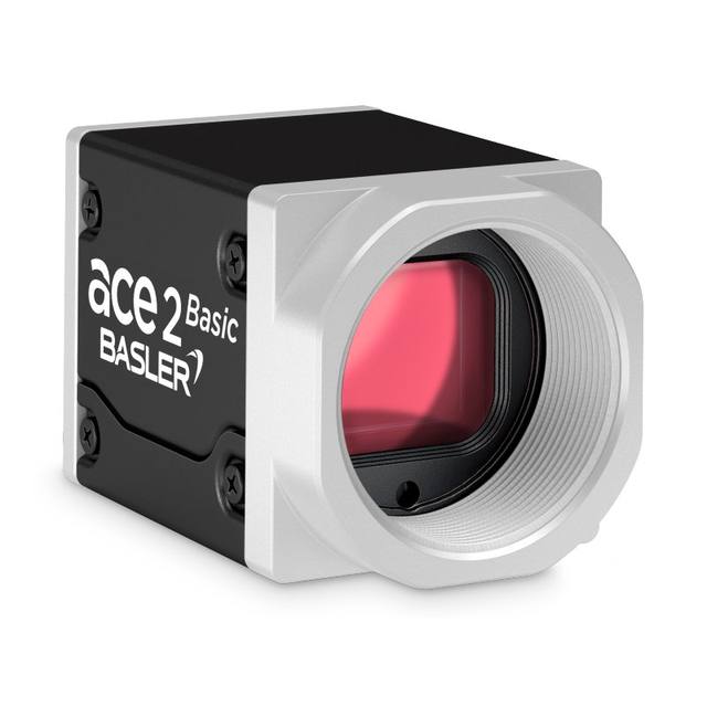
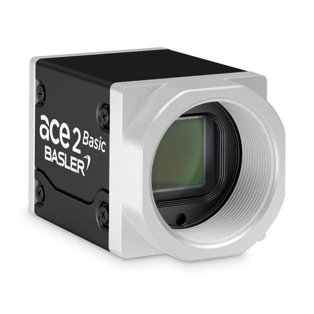
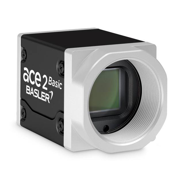
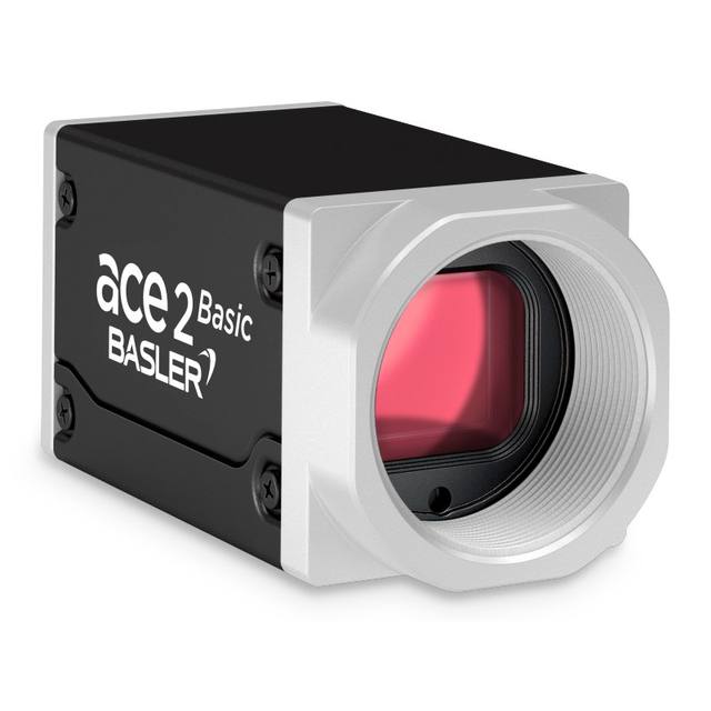
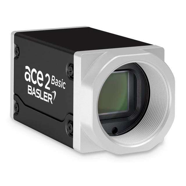
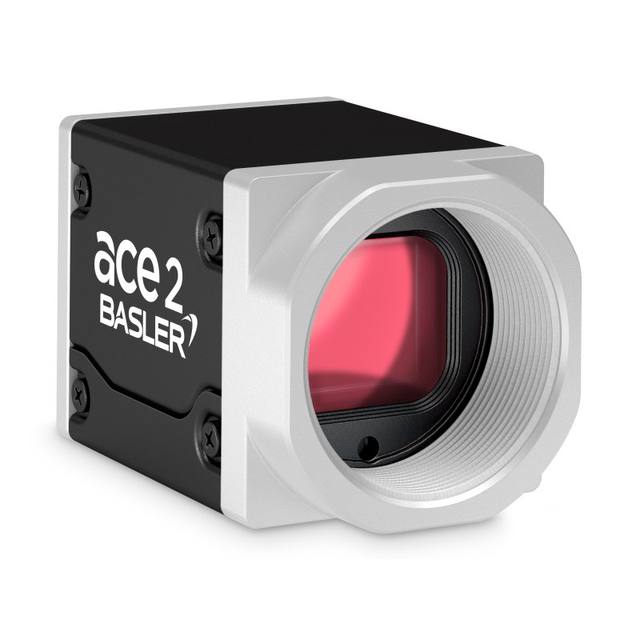
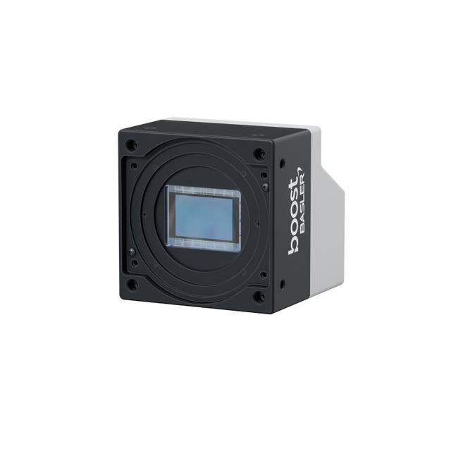
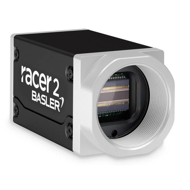
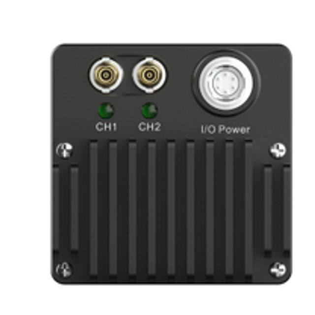
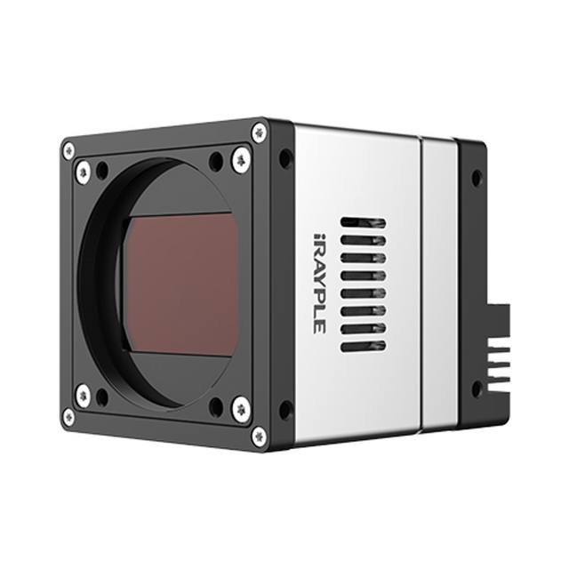
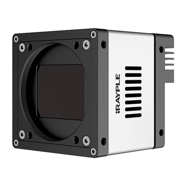
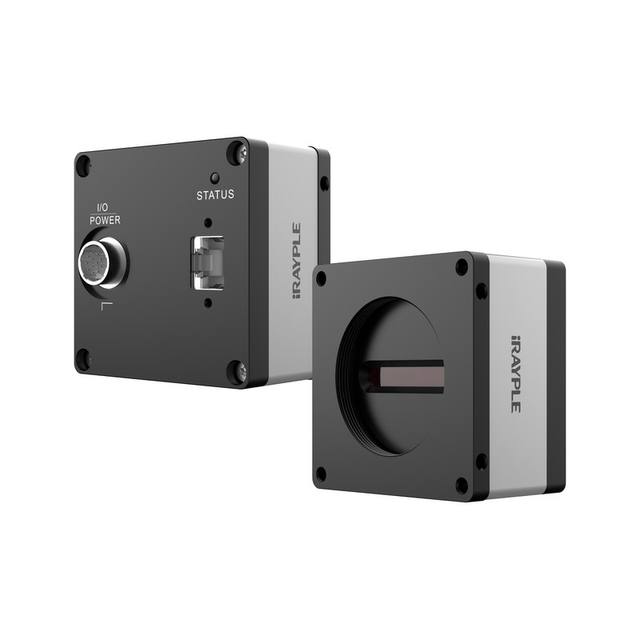
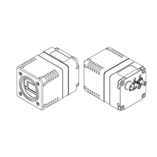
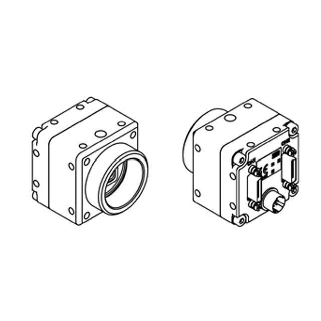
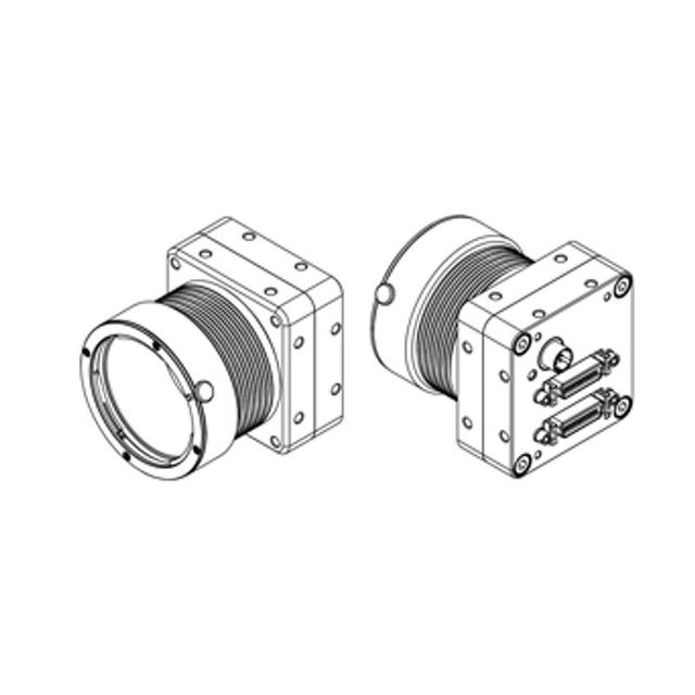
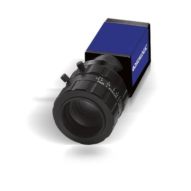
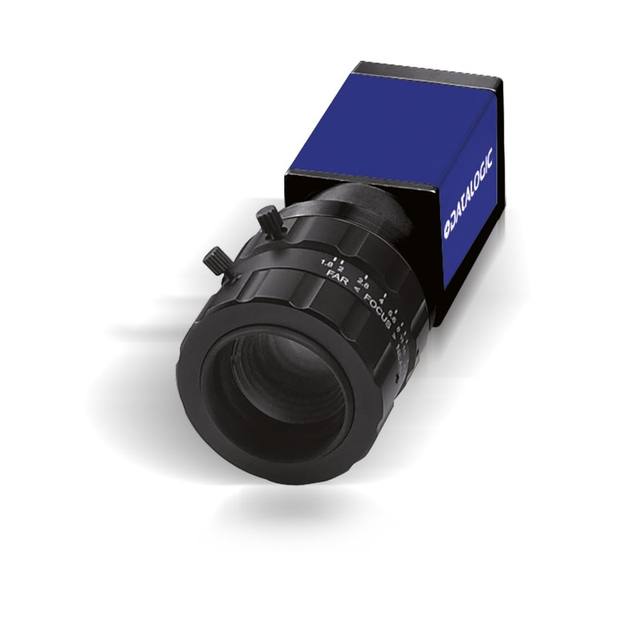
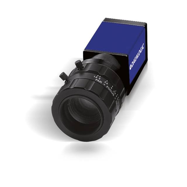
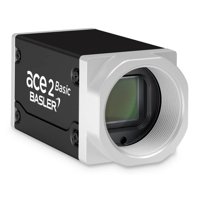
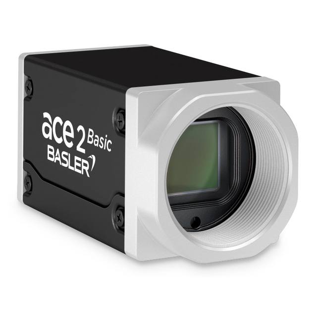
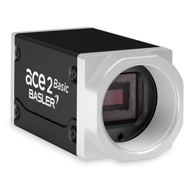
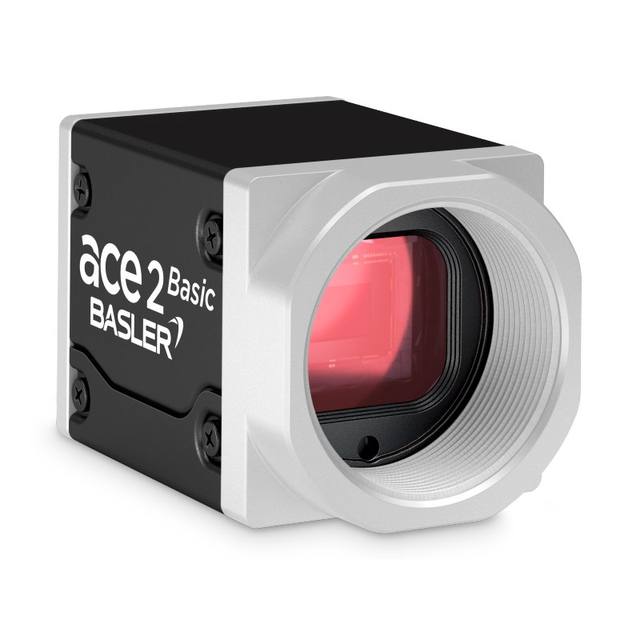
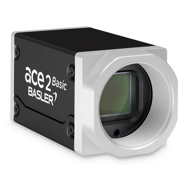
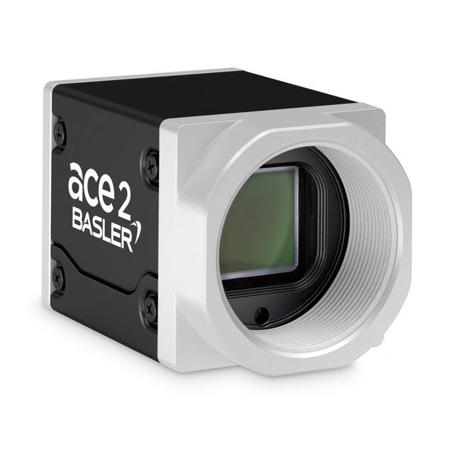
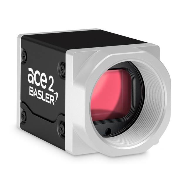
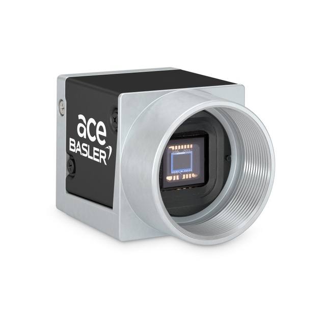
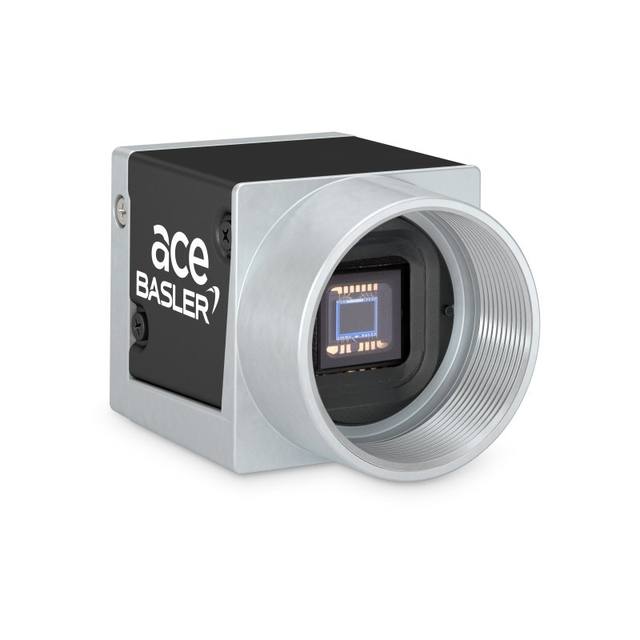
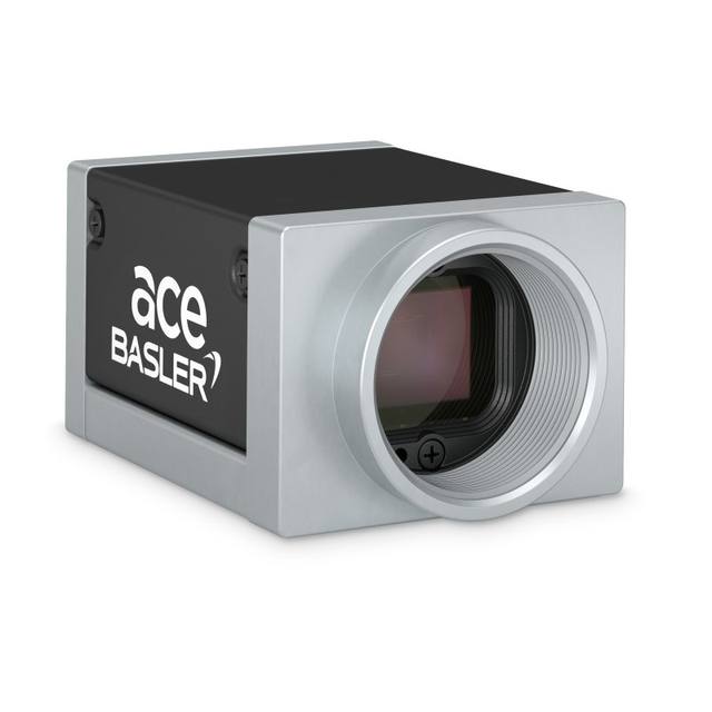
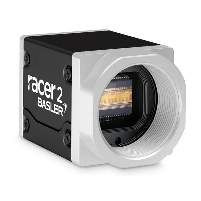
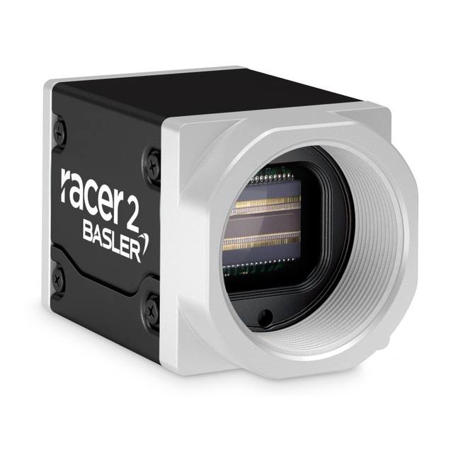
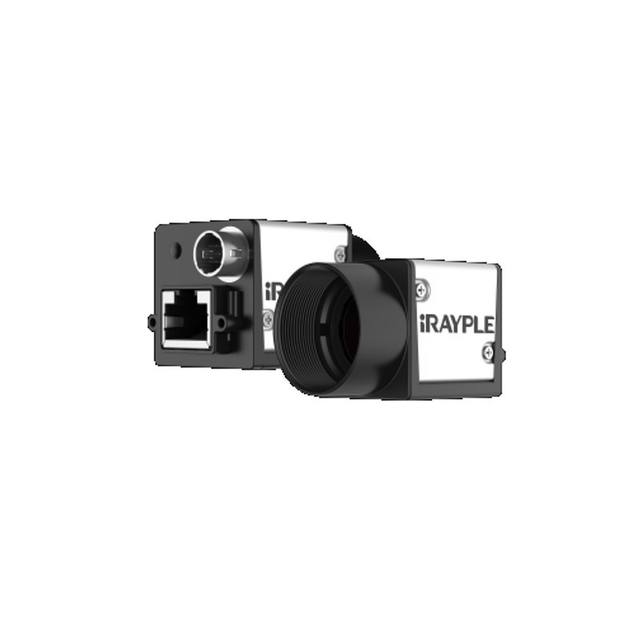
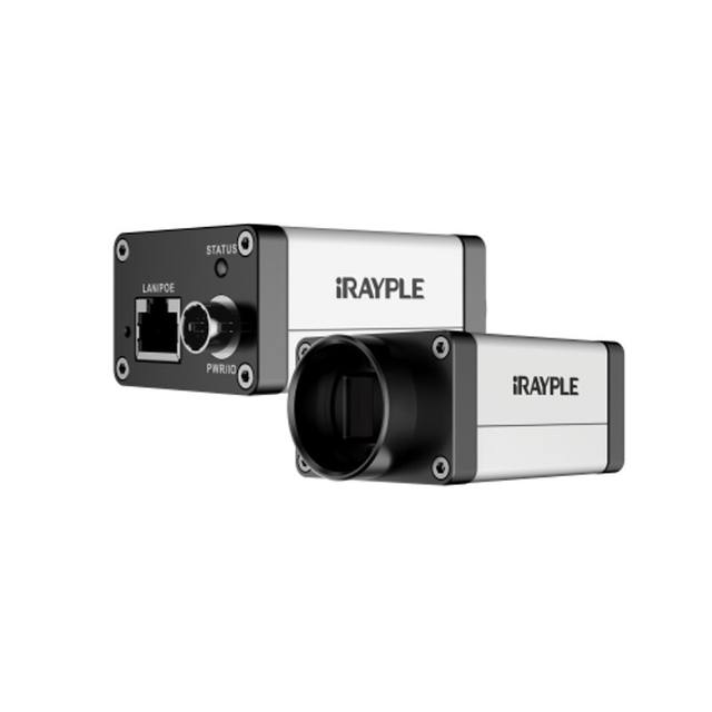
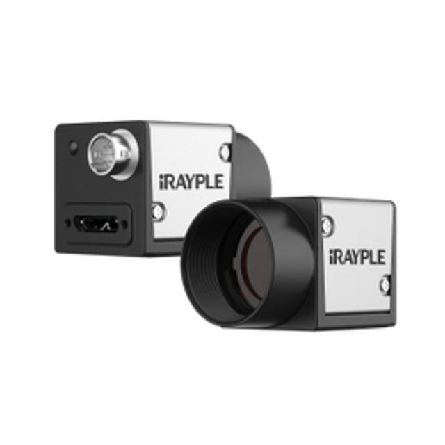
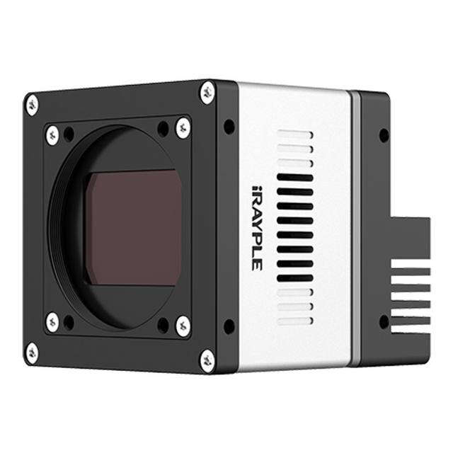
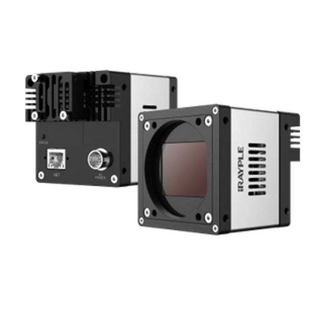
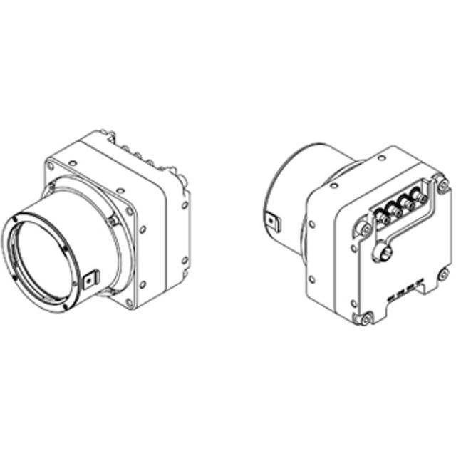
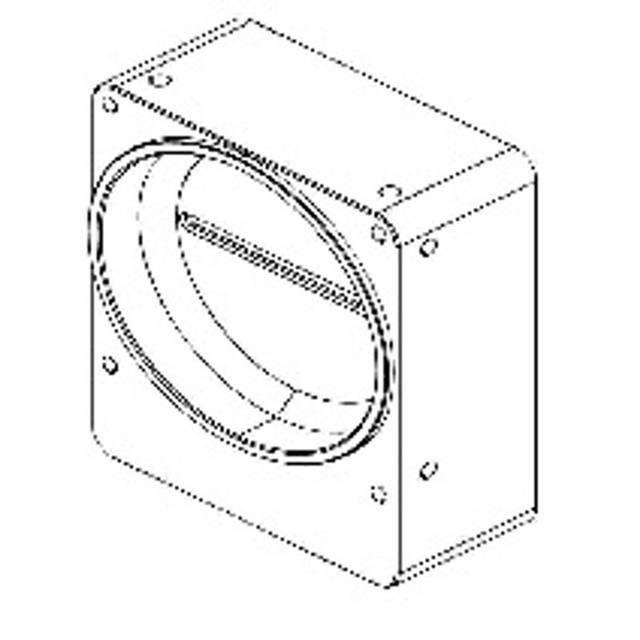
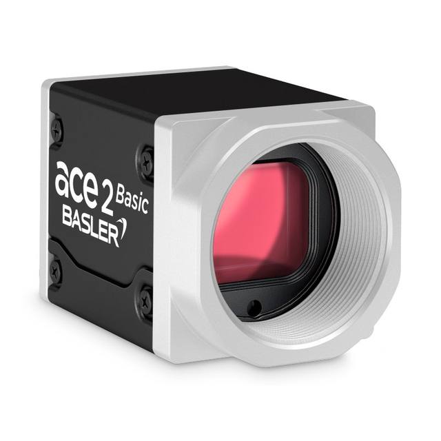
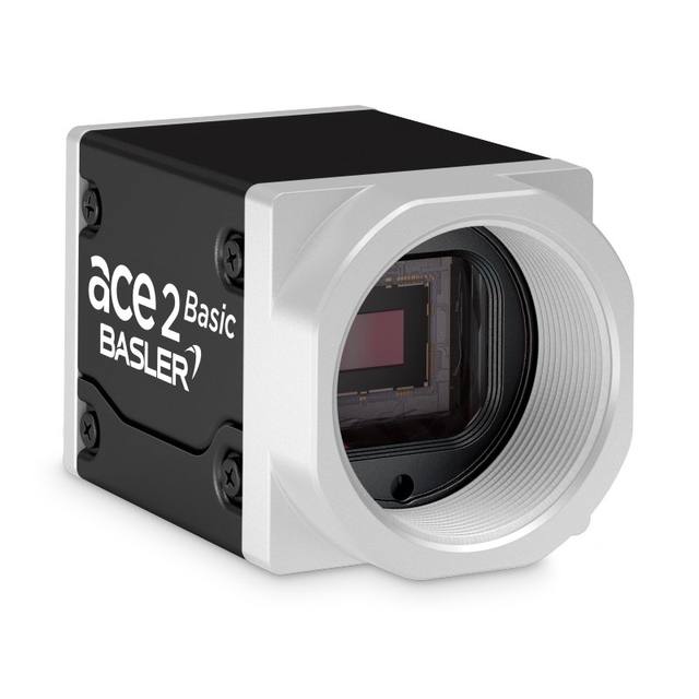
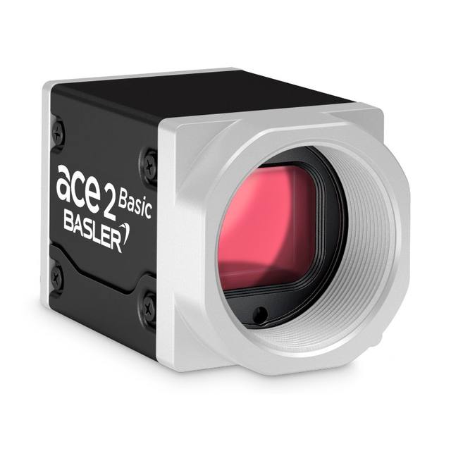
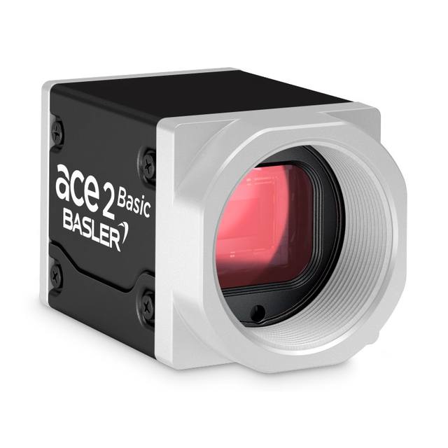
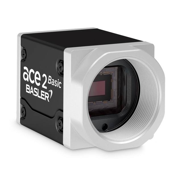
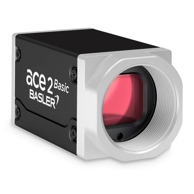
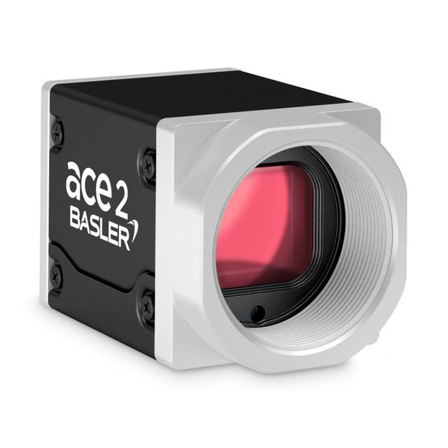
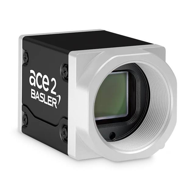
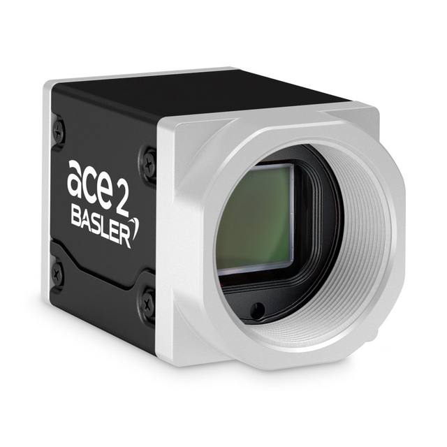
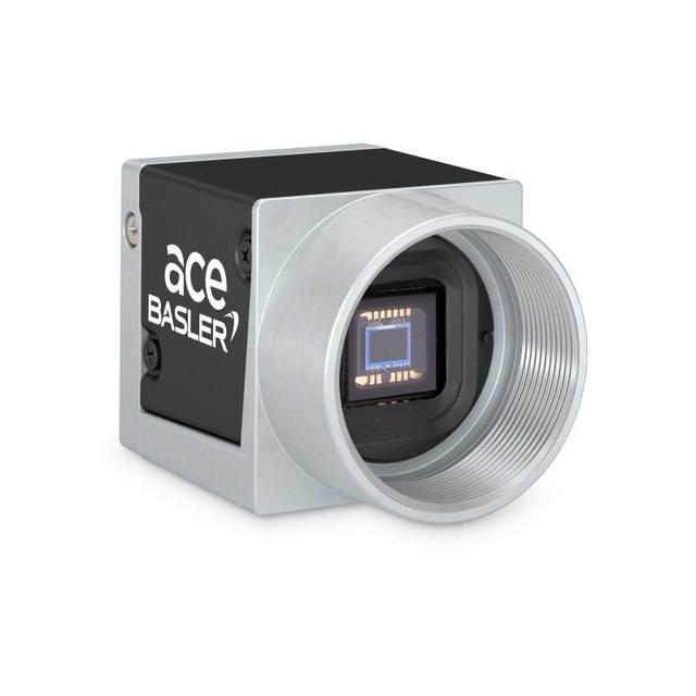
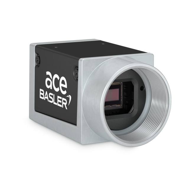
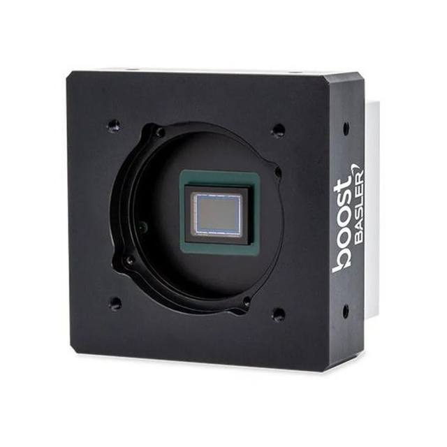
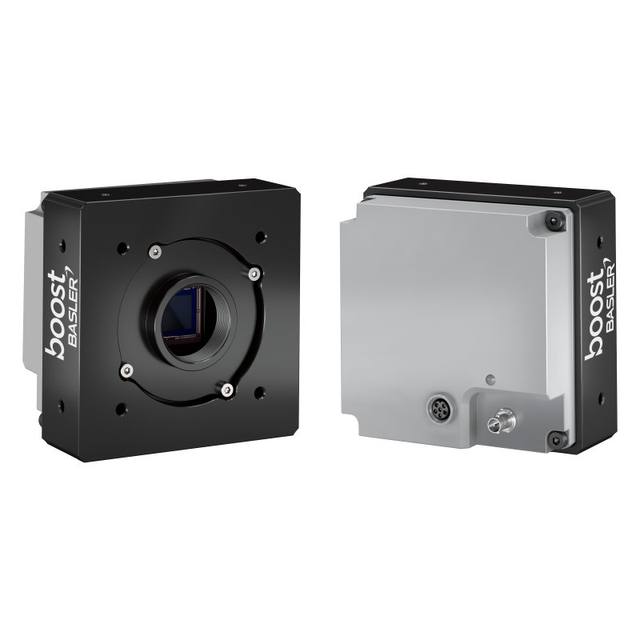
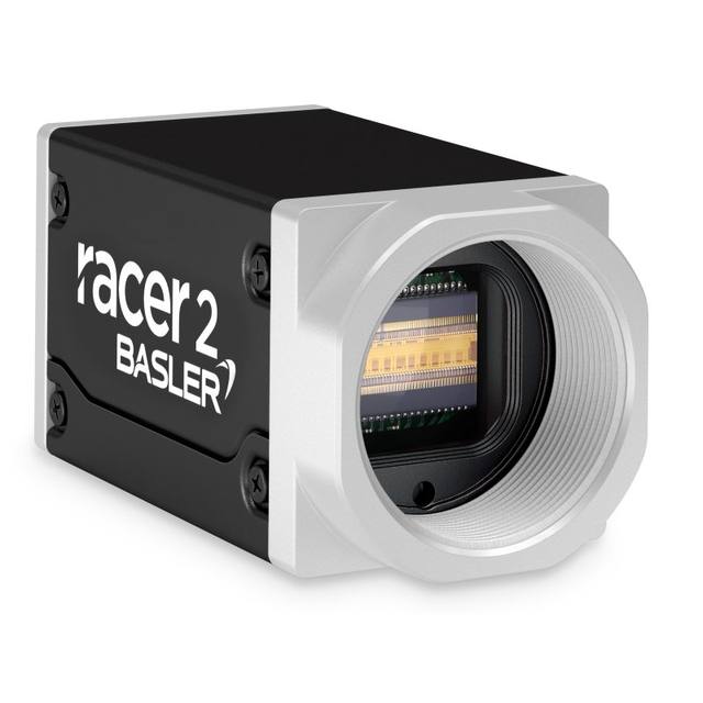
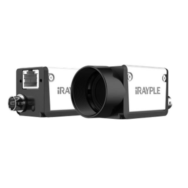
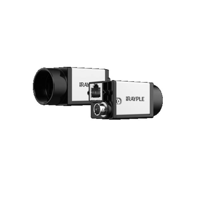
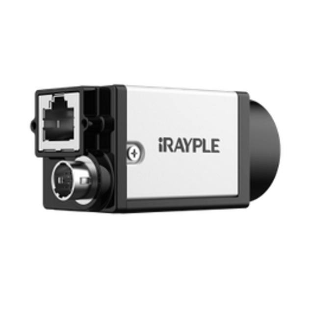
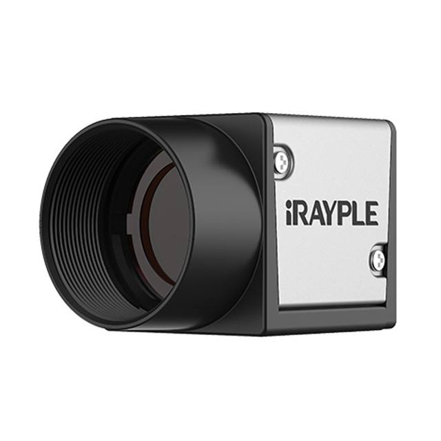
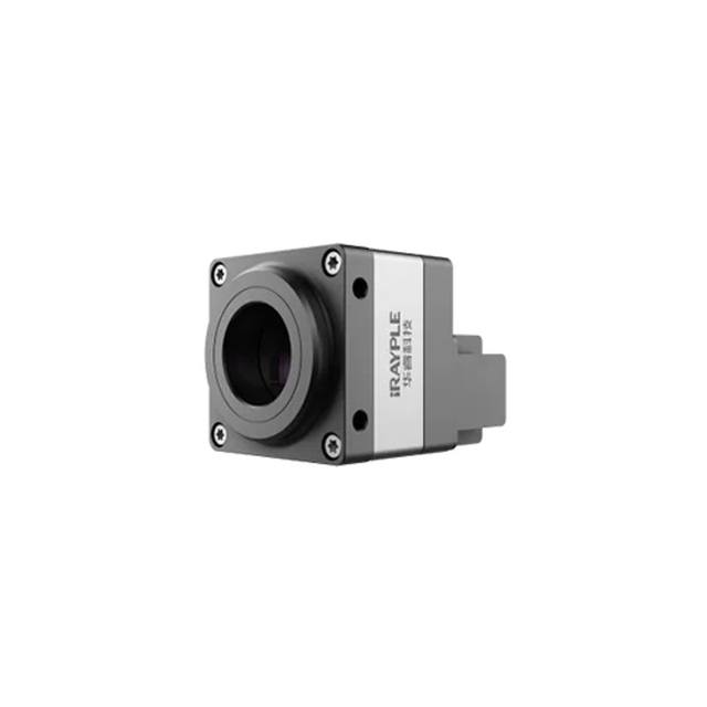
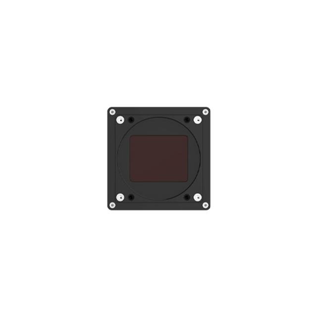
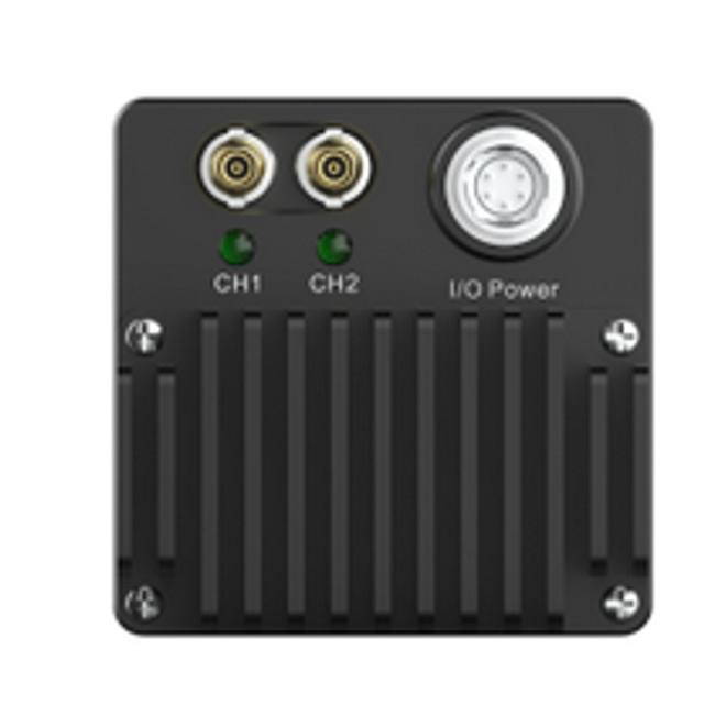
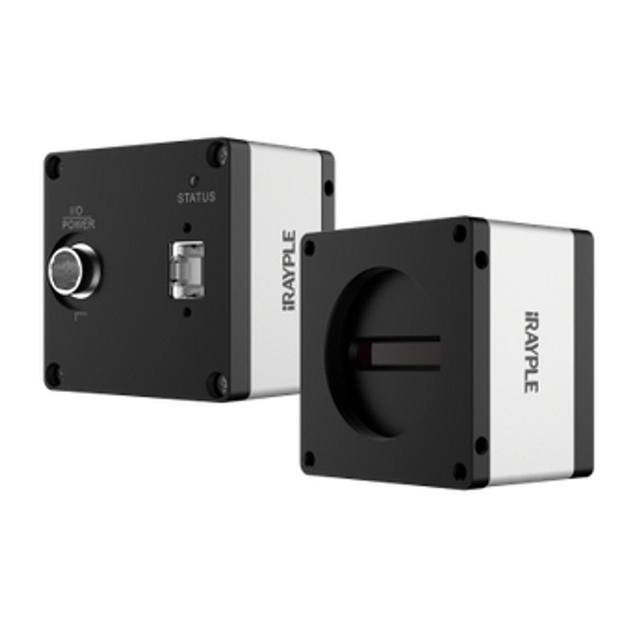
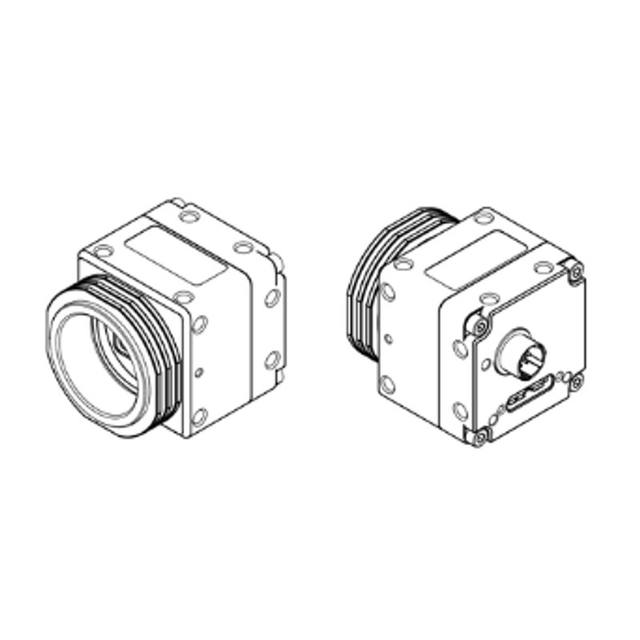
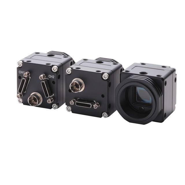
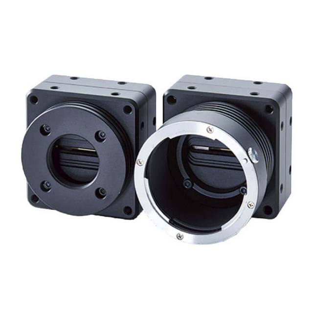
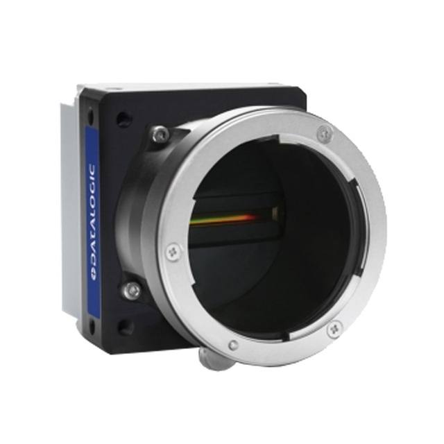
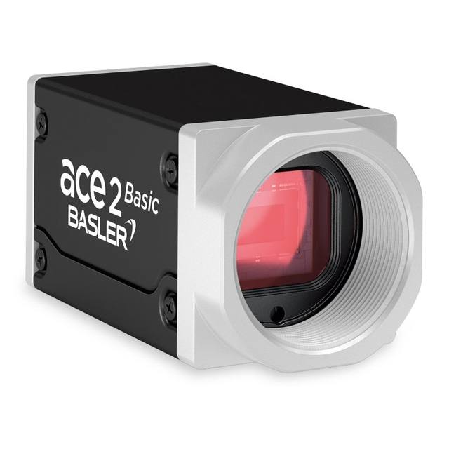
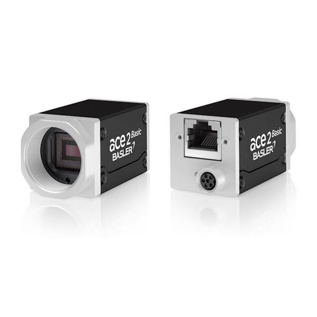
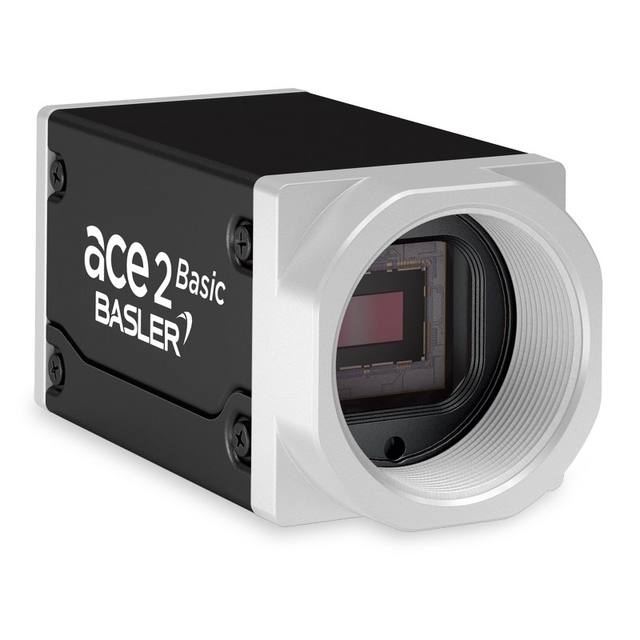
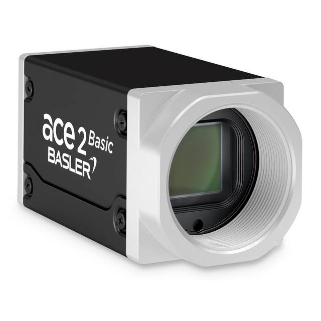
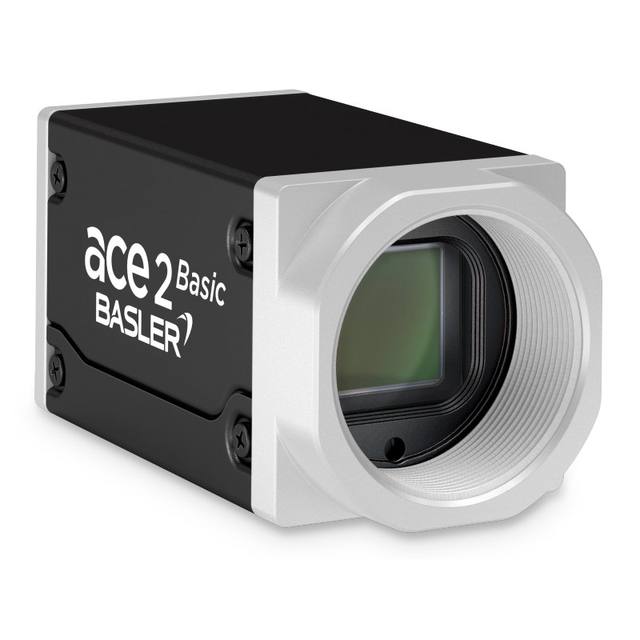
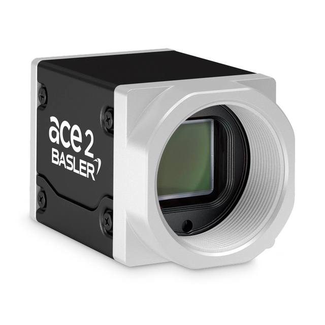
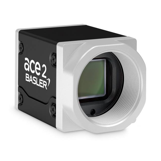
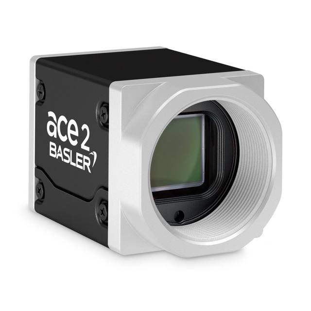
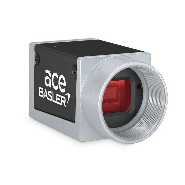
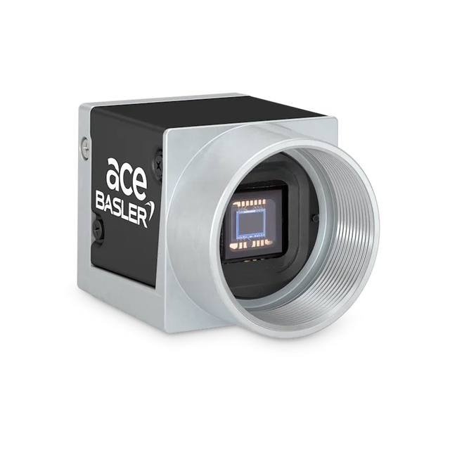
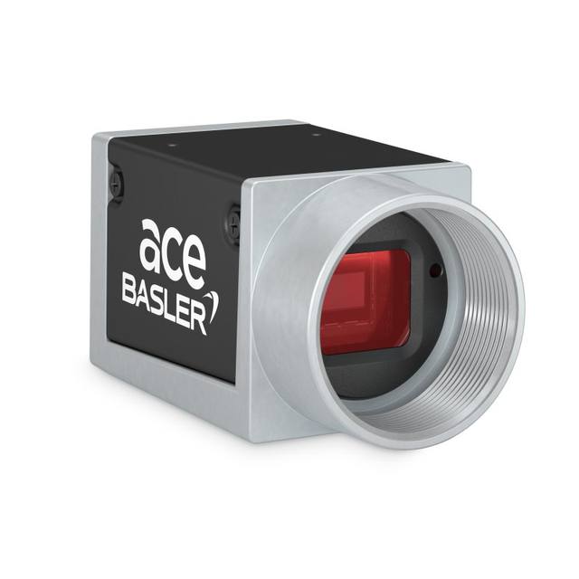
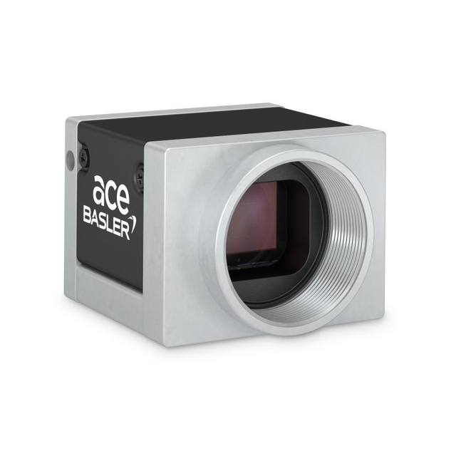
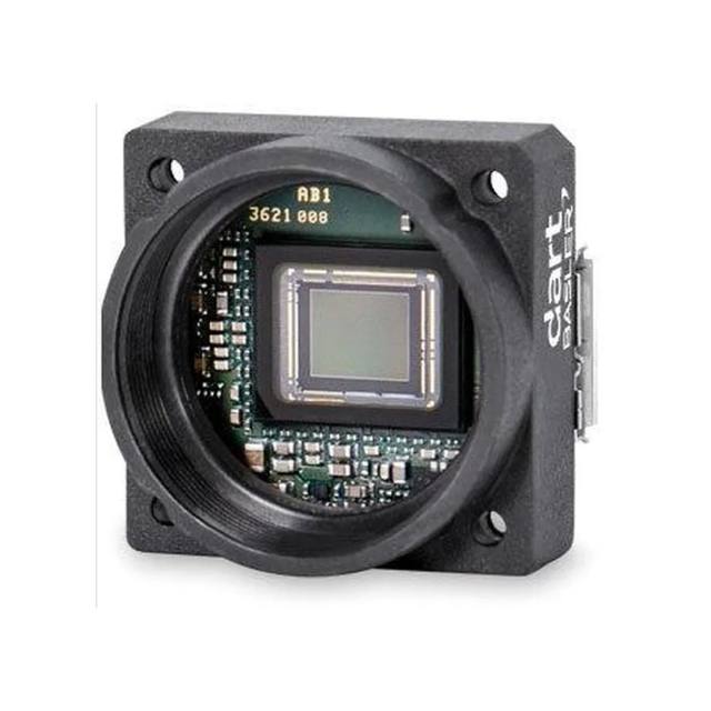
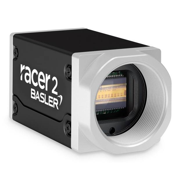
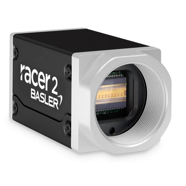
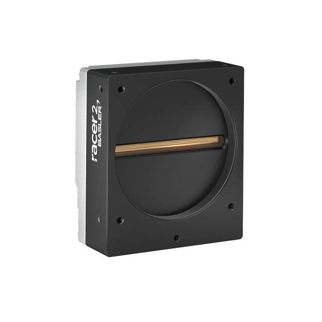
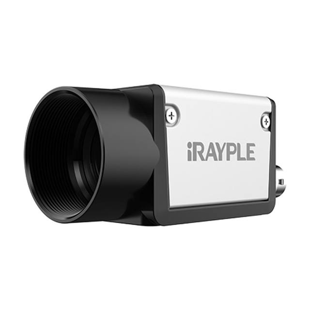
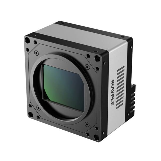
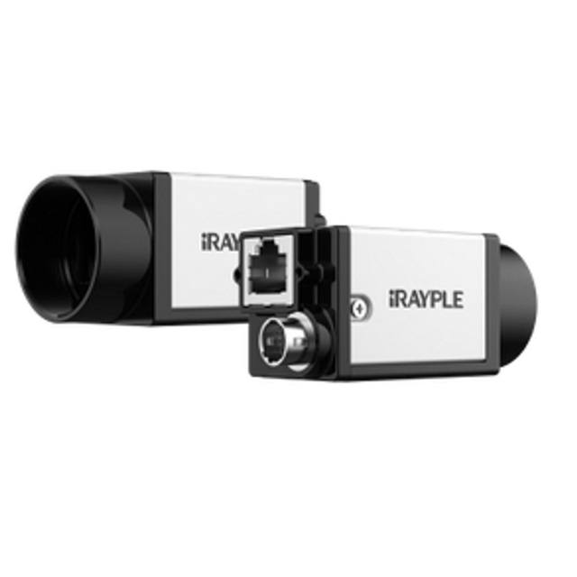
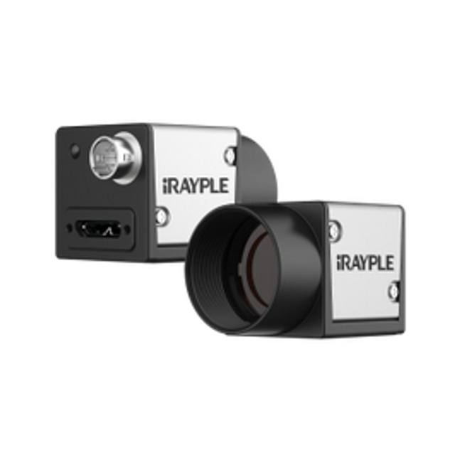
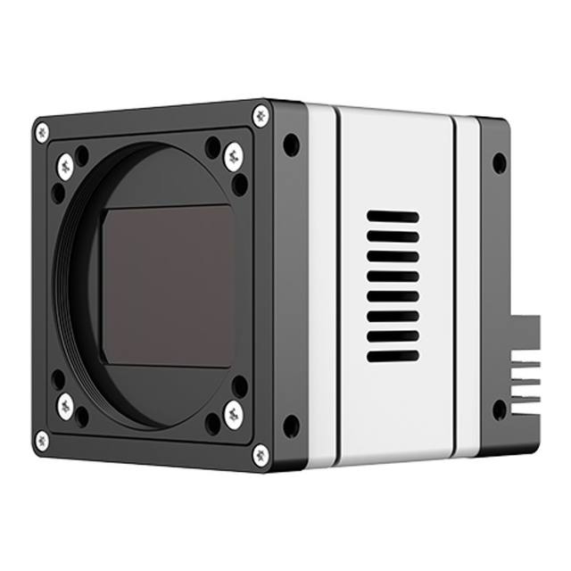
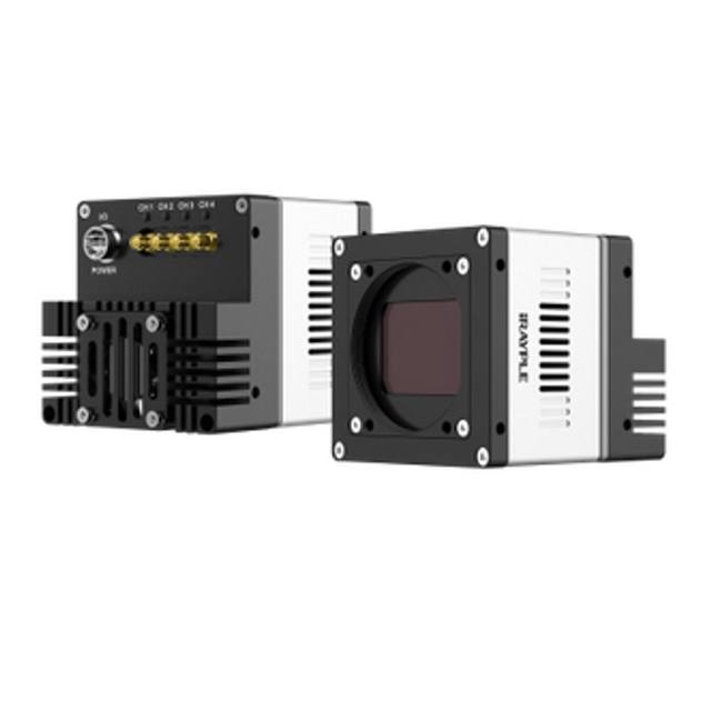
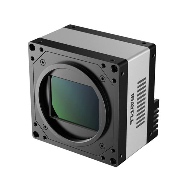
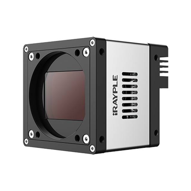
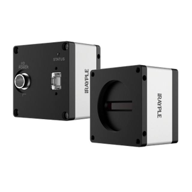
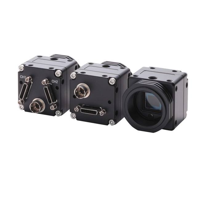
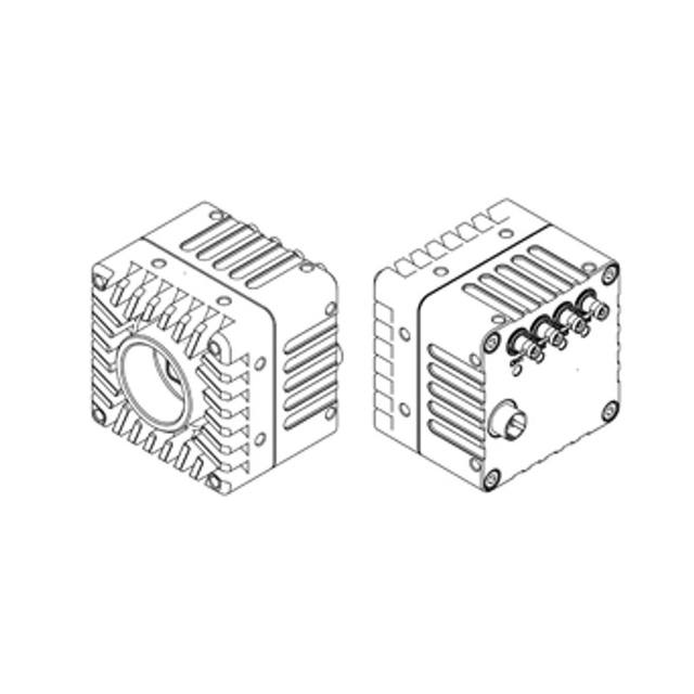
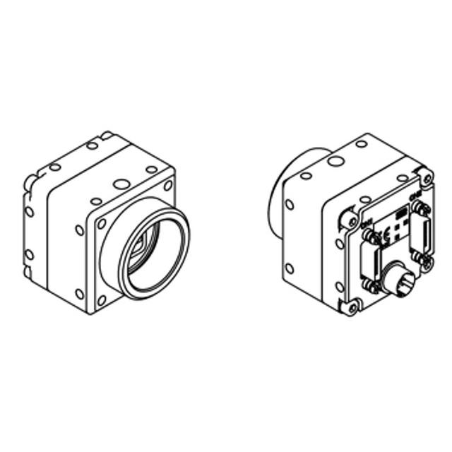
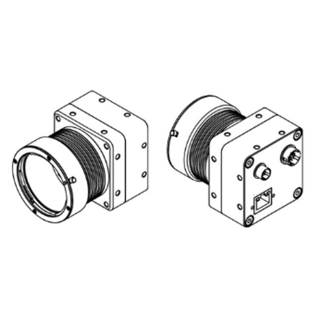
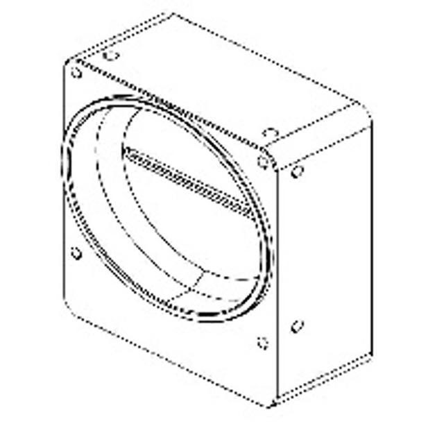
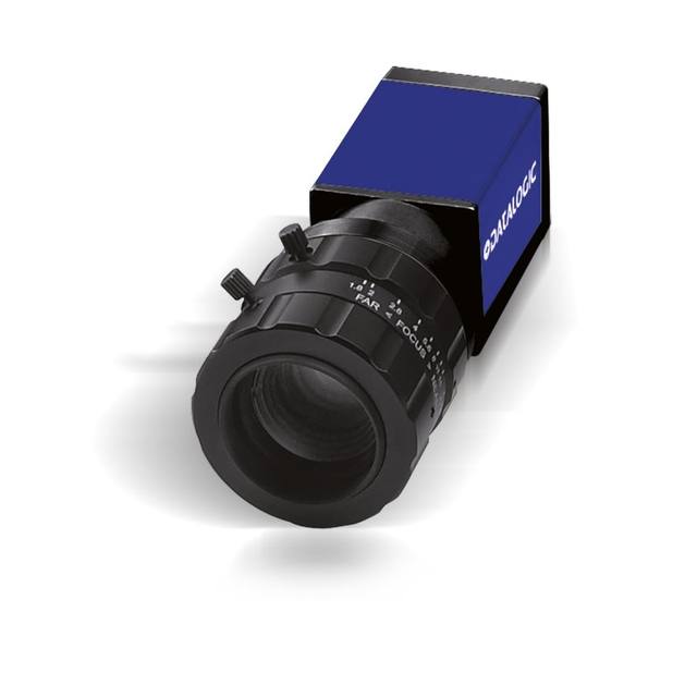
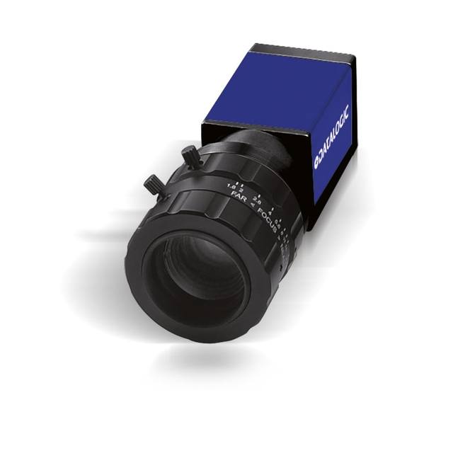
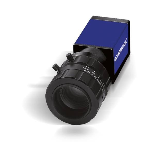
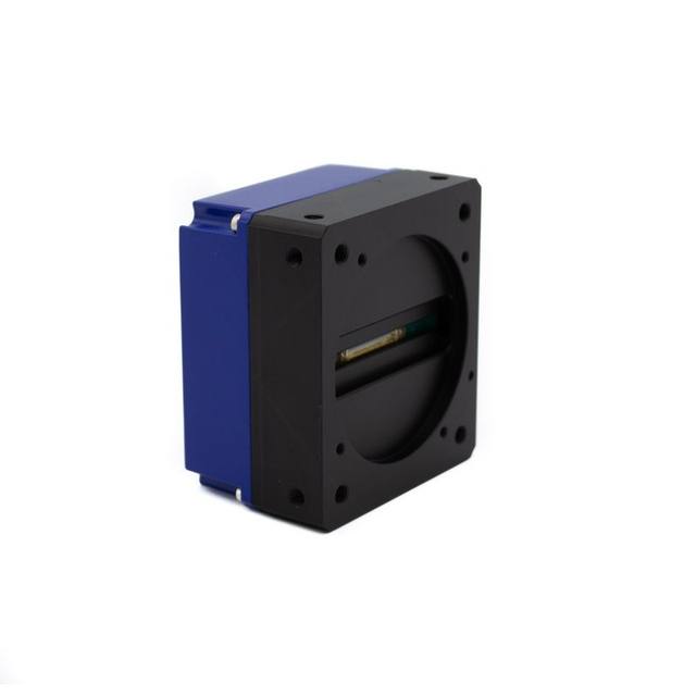
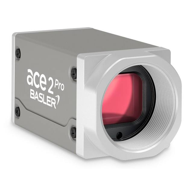
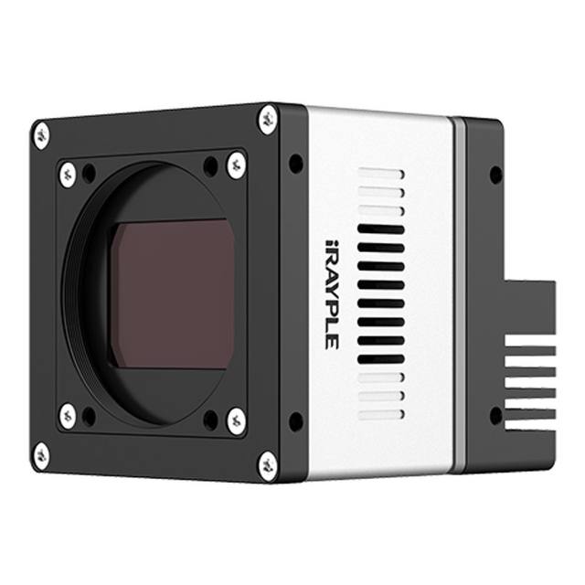
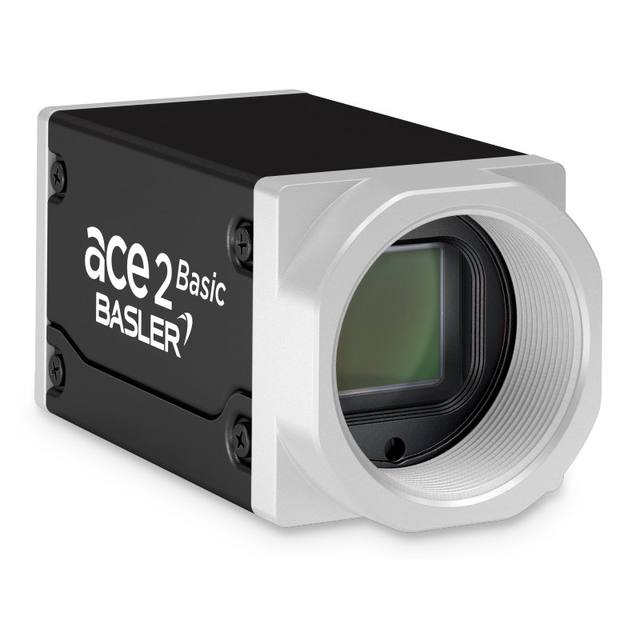
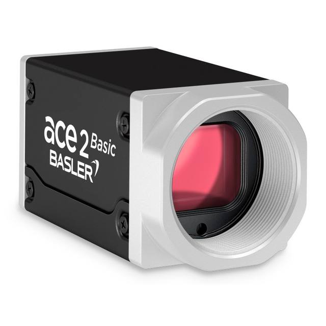
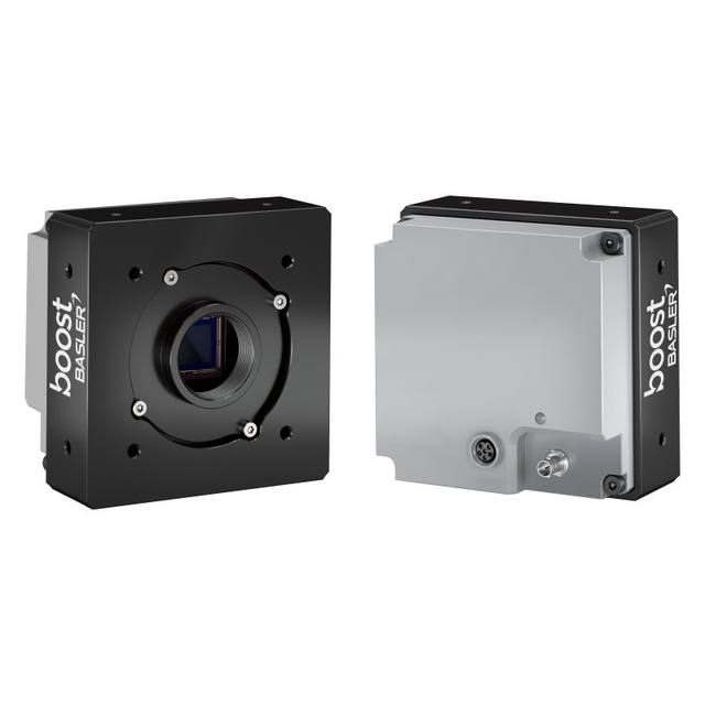
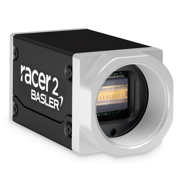
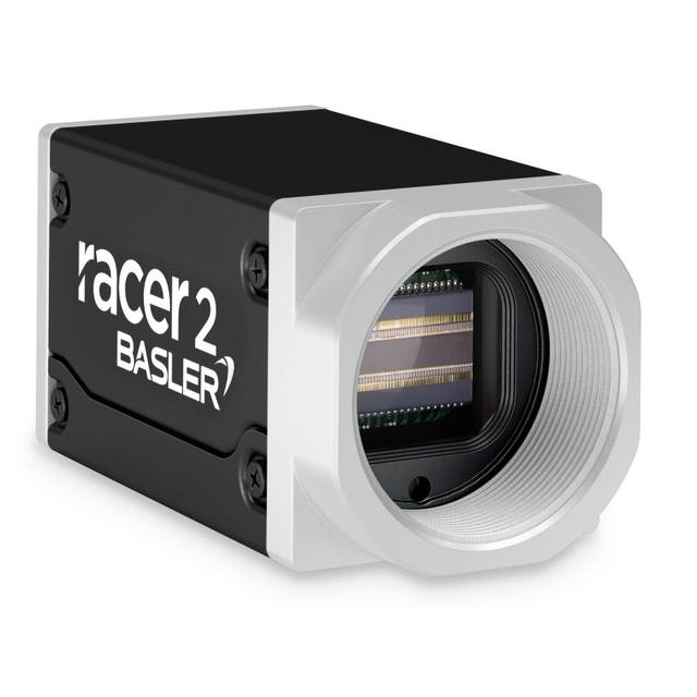
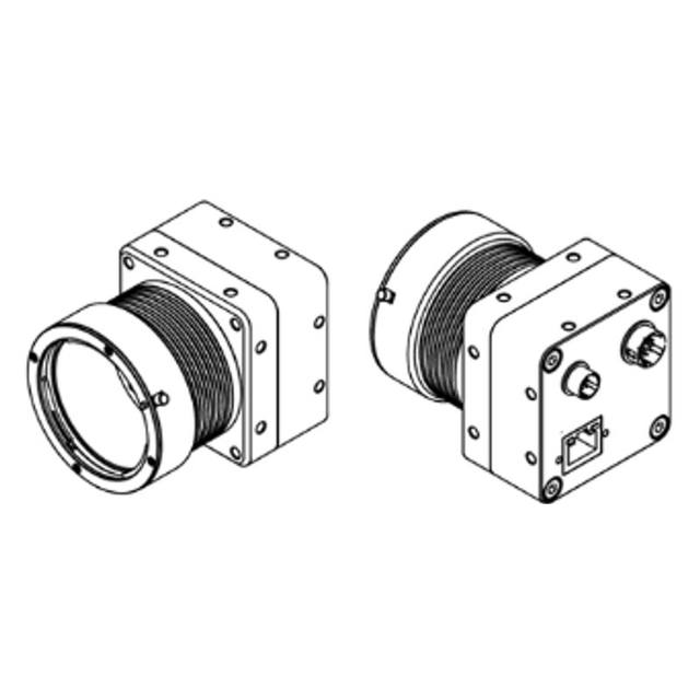
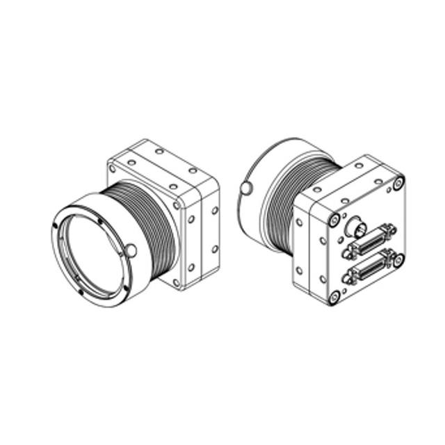
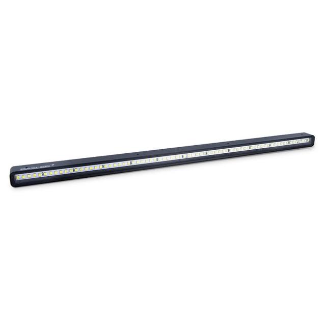
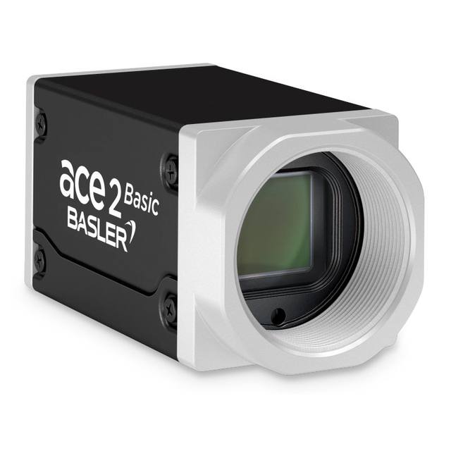
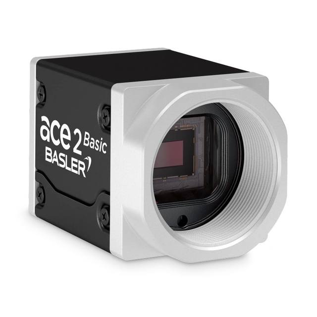
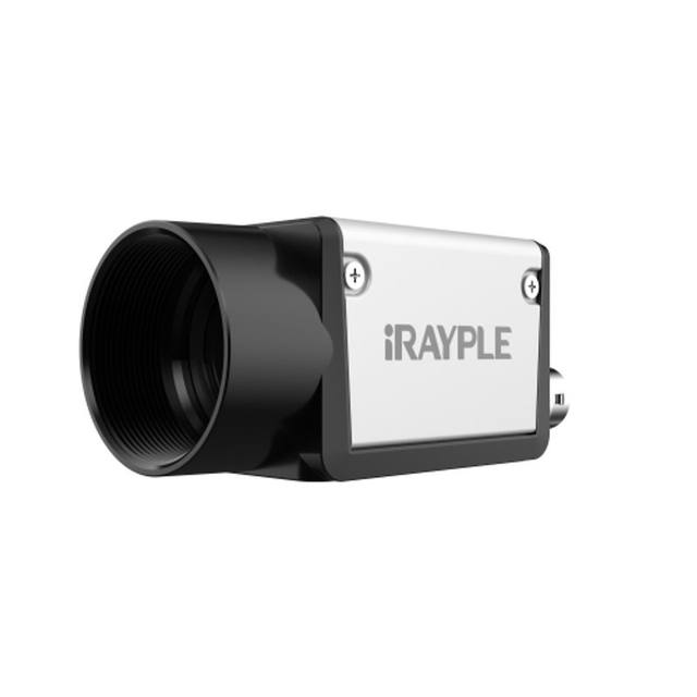
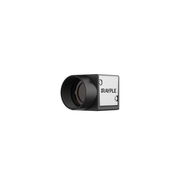
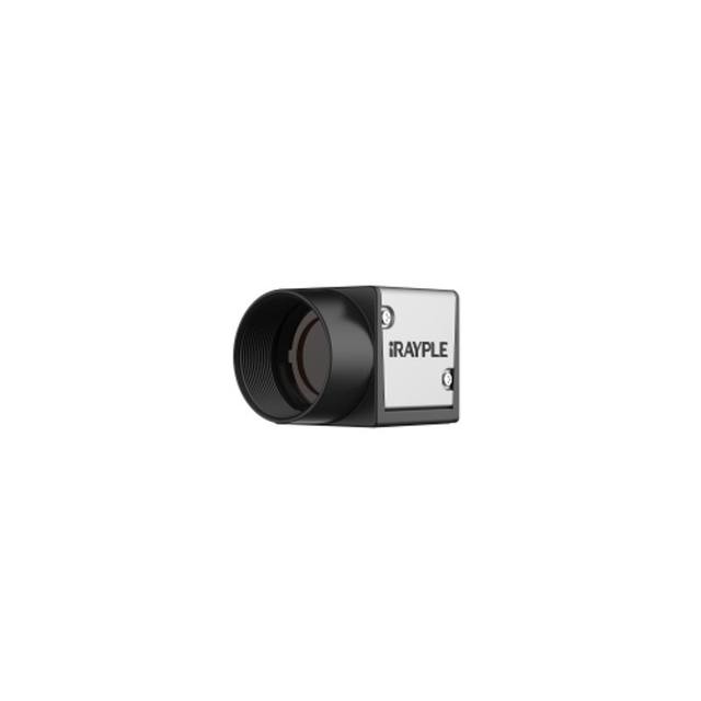
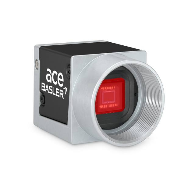
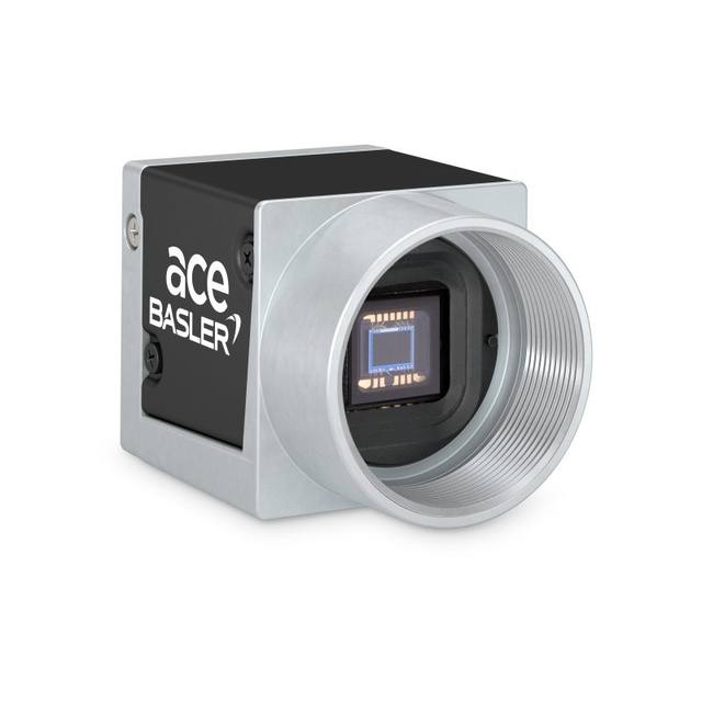
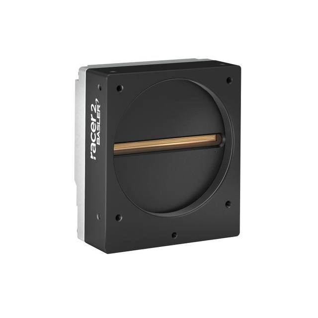
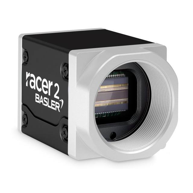
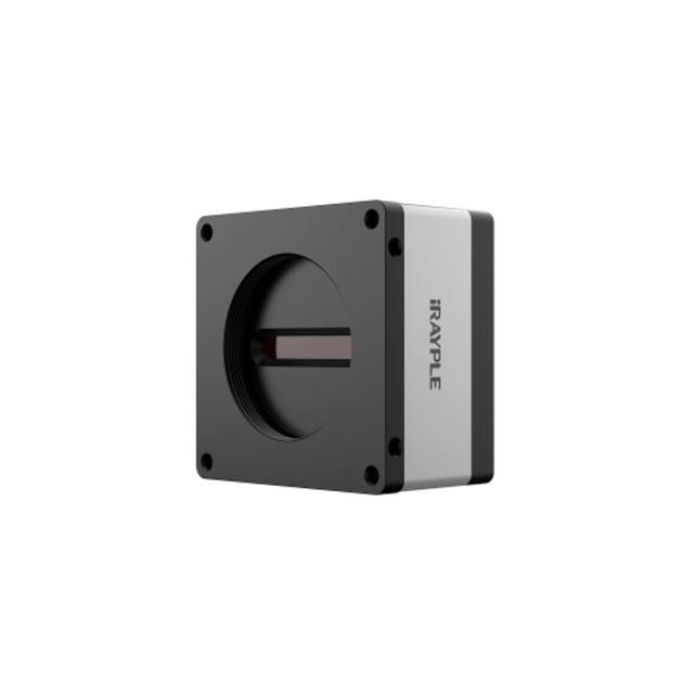
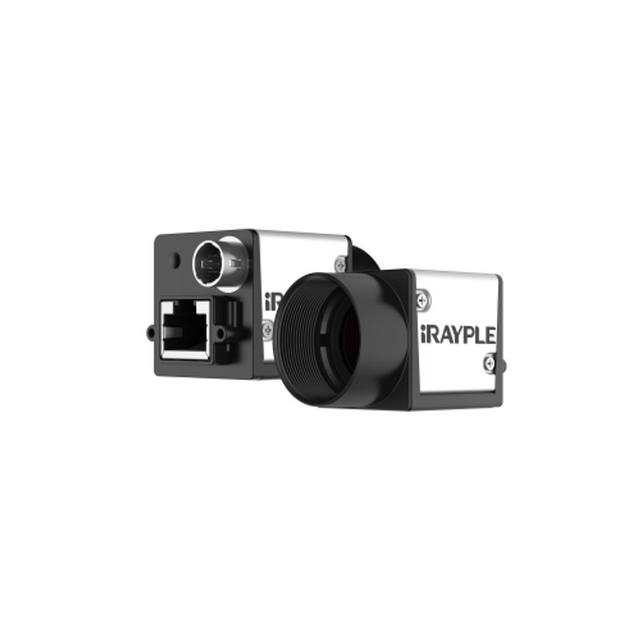
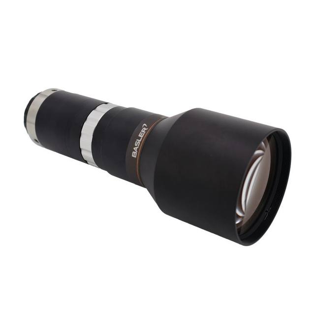
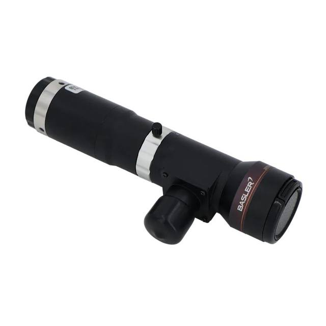
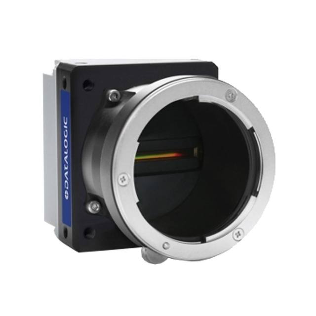
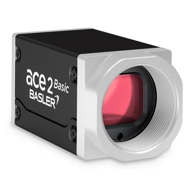
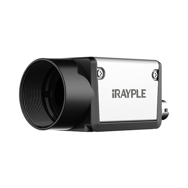
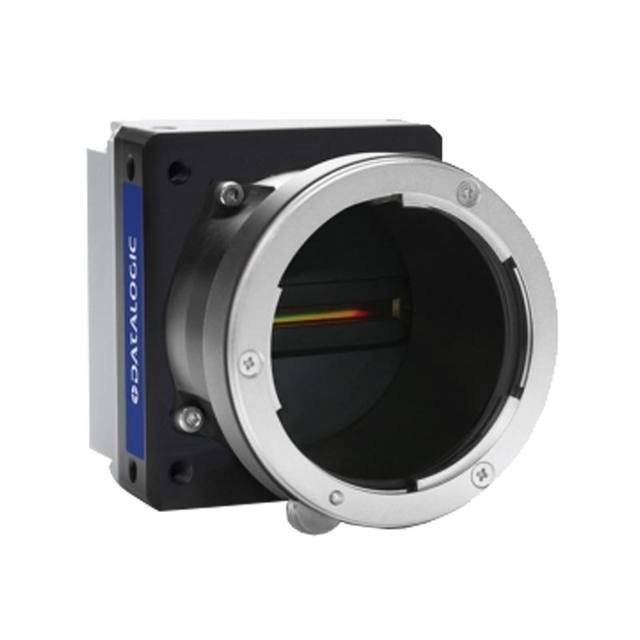
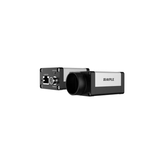
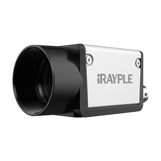
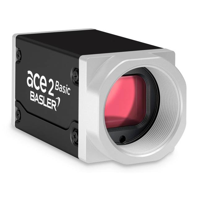
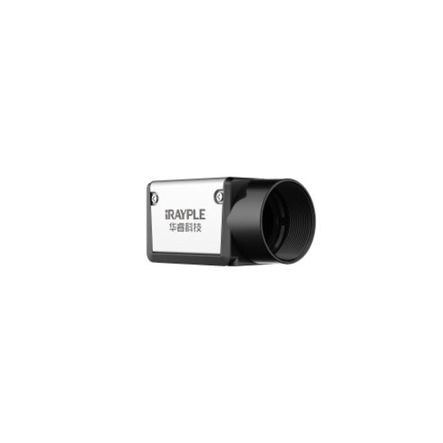
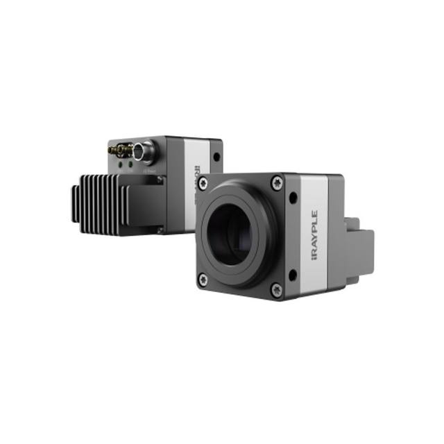
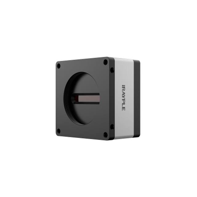
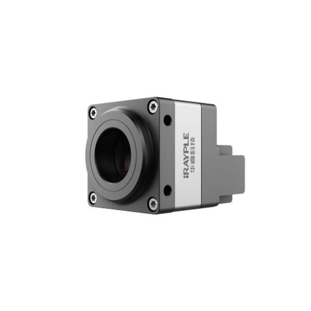
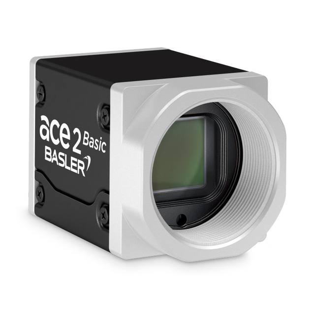
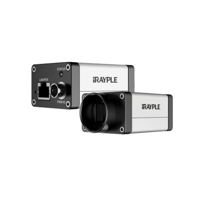
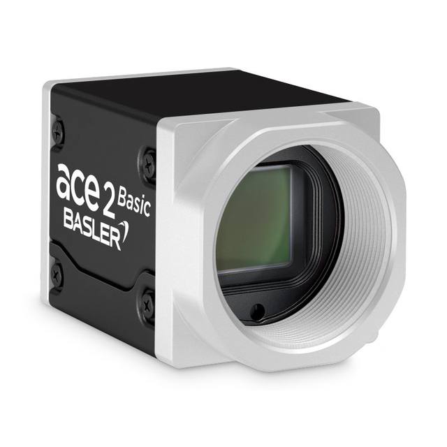
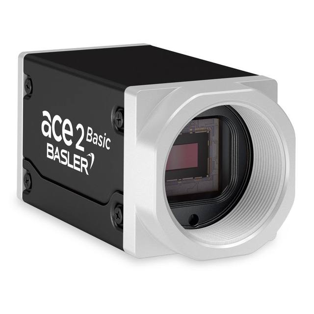
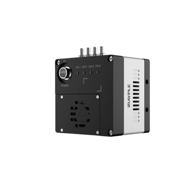
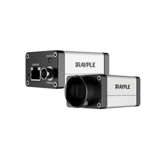
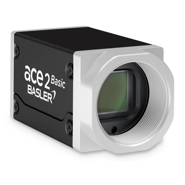
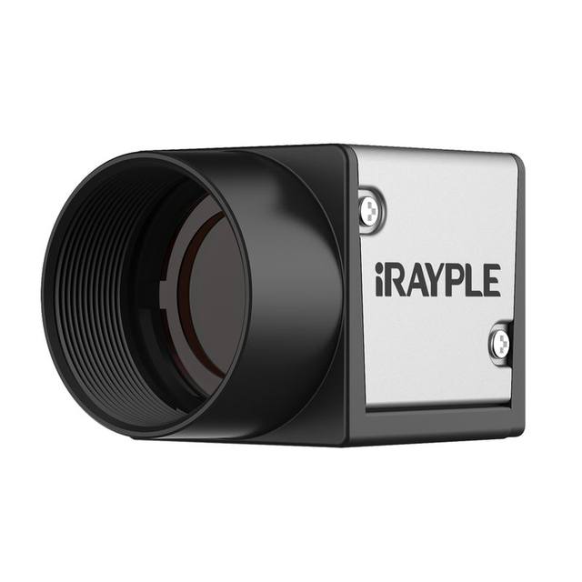
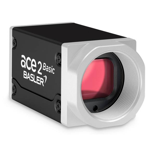
For continuous webs, sheets, coils, extrusions, foils and any part moving on a conveyor, line scan cameras are usually the right architecture. A line scan camera builds the image one pixel-row at a time as the material passes, synchronised to motion with an encoder, producing a seamless image of effectively unlimited length with very high cross-web resolution. This suits surface inspection well because grazing illumination only needs to be uniform along a single line rather than across a whole 2D field, which is far easier and more efficient to engineer, and because the geometry between light, surface and sensor stays constant for every line. Line scan is the standard choice for wide-web and high-throughput surface inspection, and the catalog includes GigE and high-line-rate options from Basler and iRAYPLE suited to this role.
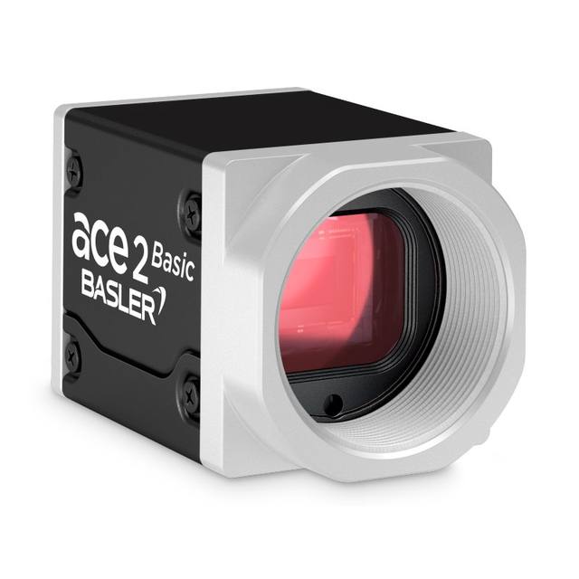
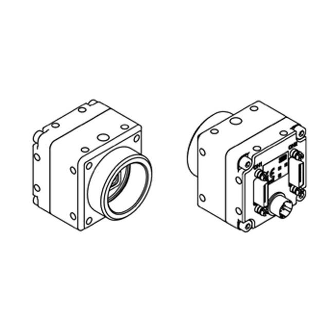
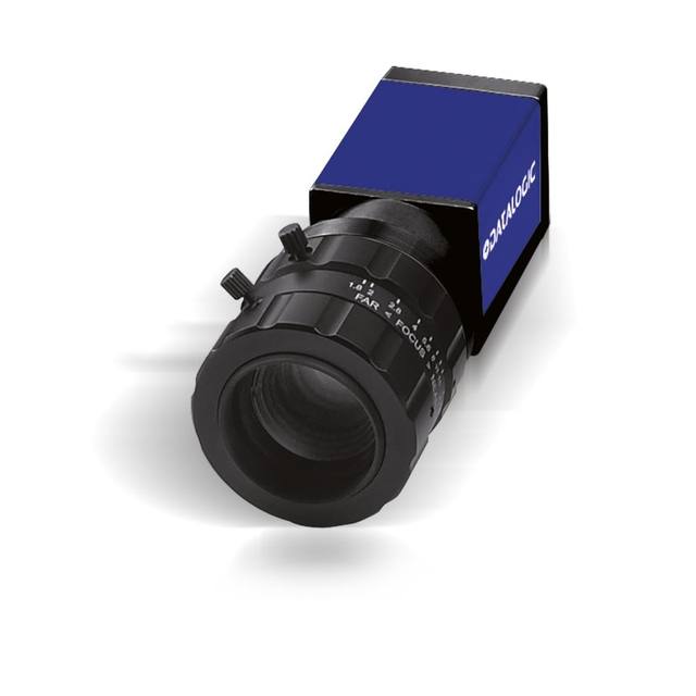
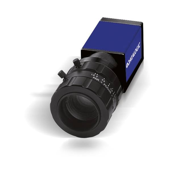
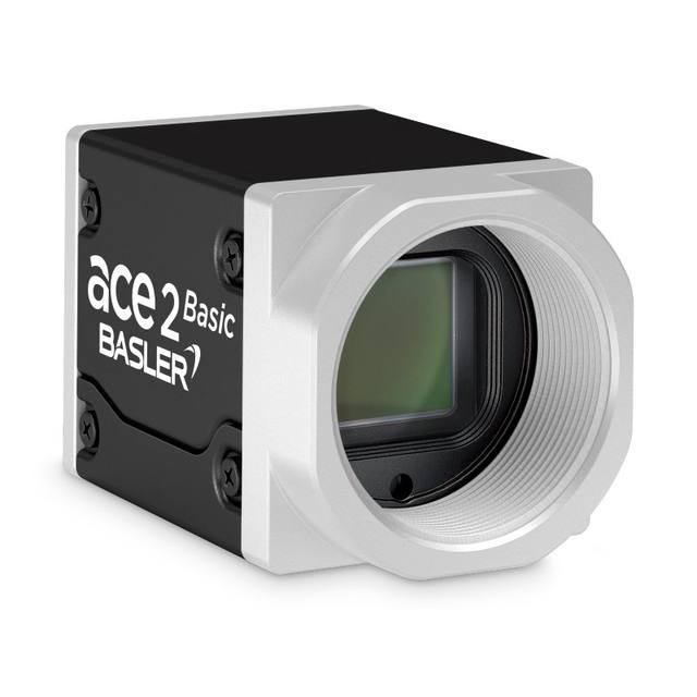
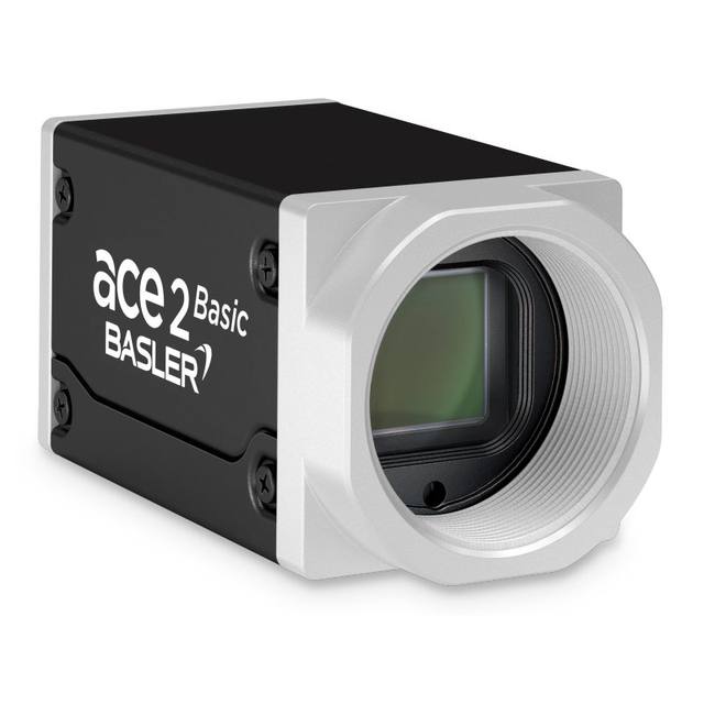
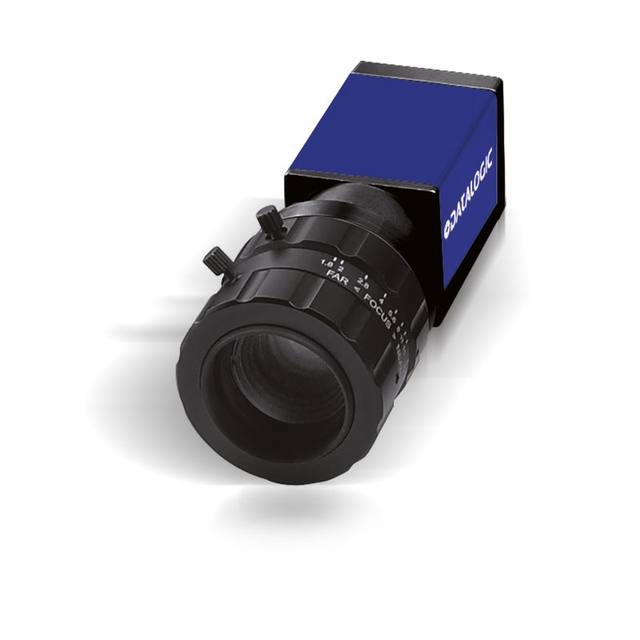
Where parts are discrete, presented station-by-station, or where the surface is curved enough that it must be imaged from several viewpoints, area scan cameras can be the better fit, often combined with multiple shots under different lighting directions. The decision between line scan and area scan comes down to part geometry, motion and how the defect contrast is generated, and it is worth resolving early because it drives the lighting, optics and motion control.
High-speed imaging becomes a hard requirement once the line moves quickly or the defects are small. Two figures dominate: the line rate (for line scan) or frame rate (for area scan) needed to keep pixel resolution along the direction of travel, and the exposure time short enough to freeze motion without blur. Both push you toward sensors with high readout speed, fast interfaces such as GigE, USB3 Vision or CoaXPress, and global-shutter behaviour so that fast-moving features are not geometrically distorted. They also push the lighting harder, because shorter exposures demand more instantaneous light, reinforcing the need for high-output dark-field illumination.
From contrast to a reliable accept/reject decision
Once the optics deliver a high-contrast image, the detection step is comparatively straightforward for well-defined, consistent defects: thresholding, blob analysis, edge and texture metrics on the dark-field image will reliably flag scratches and dents against the suppressed background. This rule-based path is fast, deterministic and easy to validate, and it is the right tool when the defect signature is stable and the surface is uniform.
Many real surfaces are not that cooperative. Cosmetic and aesthetic defects on textured, brushed, grained or naturally variable materials are notoriously hard to separate from acceptable surface variation with fixed rules, because the boundary between cosmetic noise and a genuine reject is subjective and context-dependent. This is where a deep-learning approach earns its place: trained on labelled examples, an anomaly or defect model learns the normal appearance of the surface and flags meaningful deviations, tolerating natural variation that would trip a hard threshold. Rosepetal, the group's deep-learning inspection software, is built for exactly this class of problem and can run on the same line scan or high-speed images, so AI is added only where it genuinely outperforms classical vision rather than by default.
Whichever method you choose, the imaging chain is the foundation. Neither a classical algorithm nor a neural network can recover a defect that the lighting and camera never made visible, which is why the engineering effort concentrates on optics and acquisition first.