iRAYPLE A9B57 Series — 25MP CXP-6 Large Area Scan (Mono/Color)
A9B57MX703E
The A9B57 series is part of iRAYPLE's AX Large Area Scan lineup, built around the 1.1-inch Gpixel GMAX0505 sensor at 5120×5120 resolution with 2.5 µm pixel pitch and a global shutter. Six confirmed variants cover two CXP-6 channel configurations: the compact 2-channel 703 models (MX703E mono 42 fps, CX703E color 41.8 fps) in a C-mount body at ~7.5 W, and the higher-bandwidth 4-channel 200/250 models achieving 90 fps at ~13 W with C-mount (200) or M58×0.75 (250) optics. All models conform to CoaXPress and GenICam standards, support PoCXP and DC 24 V power, feature pixel-by-pixel FFC, 3 opto-isolated I/Os and 1 RS-232 port, and are designed for high-precision inspection in semiconductor, FPD, battery, and photovoltaic industries.
Brand
iRAYPLE
Camera type
Area Scan
Interface
CoaXPress CXP-6 (2×6.25 Gbps on 703 models; 4×6.25 Gbps on 200/250 models)
Resolution
26.2 MP (5120 × 5120); marketed as 26 MP by iRAYPLE
The iRAYPLE A9B57 series is built around Gpixel's GMAX0505, a 1.1-inch global-shutter CMOS sensor delivering a square 5120 × 5120 pixel array — 26.2 MP effective, marketed by iRAYPLE as 25 MP — with a 2.5 µm pixel pitch. The global shutter is the defining characteristic for any installer working with moving substrates: every pixel integrates simultaneously, so there is no row-skew distortion when a panel, wafer, or battery cell travels under the camera at speed. At 2.5 µm, the pixel pitch is fine enough to resolve sub-pixel features in dimensional measurement and surface-anomaly detection, but it does demand careful lens selection: at the sensor's Nyquist frequency lens MTF and illumination intensity become real constraints, and exposure times must be kept short to avoid motion blur on the object side.
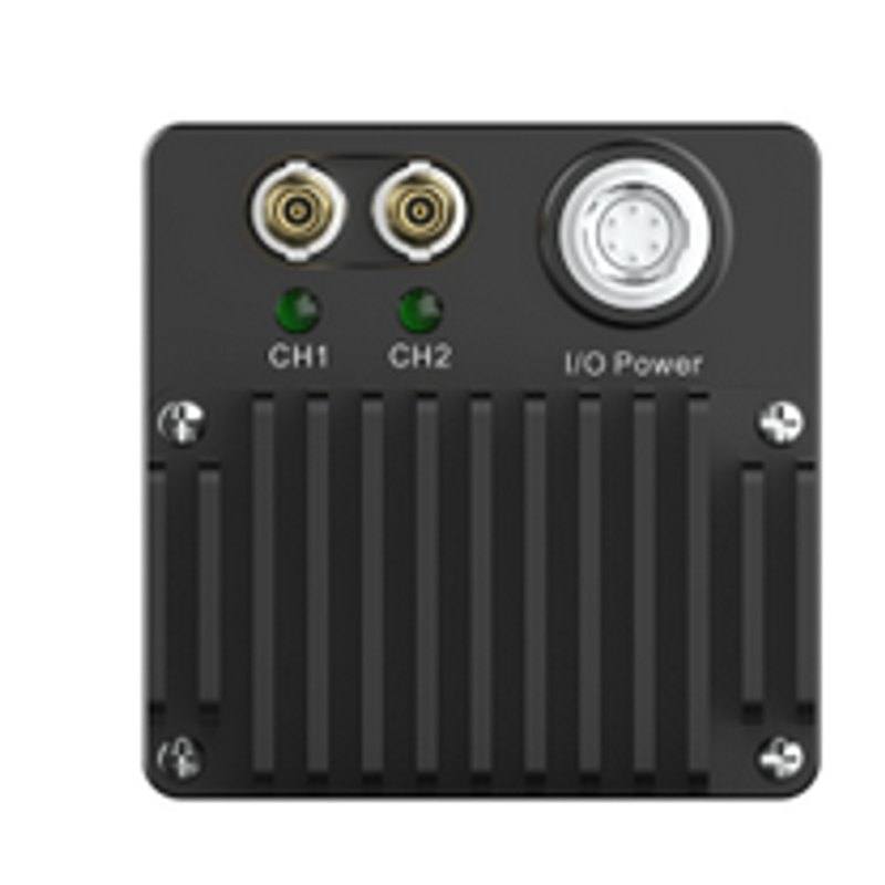
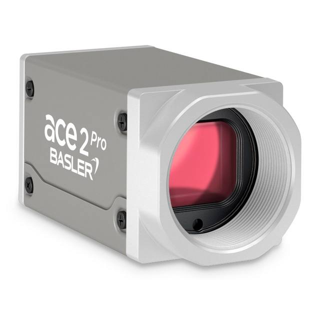
The family splits into two CXP-6 bandwidth tiers that directly govern frame rate and power budget. The 703 variants (MX703E mono, CX703E color) use a 2-channel CXP-6 link — 2 × 6.25 Gbps — producing 42 fps (mono) or 41.8 fps (color) at full resolution from a C-mount body consuming approximately 7.5 W. The 200 and 250 variants double the link to 4 × 6.25 Gbps, reaching 90 fps at full resolution at approximately 13 W; the 200 variant retains C-mount while the 250 variant adopts an M58 × 0.75 thread to accommodate the larger image circles required by high-grade macro and telecentric lenses designed for 1-inch-plus sensors. All variants draw DC 24 V through a 12-pin Hirose connector or via PoCXP directly from the coax cable, which simplifies wiring in tight integrations. The 50 × 50 × 45 mm body at 240 g fits into gantry arms and multi-camera bar fixtures without driving mechanical redesigns.
Every model in the series implements pixel-by-pixel flat-field correction (FFC), three opto-isolated I/O lines, and one RS-232 port, and conforms to both CoaXPress and GenICam standards. FFC is critical with a 2.5 µm pixel pitch on a 1.1-inch die: even modest sensor shading and lens vignetting translate into grey-level gradients that can produce false-positive defect calls at the sub-percent contrast levels typical of semiconductor, FPD, battery, and photovoltaic inspection. The opto-isolated I/Os support hardware trigger synchronisation to encoders, PLC outputs, or external strobe controllers, enabling flash-duration-limited exposures that maximise SNR without raising continuous power. GenICam compliance means the camera enumerates correctly in standard frame grabbers and vision SDKs without vendor-specific drivers, reducing integration time on new line deployments.
Best for
Large-panel flat display (FPD) and semiconductor wafer inspection where the square 5120 × 5120 array covers wide substrates in fewer imaging stations than rectangular sensors, reducing both hardware cost and cycle time.
Battery cell and electrode surface inspection requiring global shutter to image continuous-feed foil or wound cells in motion without geometric distortion, with pixel-level FFC eliminating shading artefacts that would obscure coating defects.
High-throughput dimensional gauging of electronic components or precision-machined parts where the 90 fps capability of the 200/250 models supports fast conveyor speeds, and the 2.5 µm pixel pitch provides the fine spatial sampling needed for sub-pixel edge localisation.
Photovoltaic cell and module inspection, where the large square field of view maps naturally to standard cell formats and the CXP-6 bandwidth sustains continuous acquisition during scan-and-capture sequences over full-module lengths.
Multi-camera 2D surface coverage rigs in automotive or electronics final inspection, where GenICam compliance and PoCXP simplify the integration of several cameras on a single frame grabber card with minimal discrete power wiring.
Selection notes
Choose the 703 variants (2-channel CXP-6, 42 fps mono / 41.8 fps color) when your cycle time budget tolerates sub-50 fps and you want to minimise power draw (~7.5 W) and frame-grabber channel count. Upgrade to the 200/250 variants (4-channel CXP-6, 90 fps) when throughput or short-exposure motion-freeze requirements demand it — but budget for a 4-channel port or second 2-channel port on the frame grabber.
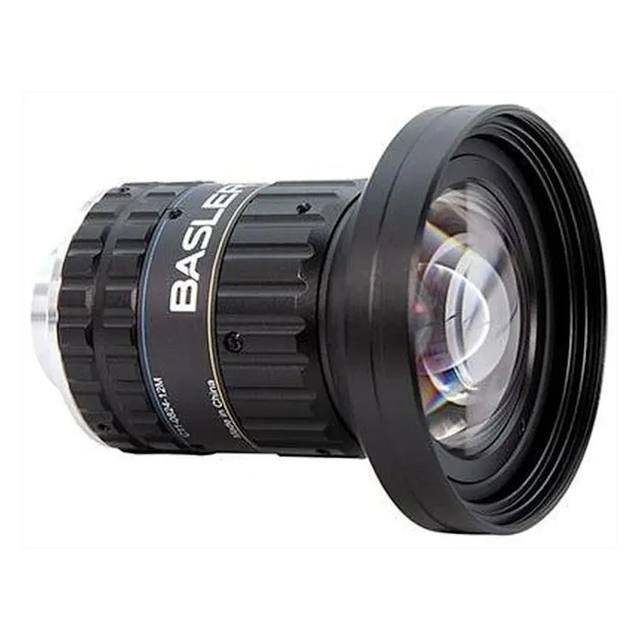
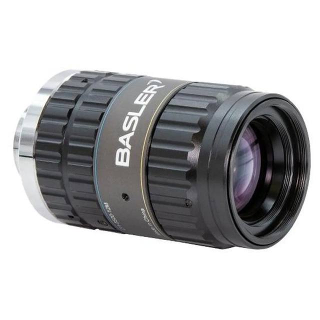
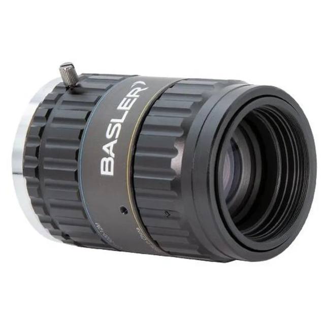
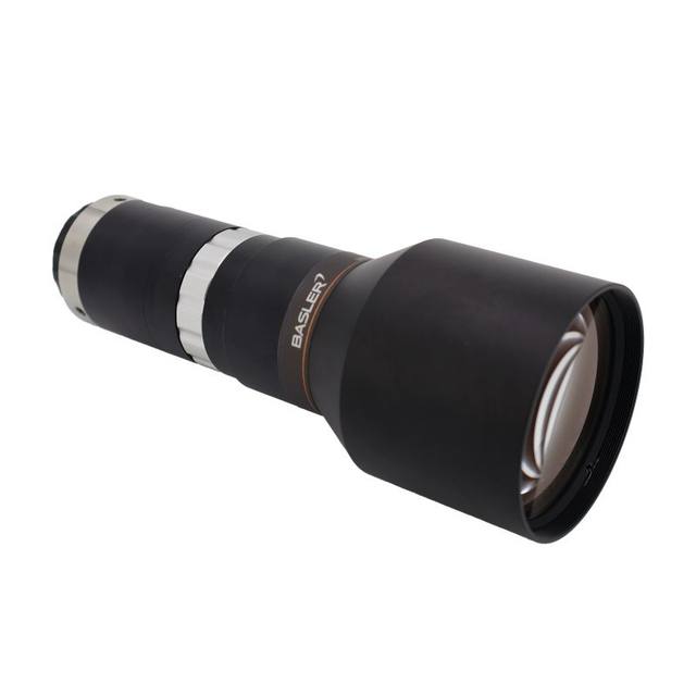
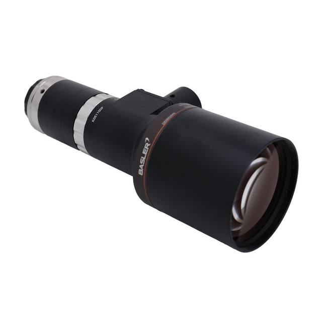
Lens mount selection is non-trivial: the C-mount variants (703 and 200) accept standard industrial C-mount optics, but at 1.1-inch format the image circle requirement eliminates most compact C-mount lenses — verify the lens image circle covers the full 5120 × 5120 diagonal (~18.1 mm). The M58 × 0.75 mount on the 250 variant opens access to large-format telecentric and macro lenses designed specifically for sensors of this size, which is the preferred path for dimensional gauging applications.
PoCXP simplifies cabling in multi-camera fixtures but verify that the frame grabber's PoCXP power budget covers the ~13 W draw of the 4-channel 200/250 variants; some grabber channels are rated for 2-channel camera loads only. DC 24 V via the 12-pin Hirose is the safe fallback for high-power configurations.
The operating temperature range of -30 °C to +50 °C supports deployment in most industrial environments, including pharma lines that may see low ambient temperatures, but the tight 2.5 µm pitch makes the camera sensitive to thermally induced focus drift — factor mechanical thermal stability into the mount design if the installation sees rapid ambient swings.
For surface inspection relying on dark-field or structured illumination, keep working apertures in a mid-range to avoid diffraction limiting the effective resolution at the sensor's Nyquist frequency; verify lens MTF at the Nyquist frequency before finalising the optical train.
Specifications: General
Brand
iRAYPLE
Camera type
Area Scan
Specifications: Sensor
Resolution
26.2 MP (5120 × 5120); marketed as 26 MP by iRAYPLE
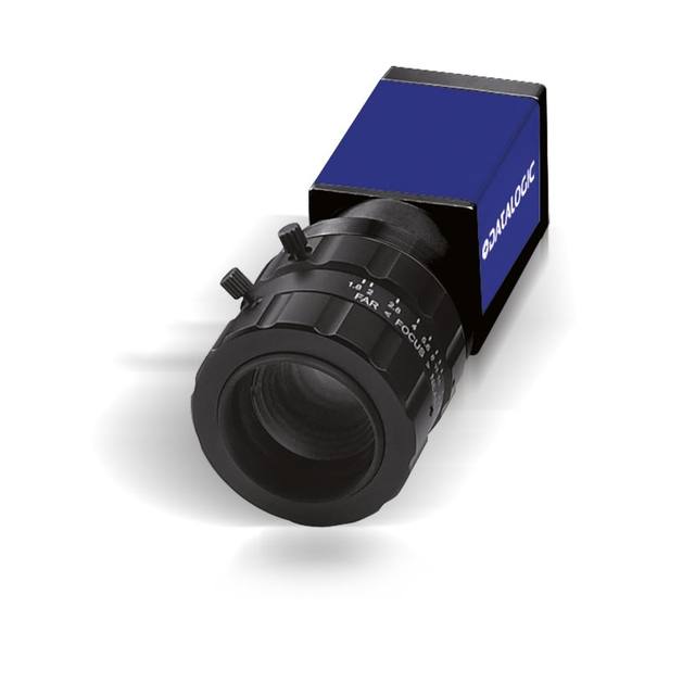
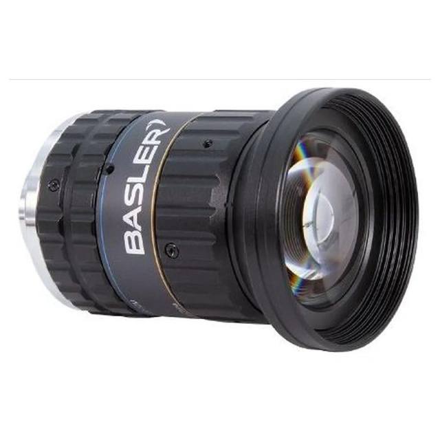
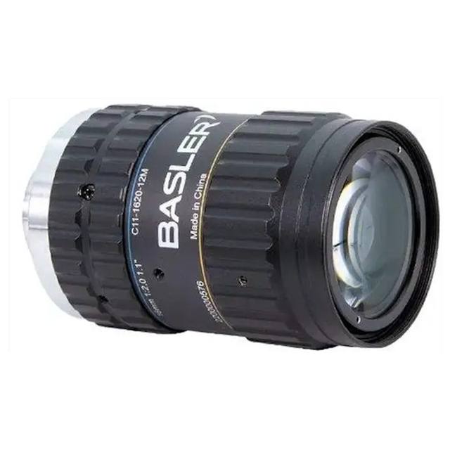
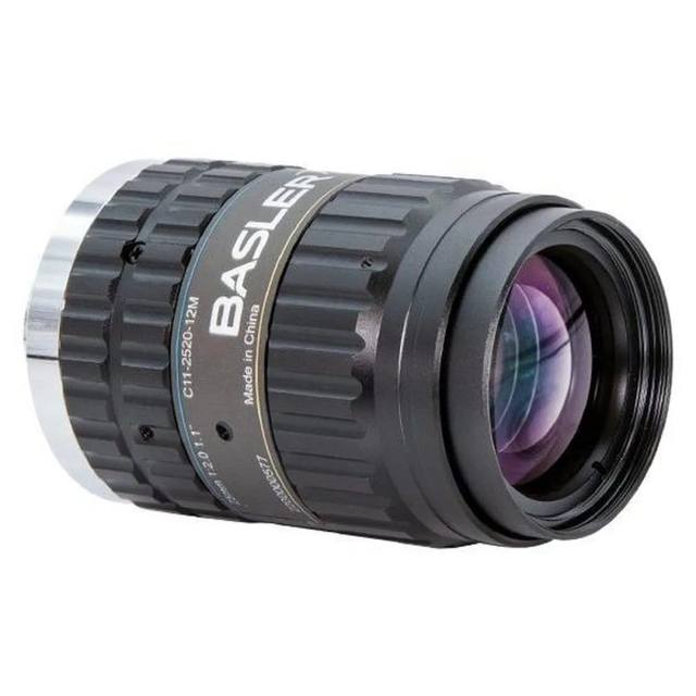
Matched automatically by: lens mount fits the camera mount · lens image circle covers the camera sensor — this camera: C-mount (703/200 variants); M58×0.75 (250 variant) · 1.1" CMOS sensor.
By category
All 67C-mount lenses 43Telecentric lenses 24
By brand
All 67Basler 34iRAYPLE 23Omron / Sentech 8Datalogic / Datasensing 2
Follow these steps to bring up your iRAYPLE camera, capture a first image, and move from the viewer to your own application. The flow is the same across the A, AE, AX and L series; only the physical interface differs.
Download and install the iRAYPLE machine-vision SDK together with its viewer client for your operating system. The installer provides the camera drivers, the GenTL producer, and the viewer you will use for first light. For GigE Vision models, also install or enable the bundled filter/performance driver on the network adapter to maximize throughput.
2. Connect the camera to the correct interface
Wire the camera to its matching host interface: a dedicated Gigabit (or 10 GigE) NIC for GigE Vision models, a USB3 Vision port with a quality cable for USB3 models, or a frame grabber for CoaXPress models. Power the camera (PoE, USB bus power, or PoCXP / external supply as applicable). For GigE Vision, put the NIC and camera on the same subnet and, where supported, enable jumbo frames.
3. Detect and open the camera in the viewer
Launch the iRAYPLE viewer, run device enumeration, and select your camera from the discovered list. Open it to load the device feature tree (GenICam node map). If a GigE camera is found but cannot be opened, correct the IP configuration so the camera and NIC are in the same address range.
4. Set exposure, gain and trigger, then grab a first image
Start with continuous (free-run) acquisition under stable lighting. Adjust exposure time and gain for a well-exposed, low-noise image, set the pixel format (e.g. Mono8 or a Bayer/RGB format), and tune white balance on color models. Once the live image looks correct, switch trigger mode to hardware or software trigger to synchronize capture with your process, and verify a single triggered frame.
5. Move from the viewer to the SDK or a GenICam library
With imaging confirmed, reproduce the same settings in code using the SDK's C/C++ or Python API: enumerate, open, configure the relevant GenICam features, register a frame callback or grab loop, and convert frames to your pipeline's buffer format. Since the cameras are GenICam/GenTL-compliant, you can alternatively drive them from a third-party GenICam vision library. From here a stable image stream can feed a deep-learning inspection step such as Rosepetal for automated quality control.
Frequently asked questions
The 703 models use a 2-channel CXP-6 link (2 × 6.25 Gbps), so they occupy two coax ports on a standard CXP frame grabber. The 200 and 250 models use a 4-channel CXP-6 link and therefore require four ports — typically a full quad-channel grabber or two dual-channel ports. Confirm PoCXP power delivery per port if you intend to avoid separate DC 24 V wiring.
The global shutter eliminates row-skew distortion regardless of exposure method, but motion blur during the exposure window is governed by exposure time and conveyor speed, not shutter type. At typical surface-inspection line speeds you will almost certainly need a short strobe pulse or high-intensity continuous illumination to freeze the image. The three opto-isolated I/Os allow hardware trigger synchronisation to a strobe controller.
If your application uses standard industrial C-mount lenses and you have confirmed the lens image circle covers the full 5120 × 5120 sensor diagonal (~18.1 mm), the C-mount variants work. For dimensional gauging with telecentric lenses or any lens designed for sensors larger than 1 inch, the M58 × 0.75 250 variant is the appropriate choice, as most high-quality large-format telecentric and macro optics use M58 or larger threads.
Flat-field correction compensates for spatially non-uniform sensor response and lens vignetting on a per-pixel basis. At 2.5 µm pixel pitch over a 1.1-inch die, even modest vignetting or sensor non-uniformity translates into grey-level gradients that can produce false-positive defect calls in low-contrast surface inspection. For semiconductor, FPD, battery, and photovoltaic inspection — the primary target sectors for this camera — FFC is effectively mandatory and its inclusion in all variants is a significant practical benefit.
The MX (mono) and CX (color) variants share the same sensor format, interface, mechanical envelope (50 × 50 × 45 mm), and weight (240 g), so they are mechanically interchangeable in a fixture. The key difference is that the color variants debayer the raw Bayer output, which slightly reduces the effective spatial resolution and introduces a small frame-rate difference (41.8 fps vs 42 fps on the 703 tier). For pure defect detection and dimensional measurement, mono is generally preferred; color is appropriate where chromatic feature discrimination — solder paste colour, coating contrast — adds inspection value.