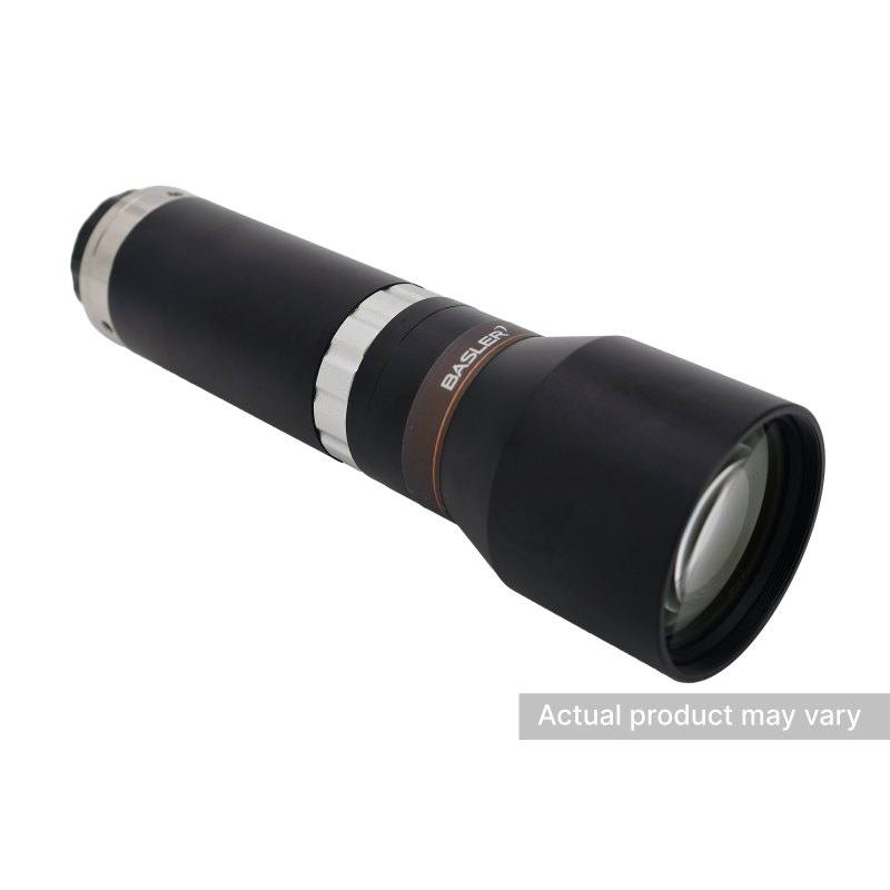
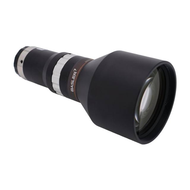
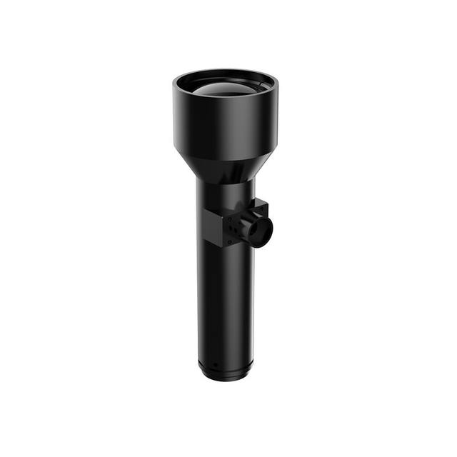
The Basler Lens C11T-08-110-VI is a single-sided telecentric lens engineered for high-resolution dimensional measurement on large sensor formats up to 1.1". It provides a fixed 0.8x magnification at a nominal 110 mm working distance (±2 mm tolerance) with a fixed aperture of F6.6. The lens achieves a maximum distortion of 0.08% and object-side telecentricity of 0.06°, providing excellent geometric fidelity across an 18 mm image circle. At F6.6, the theoretical object-side resolution is 4.9 µm and MTF30 is 128 lp/mm, with a depth of field of ±0.4 mm.
The Basler C11T-08-110-VI is a single-sided object-side telecentric lens with a fixed 0.8x magnification at a 110 mm working distance (±2 mm tolerance). Unlike conventional entocentric lenses whose apparent magnification shifts as the subject moves closer or farther away, a telecentric design keeps the chief ray parallel to the optical axis on the object side. This means that a feature at 108 mm appears exactly as wide as the same feature at 112 mm — a property essential for any application that measures physical dimensions from image data. The 18 mm image circle covers the full diagonal of a 1.1" sensor, making it the maximum supported sensor format.
The optical performance figures confirm this lens is designed for high-accuracy metrology. Object-side telecentricity of 0.06° directly bounds the parallax-induced measurement error across the full field. Maximum distortion of 0.08% keeps geometric error very low across the image circle before any software correction. Resolving power is rated at a theoretical object-side resolution of 4.9 µm and MTF30 at 128 lp/mm at the working aperture of F6.6. Depth of field at F6.6 is ±0.4 mm, adequate for flat or near-flat workpieces in a controlled, repeatable part-presentation fixture. The lens ships in a C-mount barrel with a variable iris and is compatible with C-mount industrial cameras from any manufacturer.
Best for
Dimensional gauging and go/no-go measurement of small mechanical parts, PCB features, or pharmaceutical tablets where magnification invariance across a ±2 mm depth range is mandatory
High-resolution defect inspection on flat or lightly curved surfaces, particularly when paired with a 1.1" area-scan sensor to maximise spatial sampling within the 18 mm image circle
Semiconductor and electronics inspection tasks such as die placement, solder joint measurement, or connector-pin pitch verification where low distortion (0.08%) and high telecentricity (0.06°) are required
Automotive and medical-device component gauging lines where a fixed 110 mm working distance can be mechanically enforced by a fixture, turning the tight depth-of-field (±0.4 mm) into a feature rather than a limitation
Applications migrating from a conventional entocentric macro lens where perspective error is causing measurement drift across the field and a direct drop-in C-mount replacement with variable iris is needed
Selection notes
Sensor format must not exceed 1.1" (18 mm image circle diagonal). Cameras with sensors whose diagonal exceeds 18 mm will exhibit vignetting and loss of telecentricity at the corners. Confirm the active sensor diagonal of the chosen camera before pairing.
The nominal 110 mm working distance has only a ±2 mm tolerance. Verify that the mechanical envelope of the inspection cell — part-handling tooling, conveyor height, lens barrel length — can place the object plane within that range. The depth of field of ±0.4 mm is a separate, tighter constraint on the flatness of the object itself.
At 0.8x magnification, the pixel pitch of the camera maps directly to object-space resolution: divide the camera's pixel pitch by 0.8 to get the object-side sampling pitch. Compare this against the lens's 4.9 µm theoretical object-side resolution limit to confirm the camera and lens are well-matched and the sensor is not over-sampling beyond what the optics can resolve.
The aperture is F6.6 with a variable iris. For measurement stability, avoid varying the iris between production runs. Exposure should be controlled primarily through illumination intensity or integration time to keep the aperture at its calibrated position.
Distortion of 0.08% is very low but not zero. For sub-pixel measurement accuracy, calibrate the system with a traceable dot-grid target after mechanical installation to remove residual distortion and correct for any sensor tilt, producing a complete homography for pixel-to-millimetre mapping.
Specifications: General
Brand
Basler
Specifications: Optical
Lens mount
C-mount
Magnification
0.8x
Working distance
110 mm (±2 mm)
Aperture (f-number)
F6.6 (variable iris)
Image circle / max sensor
Ø18 mm / 1.1"
Telecentric
Yes (object-side telecentric)
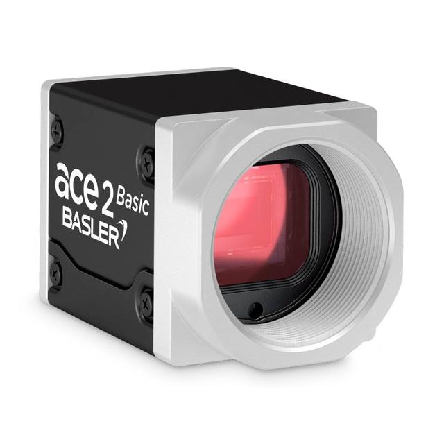
Applications this camera is commonly selected for. Open one to see the full recommended hardware and approach.
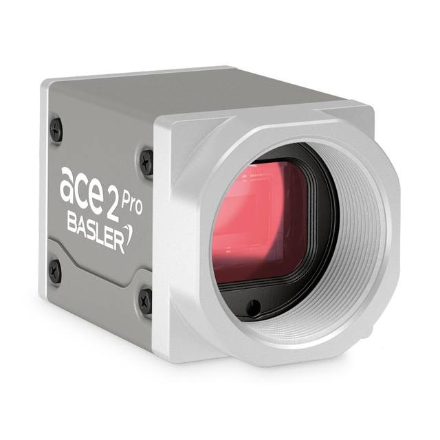
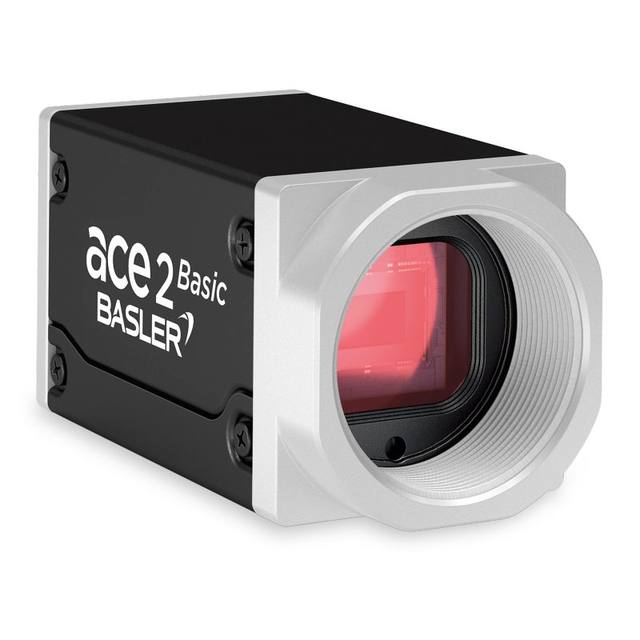
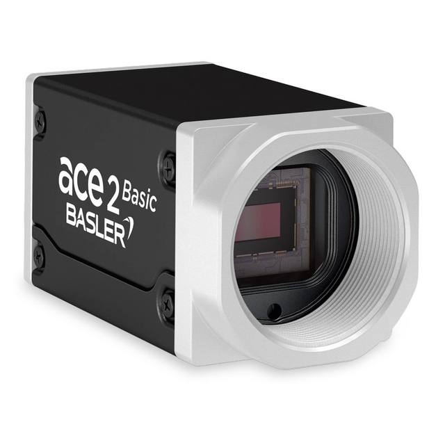
Matched automatically by: camera mount fits the lens mount · camera sensor is covered by the lens image circle — this lens: C-mount · Ø18 mm / 1.1" image circle.
Get a first image quickly with the pylon Viewer, then move into the pylon SDK for your application. These cameras are GenICam/GenTL-compliant, so any compliant vision software can drive them as well.
Download and install the pylon Camera Software Suite for your OS from Basler. This provides the pylon Viewer, the GenTL transport-layer producers and the pylon SDK (C/C++/.NET/Python). On Windows the installer adds the needed drivers; on Linux follow the included setup notes for USB and network permissions.
2. Connect the camera and check the link
Cable the camera to its matching interface: GigE Vision to a GigE port (use a quality cable and, ideally, a dedicated NIC with jumbo frames enabled), USB3 Vision to a USB 3.x port with the supplied cable, or CoaXPress to the frame grabber. Provide power where required (PoE, USB bus power, or PoCXP). Open the pylon Viewer and confirm the camera appears in the device list; for GigE, make sure the camera and NIC are on the same subnet.
3. Grab a first image and set exposure, gain and pixel format
Select the camera in the pylon Viewer and start a continuous grab. Adjust exposure time and gain until the image is well exposed (avoid clipped highlights), set the pixel format (e.g. Mono8 or a Bayer/RGB format), and focus the lens. Use a test pattern if the lens or scene is not ready yet.
4. Configure triggering and acquisition
Decide between free-run and triggered acquisition. For synchronized capture, set the trigger source (software or a hardware line on the I/O connector), trigger mode and any debounce or exposure mode, then verify timing. Note the parameter names you change in the Viewer feature tree, as you will reuse them in code.
5. Move to the SDK or a GenICam-compliant library
Recreate your settings in code with the pylon SDK (C, C++, .NET or Python) to open the device, apply the same features and pull frames into your pipeline; pylon vTools and pylon AI can add processing blocks. Because the cameras are GenICam/GenTL standard, third-party vision libraries work too. Once the image stream is stable, you can route frames to a deep-learning inspection such as Rosepetal for automated defect detection.
Frequently asked questions
The lens has an 18 mm image circle, which covers sensors up to the 1.1" format. Any sensor whose active area diagonal is 18 mm or less is compatible. Sensors with a larger diagonal will experience vignetting and degraded telecentricity toward the corners.
In a telecentric lens the measurement magnification does not change with object depth. A 0.06° telecentricity angle is among the tightest in the class and directly bounds the parallax-induced measurement error across the full field, which is critical when measuring physical dimensions from image data rather than simply detecting defects.
Coaxial diffuse illumination or dome diffuse lighting are the standard pairings for telecentric lenses. Both fill the telecentric aperture cone uniformly and suppress specular glare from polished or metallic surfaces. The specific lighting choice should be validated for the target material and surface finish.
Yes. For dimensional measurement applications the iris should be set to a fixed, repeatable position and left there. Varying the aperture between measurements can shift the optical centre and introduce telecentricity error. Establish the operating aperture (F6.6 is the rated working aperture) during system calibration and do not change it during production.
The depth of field at F6.6 is ±0.4 mm around the nominal 110 mm working distance. This means the object must be presented within a total axial range of 0.8 mm to remain in acceptable focus. Parts with significant height variation across the field may require multiple exposures or a tightly controlled fixture to keep all features within this range.