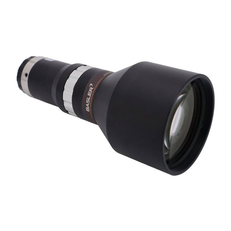
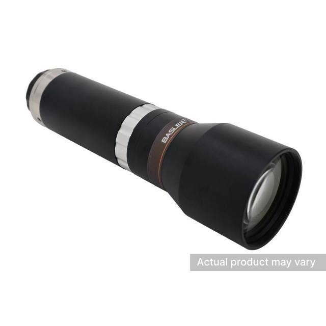
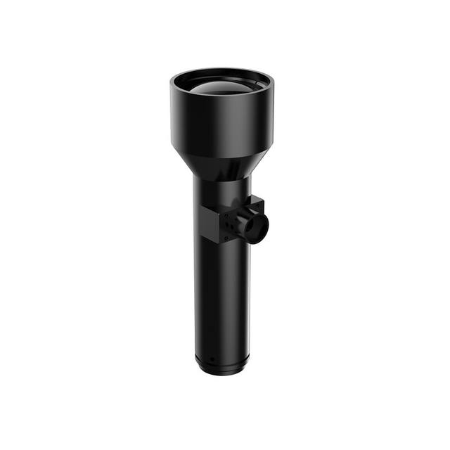
The Basler Lens C23T-03-110-VI is a high-performance, single-sided telecentric lens designed for precision dimensional measurement in machine vision. It delivers 0.3x magnification at a fixed 110 mm working distance with a variable iris ranging from F5.6 to F32. The telecentric design achieves a maximum object-side telecentricity of 0.03° and a maximum distortion of 0.04%, ensuring accurate and consistent measurement regardless of object height variations. Theoretical object-side resolution at F5.6 is 12.5 µm and the depth of field ranges from 5 mm (F5.6) to 28.4 mm (F32).
The Basler C23T-03-110-VI is a single-sided, object-side telecentric lens built specifically for precision dimensional measurement. Unlike conventional lenses that project a perspective image — where object height changes the apparent size of a feature — a telecentric design ensures that the principal ray bundle travels parallel to the optical axis on the object side. The practical consequence is a constant 0.3x magnification at every point within the working volume: an object 5 mm tall and an object 1 mm tall produce the same magnification as long as they lie within the ±14.2 mm depth-of-field band available at F32. Telecentricity error is specified at a maximum of 0.03°, ensuring that height variation within the working depth of field produces no meaningful change in apparent object size — eliminating the need for height-correction software in most gauging applications.
Optical performance is determined by the variable iris, which runs from F5.6 to F32. At F5.6 the theoretical object-side resolution reaches 12.5 µm and the depth of field is 5 mm — the right choice when you need to resolve fine surface detail on nominally flat parts. Stepping the iris down to F32 trades resolving power for a 28.4 mm depth of field, which accommodates taller components, stepped parts, or packages where height variation cannot be tightly controlled. Distortion is guaranteed below 0.04%, meaning a 10 mm feature imaged across the full field shifts by no more than 4 µm at its edges — directly relevant for any application using the full sensor width to reference a calibration target. The fixed 110 mm working distance is set by the telecentric design; it cannot be adjusted, so mounting must be sized accurately during integration.
The lens terminates in a standard C-mount and covers an image circle of 11 mm, matching the 2/3" sensor format. Cameras with 2/3" sensors can be used at full resolution without vignetting; smaller 1/2" or 1/3" sensors work without restriction. Larger sensors beyond 2/3" will show falloff at the corners and are not supported. At 0.3x magnification, a 2/3" sensor (8.8 mm × 6.6 mm) yields an object field of approximately 29.3 mm × 22 mm, giving a measurement range well suited to electronic component gauging, pharmaceutical blister packs, and precision-machined parts up to roughly 30 mm across.
Best for
Dimensional gauging of small manufactured parts — PCB pads, connector pins, machined bores — where height variation in the scene must not corrupt the size measurement
Pass/fail inspection of components with non-flat surfaces or stepped features where a depth of field up to 28.4 mm (F32) eliminates the need for Z-axis focusing
Metrology stations requiring sub-pixel distortion: the 0.04% distortion guarantee keeps edge-detection error below 4 µm across the full 2/3" field
High-throughput surface and defect inspection lines where consistent magnification across the conveyor width removes per-frame calibration overhead
Pharmaceutical, semiconductor, and electronics sector applications demanding traceability and consistent optical calibration across multiple identical stations
Selection notes
Working distance is fixed at 110 mm and cannot be varied by adjusting extension or focus — confirm that your fixture, conveyor guard, and illumination dome all clear this standoff before ordering
The 2/3" image circle is the hard sensor ceiling; verify your camera's sensor diagonal is at or below 11 mm. Using a sensor larger than 2/3" will produce dark corners and is not supported
At 0.3x magnification, per-pixel object resolution equals pixel pitch divided by 0.3. Verify that the resulting object-pixel size is finer than the smallest feature you need to detect, keeping in mind the lens's own 12.5 µm optical limit at F5.6
Iris choice drives the depth-of-field / resolution trade-off: use F5.6–F8 for flat parts needing maximum resolving power, F16–F32 for tall or stepped components where axial tolerance matters more than fine detail
Telecentric lenses require coaxial or ring illumination that overfills the entrance pupil; structured or point-source lighting placed off-axis will cause shading and undermine the telecentricity advantage — pair with a diffuse backlight for silhouette gauging or a coaxial frontlight for reflective surface inspection
Specifications: General
Brand
Basler
Specifications: Optical
Lens mount
C-mount
Magnification
0.3x
Working distance
110 mm
Aperture (f-number)
F5.6–F32
Image circle / max sensor
Ø11 mm / 2/3"
Telecentric
Yes (object-side telecentric)
Applications this camera is commonly selected for. Open one to see the full recommended hardware and approach.
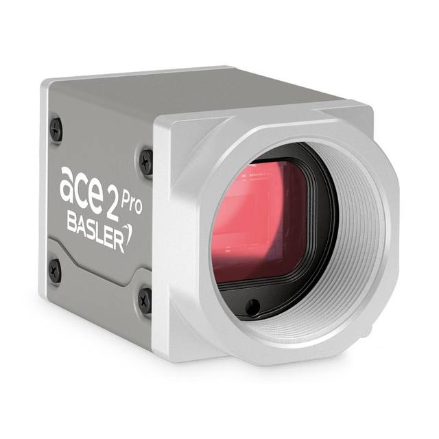
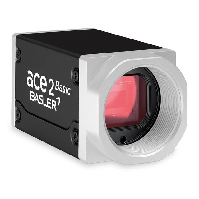
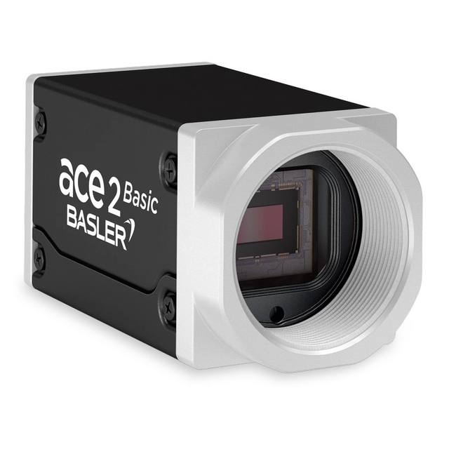
Matched automatically by: camera mount fits the lens mount · camera sensor is covered by the lens image circle — this lens: C-mount · Ø11 mm / 2/3" image circle.
By category
All 758Area scan cameras 622High-speed cameras 108High-resolution cameras 28
By brand
All 758Omron / Sentech 297Basler 242iRAYPLE 200Datalogic / Datasensing 19
Get a first image quickly with the pylon Viewer, then move into the pylon SDK for your application. These cameras are GenICam/GenTL-compliant, so any compliant vision software can drive them as well.
Download and install the pylon Camera Software Suite for your OS from Basler. This provides the pylon Viewer, the GenTL transport-layer producers and the pylon SDK (C/C++/.NET/Python). On Windows the installer adds the needed drivers; on Linux follow the included setup notes for USB and network permissions.
2. Connect the camera and check the link
Cable the camera to its matching interface: GigE Vision to a GigE port (use a quality cable and, ideally, a dedicated NIC with jumbo frames enabled), USB3 Vision to a USB 3.x port with the supplied cable, or CoaXPress to the frame grabber. Provide power where required (PoE, USB bus power, or PoCXP). Open the pylon Viewer and confirm the camera appears in the device list; for GigE, make sure the camera and NIC are on the same subnet.
3. Grab a first image and set exposure, gain and pixel format
Select the camera in the pylon Viewer and start a continuous grab. Adjust exposure time and gain until the image is well exposed (avoid clipped highlights), set the pixel format (e.g. Mono8 or a Bayer/RGB format), and focus the lens. Use a test pattern if the lens or scene is not ready yet.
4. Configure triggering and acquisition
Decide between free-run and triggered acquisition. For synchronized capture, set the trigger source (software or a hardware line on the I/O connector), trigger mode and any debounce or exposure mode, then verify timing. Note the parameter names you change in the Viewer feature tree, as you will reuse them in code.
5. Move to the SDK or a GenICam-compliant library
Recreate your settings in code with the pylon SDK (C, C++, .NET or Python) to open the device, apply the same features and pull frames into your pipeline; pylon vTools and pylon AI can add processing blocks. Because the cameras are GenICam/GenTL standard, third-party vision libraries work too. Once the image stream is stable, you can route frames to a deep-learning inspection such as Rosepetal for automated defect detection.
Frequently asked questions
Telecentric lenses use an aperture stop placed at the front focal point of the optical group. This geometry is what forces the chief ray to run parallel to the axis — but it only works when the object sits at precisely the designed conjugate distance. Moving the object closer or farther shifts the lens out of its telecentric condition, reintroduces perspective error, and changes effective magnification. The 110 mm working distance is therefore a fixed optical constraint, not an adjustable focus setting.
A 2/3" sensor measures approximately 8.8 mm × 6.6 mm. Dividing by 0.3x gives an object field of about 29.3 mm × 22 mm. If you use a camera with fewer megapixels on the same sensor format the field stays the same but per-pixel resolution coarsens; if you use a higher-resolution camera the field stays the same and per-pixel resolution improves — up to the 12.5 µm optical limit at F5.6.
No. The image circle is 11 mm in diameter, which matches the 2/3" format. Any sensor with a diagonal exceeding 11 mm will extend beyond the illuminated field, producing strong vignetting and distortion that invalidates measurements near the frame edges. Choose a 2/3" or smaller sensor camera for this lens.
At F5.6 the lens delivers 12.5 µm object-side resolution, which maximises edge-detection precision for gauging. Closing the iris to F16 or F32 increases the depth of field substantially but reduces the optical resolving power, so the transition from light to dark across an edge becomes slightly softer. For critical width measurements on flat parts, open the iris as wide as the depth-of-field budget allows. For tall components where every feature must stay in focus, stop down and accept the slightly softer edge gradient.
Backlight illumination — a diffuse LED panel placed behind the object at 110 mm — provides the cleanest silhouette for edge-based dimensional gauging and is the most common pairing. For top-side surface or defect inspection a coaxial diffuse illuminator (beam-splitter type) placed on the lens axis preserves the telecentric geometry. Avoid ring lights at steep angles or structured lights whose oblique rays enter the entrance pupil off-axis, as these partially defeat the parallel-ray condition the telecentric design depends on.