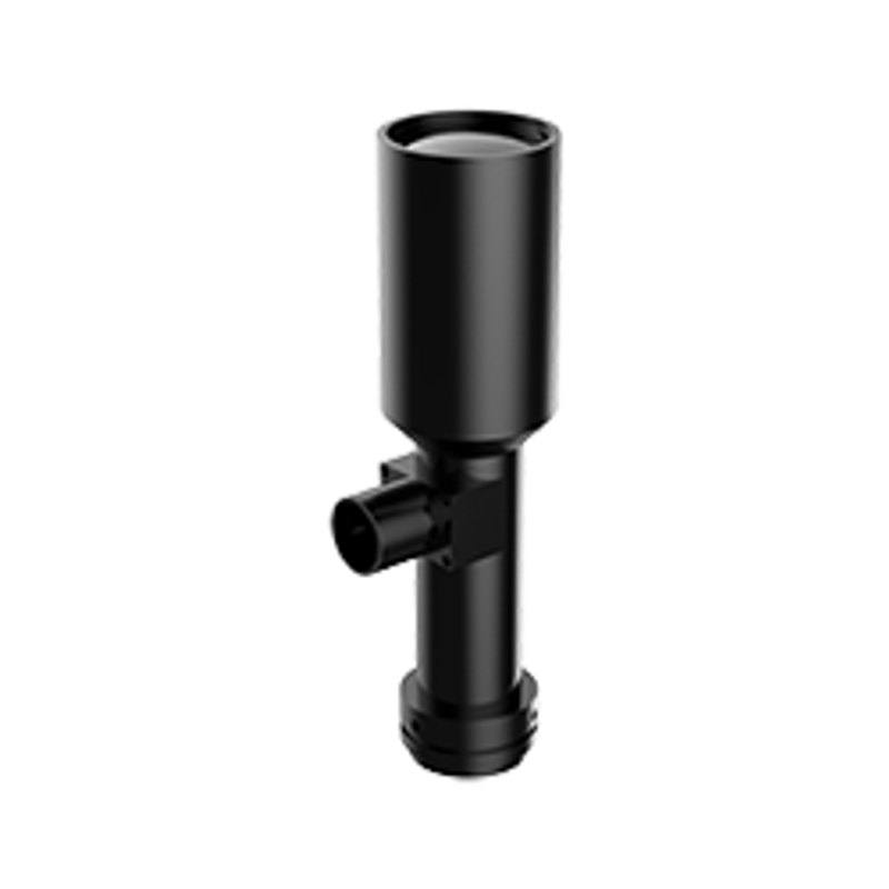
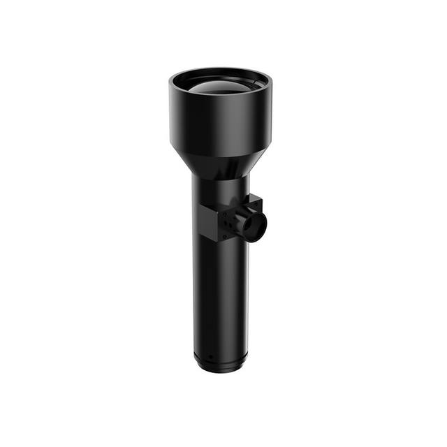
The MTL11-11005XD-C is a bi-telecentric (双远心) machine vision lens designed for dimensional measurement and precision positioning. It provides 0.5× magnification, a φ11 mm image-side field of view, and a nominal working distance of 110 mm (±5%). Distortion is held below 0.095% and telecentricity error below 0.1°, making it suitable for gauging applications up to 2/3" sensor cameras. The lens integrates coaxial illumination capability and delivers uniform image sharpness at 5 MP and 9 MP sensor resolutions.
The iRAYPLE MTL11-11005XD-C is a bi-telecentric lens engineered specifically for high-precision dimensional gauging and measurement in machine vision. Bi-telecentricity means the chief ray is parallel to the optical axis on both the object side and the image side simultaneously. In practice, this eliminates perspective error entirely: objects at slightly different depths within the ±5% working-distance tolerance of 110 mm (approximately 104.5–115.5 mm) produce no change in apparent magnification. For a part that varies a few millimetres in height off a conveyor, the measured pixel footprint stays constant — a property no conventional fixed-focal-length lens can match. The fixed 0.5× magnification maps the object plane directly: a feature 1 mm wide on the part images to 0.5 mm on the sensor, so calibration is stable and repeatable without re-teaching.
At F9.6, depth of field is broad enough to handle modest part height variation while the ø11 mm image circle covers sensors up to 2/3" (the standard 2/3" optical-format diagonal is approximately 11 mm). C-Mount registration keeps the lens compatible with the widest range of area-scan cameras in that sensor class. With distortion held below 0.095% and telecentricity error below 0.1°, the lens meets the geometric accuracy requirements that gauging standards demand: sub-pixel measurement budgets benefit directly from distortion this low. The lens is also validated at 9 MP resolution, confirming that resolving power keeps up with higher-density sensors without sacrificing edge-to-edge sharpness.
The integrated coaxial illumination port is a standout feature for metrology workflows. Coaxial light travels along the optical axis and returns on the same path, producing near-shadowless, specular reflection off flat or polished surfaces. This makes edge detection on metallic, ceramic, or mirror-finished parts dramatically more consistent than off-axis or dome lighting, directly reducing measurement noise. The 110 mm working distance provides enough clearance for part handling fixtures and coaxial light guides to coexist without mechanical interference. Operating across −10 °C to +50 °C, the lens is qualified for controlled factory environments including temperature-cycled semiconductor fabs and automotive assembly cells.
Best for
Dimensional gauging of precision components — measuring diameters, hole positions, edge-to-edge distances, or gap widths where sub-pixel accuracy and magnification stability across height variation are required.
Semiconductor and electronics inspection — component placement verification, lead pitch measurement, and pad inspection on substrates up to 2/3" sensor coverage, where flat-field uniformity and distortion control are critical.
Automotive and metal part conformance — checking machined features, stamped profiles, or formed edges on lines where part height is not perfectly controlled and perspective-induced measurement error must be eliminated.
Coaxial-illumination metrology setups — applications using bright-field coaxial lights to achieve uniform, shadow-free illumination of reflective or polished surfaces, leveraging the lens's built-in coaxial port.
High-repeatability positioning and registration — fiducial alignment, notch detection, or precision assembly guidance where the same calibration must hold across thousands of cycles without recalibration.
Selection notes
Confirm your sensor is 2/3" or smaller. The ø11 mm image circle fits 2/3" sensors at full coverage. Pairing with a 1" or larger sensor will produce vignetting at the corners and invalidate measurements made there.
Fix your working distance before specifying this lens. Bi-telecentric lenses are not focus-adjustable in the conventional sense — the 110 mm working distance (±5%, so approximately 104.5–115.5 mm) is the operating range. Fixtures, conveyors, and part-handling mechanisms must place parts within that window consistently.
Match camera resolution to the resolving power. The lens is validated at 5 MP and 9 MP on 2/3" sensors. Using a camera whose pixel pitch is finer than the lens can resolve will not improve measurement precision and may expose diffraction-limited softness at F9.6.
F9.6 is fixed — there is no iris. Light budget planning must account for a relatively modest aperture. Coaxial or structured illumination with sufficient intensity is essential; strobe-mode driving of LED sources is recommended to achieve the high instantaneous intensity needed while keeping heat and exposure low.
The 0.5× magnification sets the object-space field of view directly from sensor size: divide each sensor dimension by 0.5 (multiply by 2) to obtain the object-space coverage. Verify this covers your largest part feature before ordering.
Specifications: General
Brand
iRAYPLE
Specifications: Optical
Lens mount
C-Mount
Magnification
0.5×
Image circle / max sensor
φ11 mm (≤2/3")
Working distance
110 mm ±5%
Aperture (f-number)
F9.6
Telecentric
Yes (bi-telecentric)
Specifications: Environment
Operating temperature
-10°C to +50°C
Specifications: Mechanical
Dimensions
126.9 mm × φ35 mm
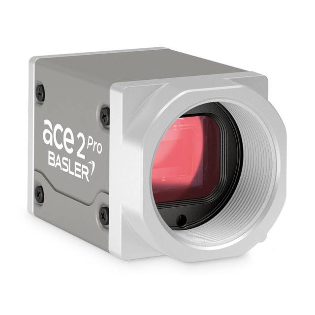
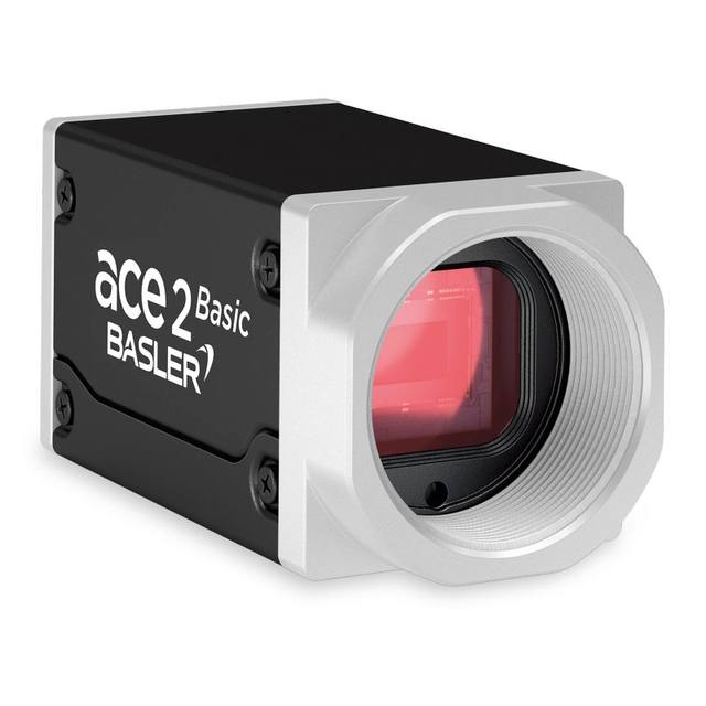
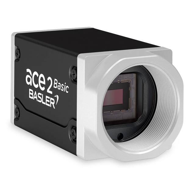
Applications this camera is commonly selected for. Open one to see the full recommended hardware and approach.
Matched automatically by: camera mount fits the lens mount · camera sensor is covered by the lens image circle — this lens: C-Mount · φ11 mm (≤2/3") image circle.
By category
All 758Area scan cameras 622High-speed cameras 108High-resolution cameras 28
By brand
All 758Omron / Sentech 297Basler 242iRAYPLE 200Datalogic / Datasensing 19
Follow these steps to bring up your iRAYPLE camera, capture a first image, and move from the viewer to your own application. The flow is the same across the A, AE, AX and L series; only the physical interface differs.
Download and install the iRAYPLE machine-vision SDK together with its viewer client for your operating system. The installer provides the camera drivers, the GenTL producer, and the viewer you will use for first light. For GigE Vision models, also install or enable the bundled filter/performance driver on the network adapter to maximize throughput.
2. Connect the camera to the correct interface
Wire the camera to its matching host interface: a dedicated Gigabit (or 10 GigE) NIC for GigE Vision models, a USB3 Vision port with a quality cable for USB3 models, or a frame grabber for CoaXPress models. Power the camera (PoE, USB bus power, or PoCXP / external supply as applicable). For GigE Vision, put the NIC and camera on the same subnet and, where supported, enable jumbo frames.
3. Detect and open the camera in the viewer
Launch the iRAYPLE viewer, run device enumeration, and select your camera from the discovered list. Open it to load the device feature tree (GenICam node map). If a GigE camera is found but cannot be opened, correct the IP configuration so the camera and NIC are in the same address range.
4. Set exposure, gain and trigger, then grab a first image
Start with continuous (free-run) acquisition under stable lighting. Adjust exposure time and gain for a well-exposed, low-noise image, set the pixel format (e.g. Mono8 or a Bayer/RGB format), and tune white balance on color models. Once the live image looks correct, switch trigger mode to hardware or software trigger to synchronize capture with your process, and verify a single triggered frame.
5. Move from the viewer to the SDK or a GenICam library
With imaging confirmed, reproduce the same settings in code using the SDK's C/C++ or Python API: enumerate, open, configure the relevant GenICam features, register a frame callback or grab loop, and convert frames to your pipeline's buffer format. Since the cameras are GenICam/GenTL-compliant, you can alternatively drive them from a third-party GenICam vision library. From here a stable image stream can feed a deep-learning inspection step such as Rosepetal for automated quality control.
Frequently asked questions
A bi-telecentric lens keeps the chief ray parallel to the optical axis on both sides of the lens. On the object side, this means magnification does not change with object distance — a part a few millimetres closer or farther than nominal images at exactly the same size. On the image side, it means the angle of incidence at the sensor is constant across the field, which keeps radiometric response uniform. Together, these properties eliminate the perspective-induced sizing errors that affect conventional lenses, making the MTL11-11005XD-C suitable for absolute dimensional measurement rather than only comparative inspection.
Because magnification is fixed at 0.5×, object-space field of view is simply the sensor's active area divided by 0.5 — equivalently, each sensor dimension multiplied by 2. For example, a 2/3" sensor with an 8.45 × 7.07 mm active area yields an object-space FOV of approximately 16.9 × 14.1 mm. Check your camera datasheet for the exact active sensor dimensions to compute your specific FOV.
Technically yes — the C-Mount fits color cameras with a 2/3" sensor. However, bi-telecentric lenses for precision gauging are typically paired with monochrome cameras. Monochrome sensors have higher quantum efficiency and eliminate color-filter-array interpolation artifacts, both of which improve sub-pixel edge localization. If your application is purely dimensional measurement, a monochrome camera will give more repeatable results.
The coaxial port accepts coaxial light guides that introduce light along the optical axis, producing on-axis illumination that returns specular reflection from flat, polished, or mirror-finished surfaces directly into the lens — maximizing contrast on edges and surface features. For diffuse or matte surfaces, coaxial lighting still provides very even, shadow-free illumination. Strobe-mode driving of LED sources is recommended to achieve the high instantaneous intensity F9.6 demands while keeping heat and exposure low.
The lens itself imposes no speed limitation — it has no moving parts or adjustable iris. Production throughput depends on the camera frame rate and how fast the illumination can be strobed. The −10 °C to +50 °C operating range covers typical factory floors. The main inline constraint is mechanical: parts must reliably arrive within the ±5% working-distance window of 110 mm. If your transport system delivers consistent part height, this lens is fully suitable for high-rate inline gauging.