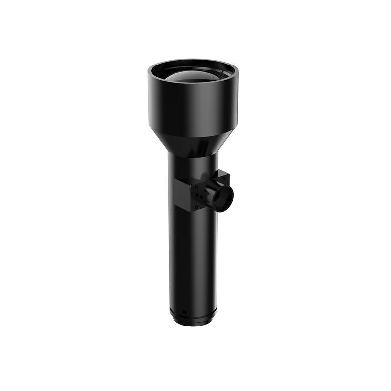
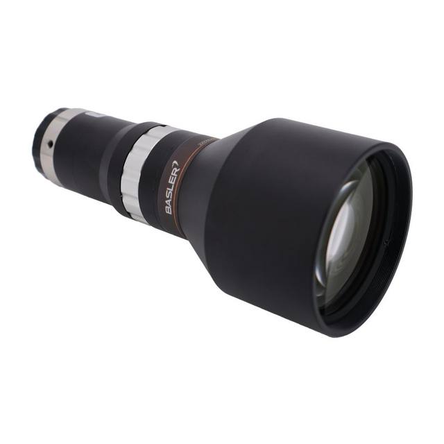
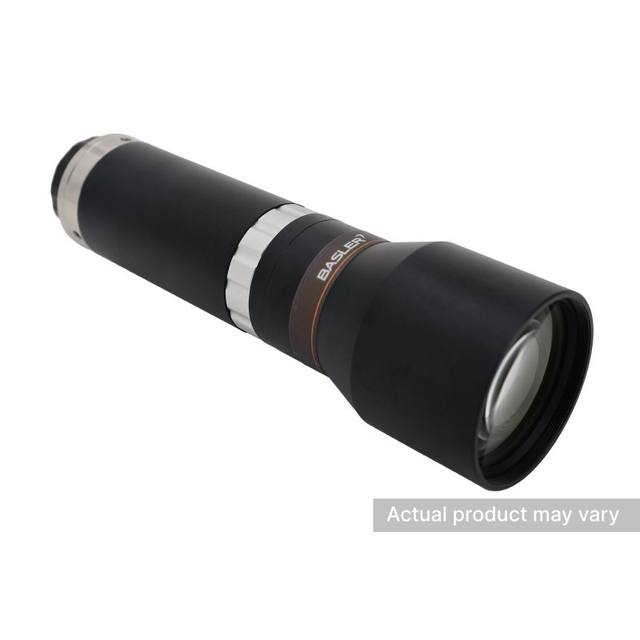
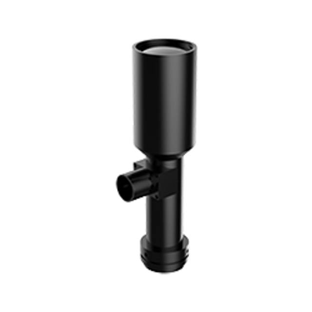
The MTL17-11010XD-C is an object-side telecentric (物方远心) machine vision lens offering 1× magnification and covering a 1.1" image circle (φ17.6 mm). Working distance is 110 mm (±3%), aperture F10, and depth of field 1.1 mm. Distortion is below 0.08% and telecentricity error below 0.08°, targeting high-accuracy gauging tasks requiring 12 MP or 20 MP cameras. Optional coaxial illumination is available, and the lens delivers uniform image clarity across the full field.
The iRAYPLE MTL17-11010XD-C is an object-side telecentric lens designed specifically for high-precision dimensional gauging. At 1x magnification, the image projected onto the sensor is the same physical size as the object being inspected — every millimeter on the part corresponds to exactly one millimeter on the sensor plane. Unlike conventional lenses, which cast diverging perspective rays and cause apparent size changes as an object moves toward or away from the lens, this telecentric design ensures that all chief rays travel parallel to the optical axis on the object side. The practical consequence is that axial displacement of the part (within the ±3% tolerance of the 110 mm working distance) does not distort or rescale the measured feature. Distortion is specified at below 0.08% and telecentricity error at below 0.08°, both extremely tight tolerances that translate directly into reliable sub-pixel measurement accuracy for automated gauging systems.
The lens covers a 1.1" image circle (ø17.6 mm) via its C-mount interface, making it compatible with sensors up to the 1.1" format — including 12 MP and 20 MP high-resolution CMOS sensors commonly used in precision inspection. At 1x magnification, the field of view equals the sensor size, so the full resolution of the sensor is available across the entire inspection field. The fixed working distance of 110 mm and the fixed aperture of F10 together yield a depth of field of 1.1 mm — narrow enough to reject out-of-focus background clutter on a production line, yet sufficient to accommodate minor part height variation in typical gauging fixtures. The F10 aperture is deliberately conservative: a tighter aperture than a fast consumer lens, it reduces diffraction edge effects and improves geometric sharpness for measurement rather than photographic imaging.
Optional coaxial illumination compatibility is a key practical advantage of this lens. Coaxial (on-axis) illumination floods the object surface with light traveling along the same axis as the lens, eliminating shadows in flat, specular, or structured surfaces and producing uniform, high-contrast silhouettes of edges and holes — the very features used in dimensional gauging algorithms. The ø50 × 151.5 mm cylindrical body and −10 °C to +50 °C operating range reflect an industrial-duty design intended for integration into automated optical inspection (AOI) stations, semiconductor metrology setups, and inline measurement cells in electronics and automotive manufacturing.
Best for
High-accuracy dimensional measurement tasks where absolute magnification consistency is required — inspecting connector pin pitch, PCB feature dimensions, machined part tolerances, or stamped metal geometry without recalibrating for part height variation.
20 MP or 12 MP sensor-based vision systems where the full 1.1" image circle must be covered without vignetting, maximizing the measurement field while preserving uniform image quality corner to corner.
Inline gauging fixtures where the object-to-lens distance is mechanically controlled to approximately 110 mm and the part surface is relatively flat, allowing the 1.1 mm depth of field to encompass the full inspection zone.
Semiconductor and electronics inspection applications requiring sub-pixel edge localization, where conventional lens distortion (even at <0.1%) would introduce systematic measurement bias that telecentric optics eliminates.
Pharmaceutical blister pack, medical device, and precision automotive component inspection lines where regulatory or process requirements demand dimensional traceability and repeatable optical magnification.
Selection notes
Verify your sensor format before ordering. The MTL17-11010XD-C covers up to 1.1" (ø17.6 mm). Using it with a larger sensor format will result in vignetting at the corners; using it with a smaller sensor simply reduces the usable field of view proportionally at 1x magnification.
The working distance is fixed at 110 mm (±3%). This is not an adjustable-focus lens — the entire measurement setup (conveyor height, part fixture, gantry clearance) must be engineered to place the object surface at 110 mm from the lens front. Confirm mechanical clearance for the 151.5 mm body length plus camera depth.
At F10, the lens requires adequate illumination for the desired exposure time and camera gain. Coaxial illumination is strongly recommended over diffuse or ring lighting to maximize edge contrast on flat or reflective parts; strobed coaxial LED illumination synchronized to the camera trigger is the standard pairing.
The 1.1 mm depth of field is a hard constraint. Parts with significant height variation across the inspection region (warped PCBs, tall connectors, three-dimensional features) may show blur at height extremes. For taller features, consider a different telecentric lens in the MTL17 series with a larger specified depth of field or a step-and-scan strategy.
C-mount compatibility means any C-mount industrial camera body can be directly attached. Confirm the camera's flange focal distance is standard C-mount (17.526 mm) and that no extension rings are in the optical path, as telecentric lenses are sensitive to back-focal-distance changes that shift the working distance and degrade telecentricity performance.
Specifications: General
Brand
iRAYPLE
Specifications: Optical
Lens mount
C-Mount
Magnification
1×
Image circle / max sensor
1.1" / φ17.6 mm
Working distance
110 mm ±3%
Aperture (f-number)
F10
Telecentric
Yes (object-side telecentric)
Specifications: Environment
Operating temperature
-10°C to +50°C
Specifications: Mechanical
Dimensions
φ50 × 151.5 mm
Applications this camera is commonly selected for. Open one to see the full recommended hardware and approach.
Matched automatically by: camera mount fits the lens mount · camera sensor is covered by the lens image circle — this lens: C-Mount · 1.1" / φ17.6 mm image circle.
Follow these steps to bring up your iRAYPLE camera, capture a first image, and move from the viewer to your own application. The flow is the same across the A, AE, AX and L series; only the physical interface differs.
Download and install the iRAYPLE machine-vision SDK together with its viewer client for your operating system. The installer provides the camera drivers, the GenTL producer, and the viewer you will use for first light. For GigE Vision models, also install or enable the bundled filter/performance driver on the network adapter to maximize throughput.
2. Connect the camera to the correct interface
Wire the camera to its matching host interface: a dedicated Gigabit (or 10 GigE) NIC for GigE Vision models, a USB3 Vision port with a quality cable for USB3 models, or a frame grabber for CoaXPress models. Power the camera (PoE, USB bus power, or PoCXP / external supply as applicable). For GigE Vision, put the NIC and camera on the same subnet and, where supported, enable jumbo frames.
3. Detect and open the camera in the viewer
Launch the iRAYPLE viewer, run device enumeration, and select your camera from the discovered list. Open it to load the device feature tree (GenICam node map). If a GigE camera is found but cannot be opened, correct the IP configuration so the camera and NIC are in the same address range.
4. Set exposure, gain and trigger, then grab a first image
Start with continuous (free-run) acquisition under stable lighting. Adjust exposure time and gain for a well-exposed, low-noise image, set the pixel format (e.g. Mono8 or a Bayer/RGB format), and tune white balance on color models. Once the live image looks correct, switch trigger mode to hardware or software trigger to synchronize capture with your process, and verify a single triggered frame.
5. Move from the viewer to the SDK or a GenICam library
With imaging confirmed, reproduce the same settings in code using the SDK's C/C++ or Python API: enumerate, open, configure the relevant GenICam features, register a frame callback or grab loop, and convert frames to your pipeline's buffer format. Since the cameras are GenICam/GenTL-compliant, you can alternatively drive them from a third-party GenICam vision library. From here a stable image stream can feed a deep-learning inspection step such as Rosepetal for automated quality control.
Frequently asked questions
At 1x magnification, one millimeter on the object maps to exactly one millimeter on the sensor. Because the telecentric design keeps this ratio constant regardless of small axial shifts in the part's position, you can convert pixels to physical units with a single calibration factor that remains stable over time. By contrast, a conventional (entocentric) lens changes its effective magnification as the object moves closer or farther, introducing a perspective error that grows with distance from the nominal focal plane.
At 1x magnification the field of view equals the sensor's physical dimensions. The exact coverage depends on the specific sensor's pixel size and array format; for a 1.1" format 20 MP sensor, the physical sensor dimensions determine the inspection window at 110 mm working distance. If you need a larger field, you would need a different telecentric lens with a lower magnification, which trades spatial resolution for coverage.
It can accept external ring illumination, but coaxial illumination typically delivers superior results for the gauging tasks this lens targets. Coaxial light travels along the optical axis, producing flat, uniform illumination across the field and creating sharp, high-contrast shadow-free silhouettes of holes, edges, and slots — the features that gauging algorithms measure. Ring lights at close working distances can create uneven brightness gradients and specular reflections that compromise edge-detection accuracy.
Yes, and coaxial illumination is especially beneficial here. Specular surfaces reflect light directionally; coaxial illumination returns that specular reflection directly back into the lens, making bright flat surfaces appear uniformly bright and edges appear dark — a high-contrast inversion that edge-detection algorithms handle very well. For oxidized, anodized, or textured metal surfaces, a combination of coaxial and low-angle ring illumination may be evaluated.
Distortion causes straight lines at the periphery of the field to appear curved, shifting pixel positions away from their geometrically correct locations. At 0.08% distortion, the maximum positional error scales with the field width: for a given sensor's physical width W, the corner error is approximately 0.08% × W ÷ 2. For most sub-pixel gauging applications this is negligible, but if your tolerance budget is especially tight, a software distortion-correction map can reduce residual error further.