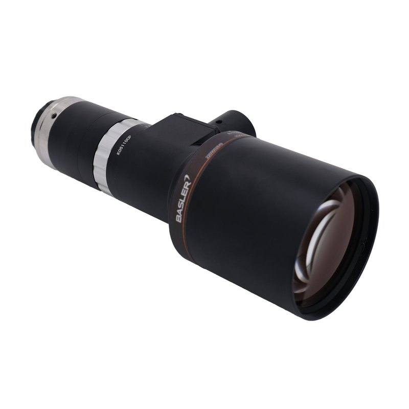
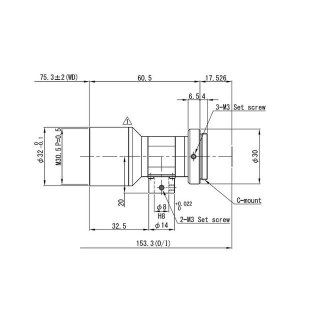
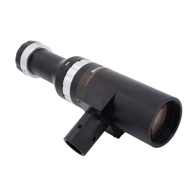
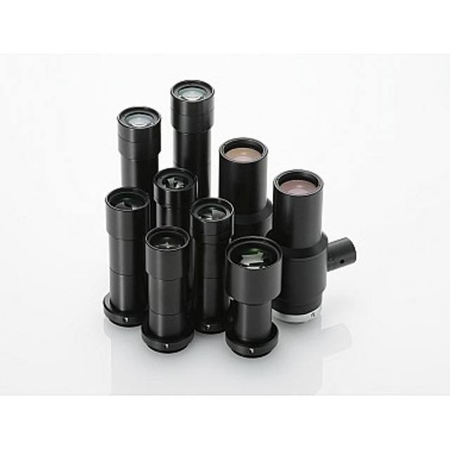
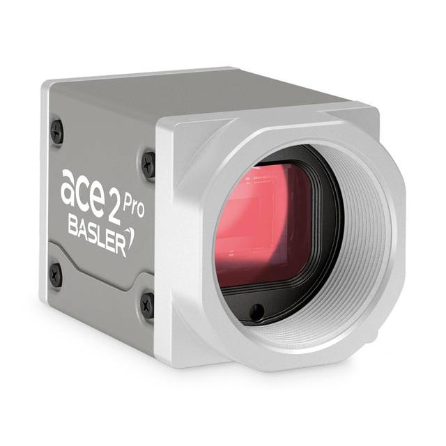
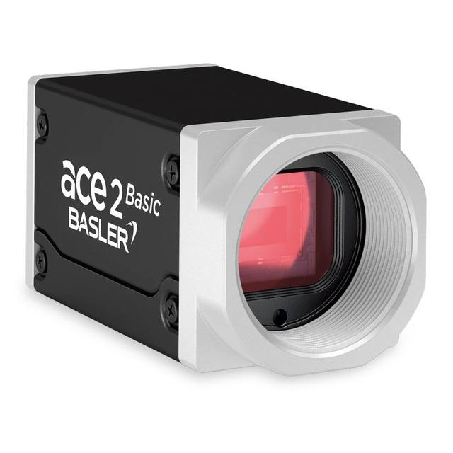
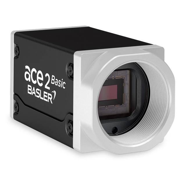
The Basler C11T-05-110-VI-C is a single-sided telecentric lens designed for precise dimensional measurement, offering a fixed 0.5x magnification and 110 mm working distance with object-side telecentricity of 0.02° max. It covers a 1.1" sensor format (18.2 mm image circle) with an aperture range of F7–F32 and achieves theoretical object-side resolution of 10.1–45.9 µm depending on f/#. The lens features a manual variable iris, metal housing, C-mount interface, and an integrated coaxial illumination input port for axial lighting setups. Wavelength coverage spans the visible spectrum (400–700 nm).
The Basler C11T-05-110-VI-C is a single-sided telecentric C-mount lens built around a fixed 0.5x magnification and a tightly controlled object-side telecentricity of 0.02° maximum. Telecentricity at this level means that the chief ray on the object side runs parallel to the optical axis regardless of aperture setting, so the apparent size of a part does not change as it moves slightly toward or away from the lens along the Z axis. In a dimensional gauging cell—where a conveyor or fixture may have several millimetres of Z-axis variation part to part—this property directly eliminates magnification-induced measurement error that would plague a conventional entocentric lens. The fixed 110 mm working distance gives integrators a well-defined standoff that comfortably clears guards, conveyors, and the coaxial illumination head without requiring any focus adjustment between parts.
The 18.2 mm image circle covers the full 1.1" sensor diagonal, making this lens directly compatible with the increasingly common 1.1" format large-format area-scan sensors. Using the full sensor area at 0.5x magnification produces an object field of roughly 36.4 mm across the diagonal, allowing a single camera to inspect a medium-format part without mechanical stitching. The variable iris spans F7 to F32, and the theoretical object-side resolution ranges from 10.1 µm at F7 to 45.9 µm at F32. Opening toward F7 maximises spatial resolution and is appropriate when fine feature detail must be resolved; stopping down toward F32 extends depth of field at the cost of resolution, which can be useful for parts with moderate height relief or surface texture. The manual iris ring lets an installer set depth-of-field and exposure balance once at setup and leave it locked, consistent with an automated line environment.
The integrated coaxial illumination input port is a standout integration feature. Coaxial (on-axis) lighting eliminates side-cast shadows and returns a specular reflection from flat, polished, or mirrored surfaces directly back through the lens toward the sensor, producing uniform bright-field images ideal for reading laser-etched codes, inspecting flat PCB pads, or gauging metallic stamped parts. Having the illumination path built into the lens barrel eliminates a separate beam-splitter cube and reduces the total optical stack height compared to external coaxial setups. The metal housing ensures dimensional stability under factory thermal cycling and vibration, and the C-mount interface is universally supported across a wide range of GigE and USB3 Vision cameras with 1.1" or smaller sensors.
Best for
Precision dimensional gauging of flat or low-relief parts (stamped metal, machined components, electronic connectors) where sub-pixel measurement accuracy requires elimination of perspective error across Z-axis part height variation
Direct Part Mark (DPM) and laser-etched code reading on polished or specular metal surfaces, leveraging the integrated coaxial illumination port to produce uniform bright-field contrast on low-contrast marks
PCB solder-pad inspection, BGA land measurement, and fine-pitch component presence/absence checks on boards up to roughly 36 mm diagonal at a comfortable 110 mm standoff
Pharmaceutical blister-pack and tablet dimensional verification where consistent magnification across slightly non-planar foil surfaces is required without mechanical focus actuation between cavities
Surface defect detection on mirror-finish or electroplated parts in automotive and semiconductor packaging where coaxial lighting is essential for revealing micro-scratches and pinholes with flat-field uniformity
Selection notes
Sensor format compatibility: the 18.2 mm image circle fully illuminates 1.1" sensors but also covers all smaller formats (1", 2/3", 1/1.8", etc.). Confirm your camera's sensor diagonal is 18.2 mm or less to avoid vignetting; if migrating from a smaller-format lens to a 1.1" sensor, this lens removes the format bottleneck entirely.
Fixed magnification means the field of view is determined solely by the sensor size. At 0.5x on a full 1.1" sensor the object field diagonal is approximately 36.4 mm; for a 4:3 chip with an 18.2 mm diagonal the object field is approximately 29.1 mm × 21.8 mm. Verify this object field covers your largest expected part; the magnification cannot be adjusted in the field, so FOV changes require a different lens model.
The fixed 110 mm working distance is non-negotiable — unlike a varifocal lens there is no focus ring. Integration design must position the lens mount precisely at 110 mm from the part plane. Account for the coaxial illuminator body depth when calculating total head height and fixture clearances.
Aperture selection trades resolution against depth of field: the 10.1 µm resolution at F7 is appropriate for fine-feature inspection at tight tolerances, while F16–F32 is more forgiving for height-varying parts. Set aperture during system qualification and mechanically lock or mark the iris ring to prevent drift from vibration.
Coaxial illumination pairing: the integrated port accepts a coaxial light source designed for use with the lens's built-in illumination path. Confirm the illuminator wavelength falls within the visible range (400–700 nm). If using a strobe controller, verify its output current is within the illuminator's strobe rating to avoid thermal damage during high-duty-cycle operation.
Specifications: General
Brand
Basler
Specifications: Optical
Lens mount
C-mount
Telecentric
Yes
Magnification
0.5x
Working distance
110 mm
Aperture (f-number)
F7–F32
Image circle / max sensor
18.2 mm (1.1" format)
Specifications: Mechanical
Housing material
Metal
Applications this camera is commonly selected for. Open one to see the full recommended hardware and approach.
Matched automatically by: camera mount fits the lens mount · camera sensor is covered by the lens image circle — this lens: C-mount · 18.2 mm (1.1" format) image circle.
Get a first image quickly with the pylon Viewer, then move into the pylon SDK for your application. These cameras are GenICam/GenTL-compliant, so any compliant vision software can drive them as well.
Download and install the pylon Camera Software Suite for your OS from Basler. This provides the pylon Viewer, the GenTL transport-layer producers and the pylon SDK (C/C++/.NET/Python). On Windows the installer adds the needed drivers; on Linux follow the included setup notes for USB and network permissions.
2. Connect the camera and check the link
Cable the camera to its matching interface: GigE Vision to a GigE port (use a quality cable and, ideally, a dedicated NIC with jumbo frames enabled), USB3 Vision to a USB 3.x port with the supplied cable, or CoaXPress to the frame grabber. Provide power where required (PoE, USB bus power, or PoCXP). Open the pylon Viewer and confirm the camera appears in the device list; for GigE, make sure the camera and NIC are on the same subnet.
3. Grab a first image and set exposure, gain and pixel format
Select the camera in the pylon Viewer and start a continuous grab. Adjust exposure time and gain until the image is well exposed (avoid clipped highlights), set the pixel format (e.g. Mono8 or a Bayer/RGB format), and focus the lens. Use a test pattern if the lens or scene is not ready yet.
4. Configure triggering and acquisition
Decide between free-run and triggered acquisition. For synchronized capture, set the trigger source (software or a hardware line on the I/O connector), trigger mode and any debounce or exposure mode, then verify timing. Note the parameter names you change in the Viewer feature tree, as you will reuse them in code.
5. Move to the SDK or a GenICam-compliant library
Recreate your settings in code with the pylon SDK (C, C++, .NET or Python) to open the device, apply the same features and pull frames into your pipeline; pylon vTools and pylon AI can add processing blocks. Because the cameras are GenICam/GenTL standard, third-party vision libraries work too. Once the image stream is stable, you can route frames to a deep-learning inspection such as Rosepetal for automated defect detection.
Frequently asked questions
The image circle is 18.2 mm, which corresponds exactly to the 1.1" sensor format diagonal. Any sensor with a diagonal of 18.2 mm or less — including 1", 2/3", and smaller formats — will be fully illuminated. Sensors larger than 1.1" will exhibit vignetting and should not be used with this lens.
No. This is a fixed-magnification telecentric lens with a defined working distance of 110 mm. There is no focus ring or zoom mechanism. The 0.5x magnification and 110 mm standoff are fixed optical properties. To change the field of view you must select a different magnification variant or change the camera sensor size.
Theoretical object-side resolution ranges from 10.1 µm at the widest aperture (F7) to 45.9 µm at the smallest aperture (F32). Opening to F7 gives the finest resolvable detail for high-precision measurement or fine-feature inspection; stopping to F32 sacrifices resolution but extends depth of field, useful for parts with surface relief or height variation.
The lens covers the visible spectrum from 400 to 700 nm. Illumination sources used with the coaxial input port should emit within this range. UV or near-infrared sources outside this band are not specified and may produce degraded contrast or resolution.
The lens uses a standard C-mount interface and is compatible with any C-mount camera whose sensor diagonal is 18.2 mm or less. This includes cameras with 1.1" or smaller sensors across GigE Vision, USB3 Vision, and CoaXPress form factors.