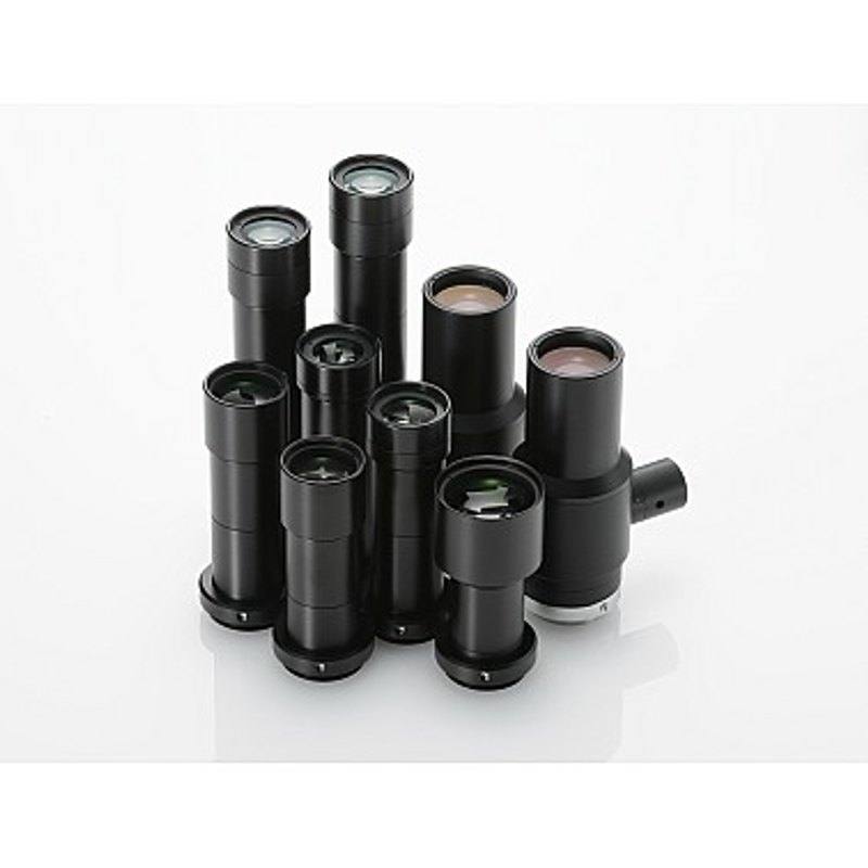
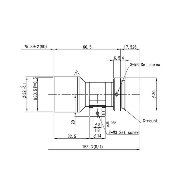
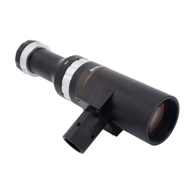
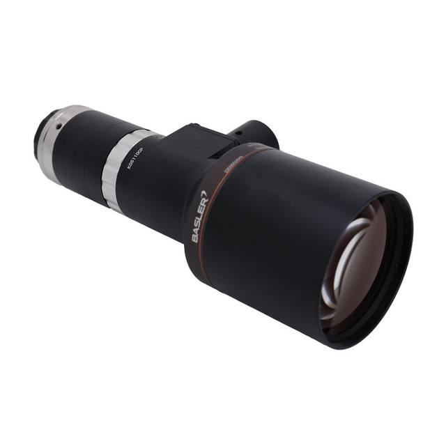
The Omron 3Z4S-LE VS-TCH1-110-O is a straight-body, high-resolution telecentric lens designed for megapixel C-mount machine vision cameras, offering 1.0x (±5%) optical magnification at a working distance of 110.3 mm. It delivers 6.99 µm resolution (at 550 nm), a depth of field of 0.84 mm, and extremely low TV distortion of 0.02%, making it well-suited for precision dimensional measurement and alignment. The lens supports up to a 2/3-inch sensor with a field of view of 6.6 × 8.8 mm and 99% relative illuminance at full field. At Ø30 mm × 129 mm and 92 g, it is compact and practical for integration in automated inspection systems.
The Omron VS-TCH1-110-O is an object-space telecentric lens operating at exactly 1.0x magnification (±5%), which means every point in the object plane is imaged at unit scale regardless of minor axial shifts within the depth of field. This telecentric geometry eliminates the perspective error that plagues conventional lenses when measuring parts at slightly different heights — a critical property when inspecting machined components, semiconductor packages, or pharmaceutical tablets whose surfaces are never perfectly coplanar. At a fixed 110.3 mm working distance, the lens imposes an object-space field of view of 6.6 × 8.8 mm when paired with cameras using up to a 2/3-inch sensor. Installers should note that the working distance is fixed by design: unlike a standard macro lens, there is no focusing ring that trades off magnification against distance. The part must arrive repeatably at 110.3 mm from the front of the lens barrel.
Resolution is specified at 6.99 µm (at 550 nm wavelength), which sets the finest feature the optical system can resolve before the sensor pixel pitch becomes the limiting factor. On a megapixel camera with a 2/3-inch sensor, the lens resolves features on the object down to roughly 7 µm — suitable for detecting edge chips on silicon dies, ink-jet dot placement, fine lead-pitch solder, or printed character strokes. The F10.49 fixed aperture delivers a depth of field of 0.84 mm, narrow enough to reject background clutter yet wide enough to tolerate the small height variation present in most precision parts. TV distortion is rated at 0.02%, which at an 8.8 mm field translates to a worst-case positional error of under 2 µm across the full image — essential for dimensional measurement where sub-pixel accuracy is expected. Relative illuminance at full field is 99%, meaning brightness falloff from center to corner is negligible, allowing threshold-based edge detection and binarization to perform consistently across the entire field without flat-field correction.
At Ø30 mm × 129 mm and 92 g, the lens body is compact enough to mount directly on a standard C-mount camera without additional support brackets in most orientations, simplifying mechanical integration. The straight-body form factor is particularly convenient in gantry or inline fixtures where a coaxial or ring illuminator must be placed around the lens barrel. Because telecentric lenses require a front aperture at least as wide as the magnified pupil, installers planning coaxial illumination should verify that their beam-splitter cube fits within the 110.3 mm working distance budget. Diffuse on-axis or dome illumination is generally preferred for reflective metallic surfaces; structured or directional side lighting can be added to highlight surface relief, but the telecentric geometry will still interpret any height variation within the 0.84 mm DoF as being in focus.
Best for
Precision dimensional gauging of small machined parts, stamped metal components, or molded plastic features where height variation of up to 0.84 mm must not introduce magnification error
Semiconductor and electronics inspection — die attach positioning, BGA pad layout verification, fine-pitch lead inspection — where a 6.6 × 8.8 mm field of view covers a single component or small panel region with sub-pixel geometric accuracy
Pharmaceutical tablet and capsule measurement for diameter, coating uniformity, and print legibility, where consistent unit-magnification across the full tablet face is required for regulatory traceability
OCR/OCV on small labels, direct part marks (DPM), or engraved part numbers where 0.02% TV distortion ensures character geometry is not distorted and recognition algorithms see undistorted strokes
Wafer or glass substrate edge-chip detection in semiconductor and display manufacturing, where the flat, high-uniformity illumination field (99% relative illuminance) enables reliable binarization to find micron-scale defects
Selection notes
The working distance is fixed at 110.3 mm — there is no adjustment. Your mechanical fixture must position the part at exactly this distance from the lens front. Verify that your conveyor, pallet, or pick-and-place system can hold that tolerance, and leave clearance in the machine envelope for the 129 mm body length behind the C-mount face.
The image circle covers a maximum 2/3-inch sensor. Mounting this lens on a camera with a larger sensor (e.g., 1-inch or 4/3-inch) will introduce vignetting in the corners. For best uniformity, select a camera whose sensor is 2/3-inch or smaller.
The F10.49 aperture is fixed and cannot be adjusted. This limits light throughput compared to lower F-number lenses. Under typical LED illumination, you will need either a high-luminance ring or dome light, a high-sensitivity camera, or a strobe controller to achieve adequate exposure at production line speeds. Budget for adequate illumination intensity before finalizing integration.
At 1.0x magnification, every micrometer of object feature maps to one micrometer on the sensor. The effective system resolution is therefore determined by whichever is coarser: the lens optical resolution (6.99 µm) or the camera pixel pitch. To avoid the camera pixel pitch becoming the resolution bottleneck, select a camera with a pixel pitch at or below approximately 7 µm, consistent with the lens's specified optical resolution.
TV distortion of 0.02% is extremely low but not zero. For the most demanding metrology applications (sub-micron tolerances), a per-unit distortion calibration step using a calibration grid is recommended, particularly if the camera's pixel array flatness or lens-to-sensor alignment introduces additional systematic error.
Specifications: General
Brand
Omron / Sentech
Specifications: Optical
Lens mount
C-mount
Telecentric
Yes
Magnification
1.0x (±5%)
Working distance
110.3 mm
Aperture (f-number)
F10.49
Image circle / max sensor
2/3 inch (max sensor)
Specifications: Mechanical
Dimensions
Ø30 (max) × 129.0 mm
Weight
92 g
Applications this camera is commonly selected for. Open one to see the full recommended hardware and approach.
Matched automatically by: camera mount fits the lens mount · camera sensor is covered by the lens image circle — this lens: C-mount · 2/3 inch (max sensor) image circle.
By category
All 758Area scan cameras 622High-speed cameras 108High-resolution cameras 28
By brand
All 758Omron / Sentech 297Basler 242iRAYPLE 200Datalogic / Datasensing 19
These steps take an Omron Sentech (STC) camera from the box to a stable first image and on to your own application. They apply across the GigE Vision, USB3 Vision and CoaXPress STC families; the interface only changes how you cable and power the camera.
Download and install the Sentech SDK on the host PC. The package provides StViewer, the viewing and configuration software you use to bring the camera up, and StApi, the programming SDK you integrate later. Because the cameras are GenICam/GenTL-compliant, StApi also registers a GenTL producer, so any GenICam-compliant third-party vision software can discover and drive the camera as an alternative front end.
2. Cable, power and connect the camera
Connect according to the interface. GigE Vision: link to a Gigabit NIC (use PoE or the separate power input) and put the camera and host on the same subnet; for USB3 Vision use a USB 3.x port and a certified cable; for CoaXPress (STC) connect to a CoaXPress frame grabber, which also supplies Power-over-Coax. Then open StViewer and let it enumerate the camera. If a GigE camera does not appear, check the IP configuration and firewall, and on USB3 confirm the host bandwidth and driver.
3. Configure exposure, gain and white balance
Open the device in StViewer and start a live stream. Set exposure and gain for a well-exposed, low-noise image: raise exposure first and only add gain when more light or a faster shutter is not an option, keeping exposure short enough to freeze motion on global-shutter models. On colour cameras, run white balance under your actual production lighting. Adjust the lens aperture and focus on a representative target before tuning anything else.
4. Set the trigger and grab a first image
Start in free-run (continuous) acquisition to confirm a clean, stable image. For inline inspection switch to hardware or software triggering: select the trigger source, set the active edge and any delay, and wire the strobe or illumination to the camera's I/O so lighting fires with each exposure. Acquire and save a frame in StViewer; this saved image is your reference for the SDK stage and for downstream inspection.
5. Move to the StApi SDK (or any GenICam software)
Once the image is stable, reproduce the same settings in code. Use StApi to open the device, apply the GenICam features you validated in StViewer (exposure, gain, trigger, pixel format) and grab frames into your application via the bundled C++, C, C#/.NET or Python interfaces; the included samples are the fastest starting point. Prefer a different stack? The same GenICam/GenTL camera works with third-party vision libraries. With a reliable feed, you can route it into a deep-learning inspection such as Rosepetal for AI-based defect detection.
Frequently asked questions
At the fixed 110.3 mm working distance and 1.0x magnification, the field of view is 6.6 × 8.8 mm when paired with a 2/3-inch sensor (the maximum supported sensor size). Smaller sensors will produce proportionally smaller fields of view at the same magnification.
No. This is a fixed-magnification telecentric lens rated at 1.0x (±5%). There is no focusing or zoom adjustment. The working distance is fixed at 110.3 mm. If your application requires a different field of view or standoff, you would need a different telecentric lens model.
The lens uses a standard C-mount, compatible with the large installed base of C-mount machine vision cameras.
At the 8.8 mm field width, 0.02% distortion corresponds to a maximum geometric positional error of approximately 1.8 µm at the extreme corners of the image. For most industrial gauging applications this is negligible compared to other system error sources. For sub-micron metrology, a distortion calibration step using a precision grid target is advisable.
The specs do not prescribe a specific illuminator, but the F10.49 aperture limits light throughput, so high-brightness diffuse illumination — a dome light, coaxial LED, or ring light positioned within the 110.3 mm working distance — is recommended. Strobe mode can help freeze motion at high line speeds while maintaining adequate exposure with the fixed aperture.