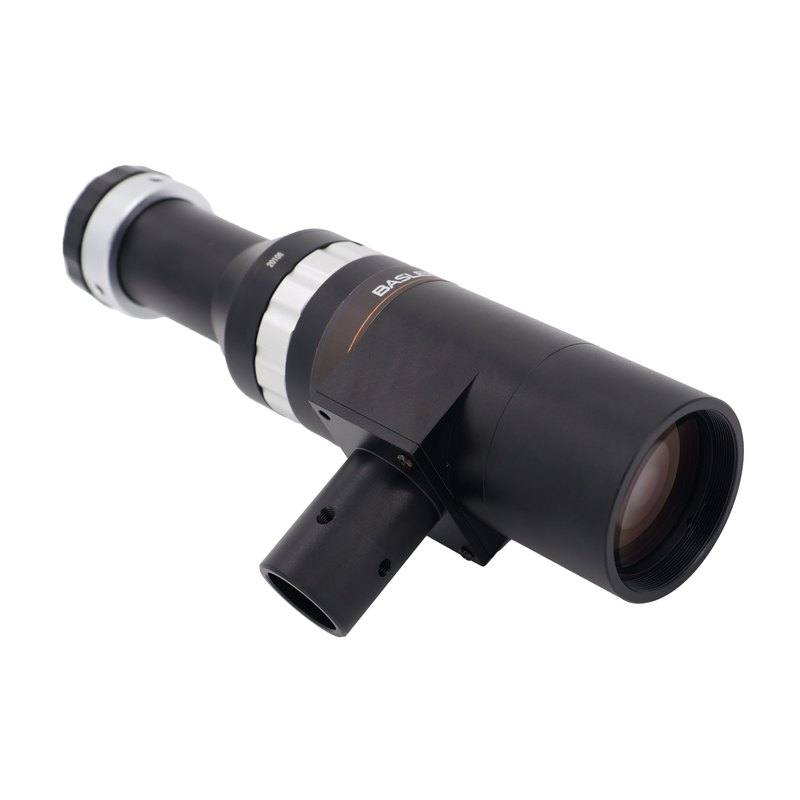
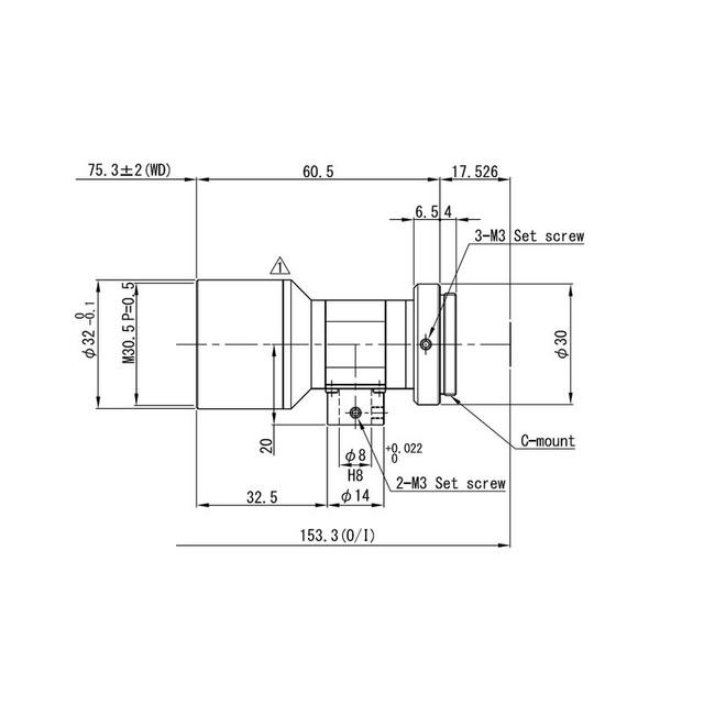
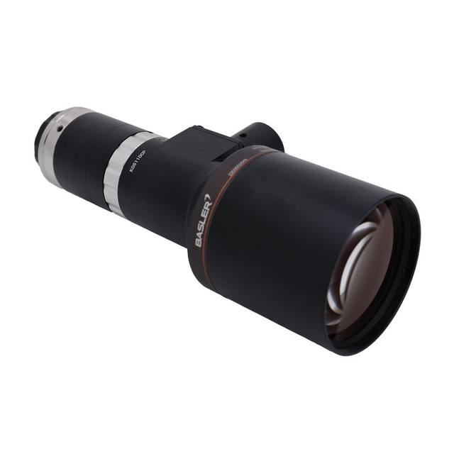
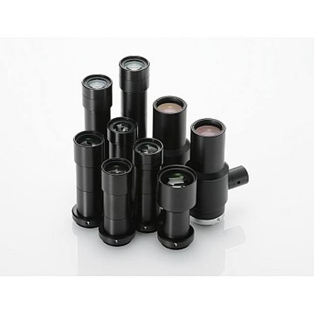
The C23T-2-110-VI-C is a single-sided object-space telecentric C-mount lens designed for precise industrial measurement applications. At 2.0x magnification and 108 mm working distance, it delivers an object-side resolution of 3.8–16.2 µm (dependent on aperture F10.6–F45) and MTF30 performance of 62–22 lp/mm. The 11 mm image circle covers sensors up to 2/3", with an image-side distortion of only 0.08% max and object-side telecentricity of 0.01° max. An integrated coaxial illumination port allows connection of an external light source for homogeneous, shadow-free illumination of specular or structured surfaces.
The Basler C23T-2-110-VI-C is a single-sided, object-space telecentric C-mount lens built around a fixed 2.0x magnification and a precisely controlled 108 mm working distance. Telecentricity — measured at 0.01° maximum on the object side — means chief rays travel parallel to the optical axis across the entire field, so the apparent size of a part does not change even if it shifts slightly toward or away from the lens. For dimensional gauging, this eliminates the perspective-induced measurement error that plagues conventional lenses, making the optic directly suitable for applications where a change of ±1–2 mm in object-to-lens distance would otherwise produce a measurable size error. The 108 mm working distance is a practical number for integrating guards, illumination hardware, or air-blow fixtures between the part and the lens without compromising measurement integrity.
The 11 mm image circle covers sensors up to the 2/3" format, and the variable iris range of F10.6–F45 gives the integrator direct control over depth of field and resolution. At F10.6 (maximum aperture) object-side resolution reaches 3.8 µm and MTF30 performance sits at 62 lp/mm — the sharpest end of the lens's operating envelope and the right setting when fine surface features or narrow features must be resolved. Stopping down to F45 relaxes resolution to 16.2 µm / 22 lp/mm but maximises depth of field, which matters when parts have a defined height variation or when the inspection plane cannot be guaranteed perfectly flat. Image-side distortion is held to 0.08% maximum across the full 11 mm image circle, meaning a 10 mm feature at the edge of the field is rendered with less than 8 µm of positional error — a level of geometric fidelity that supports sub-pixel measurement without software distortion correction consuming computational budget.
The integrated coaxial illumination port is a defining design feature for surface and measurement work. By introducing light collinearly along the optical axis through a beamsplitter, coaxial illumination produces a near-specular reflection pattern that makes flat, reflective, or structured surfaces appear uniformly bright while any surface tilt or raised feature appears dark. This is the optimal illumination geometry for detecting scratches on polished metal, inspecting solder joints, reading engraved or embossed date codes on packaging, or gauging etched features on silicon wafers — all scenarios where side-lit or diffuse illumination creates shadows that confuse edge-detection algorithms. The C-mount interface keeps the lens compatible with the broad installed base of 2/3" area-scan cameras from Basler and other GigE, USB3, or CoaXPress platforms.
Best for
Precision dimensional gauging of machined or stamped parts where telecentricity is required to eliminate parallax-induced measurement error at 108 mm working distance
Surface defect inspection of polished, reflective, or specular components — metals, ceramics, or coated surfaces — using the integrated coaxial illumination port for shadow-free, uniform brightfield imaging
Electronics and semiconductor inspection of PCB pads, solder joints, wafer features, or chip surfaces where 3.8 µm object-side resolution at F10.6 is needed to resolve fine structures across a 2/3" sensor
Pharmaceutical and medical-device packaging inspection combining 0.08% maximum distortion for accurate feature placement verification with adjustable depth of field via the F10.6–F45 iris range
OCR/OCV on engraved, embossed, or laser-marked codes on packaging or components, where coaxial illumination makes recessed characters appear with maximum contrast against a bright background
Selection notes
Sensor format compatibility: the 11 mm image circle covers 2/3" sensors only. Using this lens on a 1" or larger sensor will cause corner vignetting and loss of resolution at the field edges — confirm your camera's sensor diagonal before ordering.
Working distance is fixed at 108 mm and magnification is fixed at 2.0x. Unlike zoom or variable-magnification lenses, the object field of view is determined solely by your camera sensor size. For a 2/3" sensor (8.8 × 6.6 mm active area), the imaged object field is approximately 4.4 × 3.3 mm. Verify this field of view covers the required inspection area before committing to the optical design.
The variable iris (F10.6–F45) requires an explicit aperture decision during system qualification. At F10.6 you get 3.8 µm resolution and a shallow depth of field; at F45 you gain depth of field but resolution degrades to 16.2 µm. For measurement-critical applications, select the aperture during calibration and lock it — do not leave it adjustable in a production environment.
The integrated coaxial illumination port requires a compatible external light source; it is not self-illuminating. The port accepts an external coaxial light module and acts as the coupling point. Confirm the illumination source's connector and spectral output are matched to your camera's sensor sensitivity (monochrome vs. colour) and any optical filter in the system.
C-mount thread engagement depth matters for telecentric lenses. Non-standard C-mount adapters or cameras with a flange-focal distance outside the C-mount specification (17.526 mm) will shift the working distance away from 108 mm and degrade telecentricity. Use cameras with a certified C-mount flange distance or compensate with a precision spacer.
Specifications: General
Brand
Basler
Specifications: Optical
Lens mount
C-mount
Magnification
2.0x
Working distance
108 mm
Aperture (f-number)
F10.6–F45
Image circle / max sensor
11 mm (2/3" format)
Telecentric
Yes — object-side telecentric
Optical resolution
3.8–16.2 µm object-side resolution (dep. on f/#)
Applications this camera is commonly selected for. Open one to see the full recommended hardware and approach.
Matched automatically by: camera mount fits the lens mount · camera sensor is covered by the lens image circle — this lens: C-mount · 11 mm (2/3" format) image circle.
By category
All 758Area scan cameras 622High-speed cameras 108High-resolution cameras 28
By brand
All 758Omron / Sentech 297Basler 242iRAYPLE 200Datalogic / Datasensing 19
Get a first image quickly with the pylon Viewer, then move into the pylon SDK for your application. These cameras are GenICam/GenTL-compliant, so any compliant vision software can drive them as well.
Download and install the pylon Camera Software Suite for your OS from Basler. This provides the pylon Viewer, the GenTL transport-layer producers and the pylon SDK (C/C++/.NET/Python). On Windows the installer adds the needed drivers; on Linux follow the included setup notes for USB and network permissions.
2. Connect the camera and check the link
Cable the camera to its matching interface: GigE Vision to a GigE port (use a quality cable and, ideally, a dedicated NIC with jumbo frames enabled), USB3 Vision to a USB 3.x port with the supplied cable, or CoaXPress to the frame grabber. Provide power where required (PoE, USB bus power, or PoCXP). Open the pylon Viewer and confirm the camera appears in the device list; for GigE, make sure the camera and NIC are on the same subnet.
3. Grab a first image and set exposure, gain and pixel format
Select the camera in the pylon Viewer and start a continuous grab. Adjust exposure time and gain until the image is well exposed (avoid clipped highlights), set the pixel format (e.g. Mono8 or a Bayer/RGB format), and focus the lens. Use a test pattern if the lens or scene is not ready yet.
4. Configure triggering and acquisition
Decide between free-run and triggered acquisition. For synchronized capture, set the trigger source (software or a hardware line on the I/O connector), trigger mode and any debounce or exposure mode, then verify timing. Note the parameter names you change in the Viewer feature tree, as you will reuse them in code.
5. Move to the SDK or a GenICam-compliant library
Recreate your settings in code with the pylon SDK (C, C++, .NET or Python) to open the device, apply the same features and pull frames into your pipeline; pylon vTools and pylon AI can add processing blocks. Because the cameras are GenICam/GenTL standard, third-party vision libraries work too. Once the image stream is stable, you can route frames to a deep-learning inspection such as Rosepetal for automated defect detection.
Frequently asked questions
At 2.0x fixed magnification on a 2/3" sensor (nominal active area 8.8 × 6.6 mm), the imaged object field is approximately 4.4 × 3.3 mm. The 11 mm image circle covers the full 2/3" diagonal so the entire sensor area is usable without vignetting.
Yes — the 11 mm image circle fully covers any sensor smaller than 2/3". On a 1/2" sensor the field of view will simply be smaller (the lens images a narrower object field), which can be advantageous for higher pixel density over a small part. There is no image quality penalty from using a smaller sensor inside the 11 mm circle.
The specs define the resolution extremes (3.8 µm at F10.6, 16.2 µm at F45) which directly reflect depth-of-field and diffraction trade-offs. Stopping down to F45 significantly extends depth of field — useful for parts with height variation — at the cost of resolving power dropping to 16.2 µm object-side. For sub-10 µm resolution, stay at or near F10.6.
The lens has an integrated coaxial illumination port that accepts an external light source via the built-in coupling; no illuminator is included in the lens package. A coaxial ring light or fibre-optic coaxial illuminator designed for the port geometry must be sourced separately and matched to the port's coupling interface. The coaxial design produces on-axis, shadow-free brightfield illumination — ideal for specular or structured surfaces.
Maximum image-side distortion is 0.08% across the full 11 mm image circle. At 0.08%, a feature 5 mm from the optical axis has a worst-case positional error of approximately 4 µm at the image plane (scaled to object space at 2.0x: ~2 µm). For most dimensional gauging applications this is below the sub-pixel noise floor and does not require software distortion correction, simplifying calibration and runtime computation.