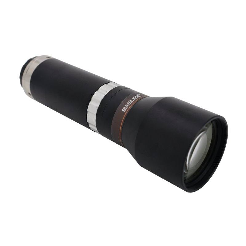
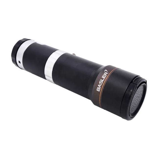
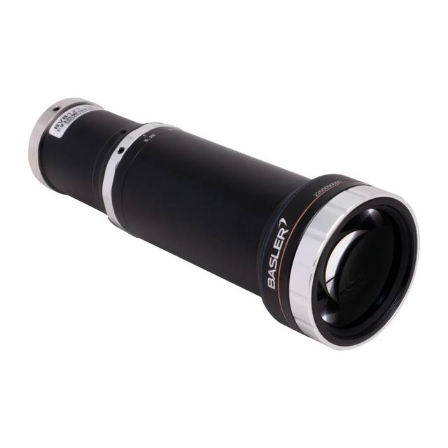
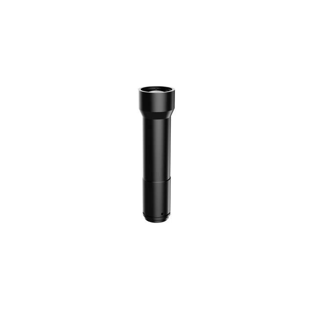
The Basler C11T-1-110-VI is a single-sided object-space telecentric lens with a fixed 1.0x magnification and a 110 ±2 mm working distance, covering sensors up to 1.1" (18.4 mm image circle). Its aperture range of F7–F32 yields a theoretical object-side resolution of 4.7–21.5 µm and MTF30 performance of 128–31 lp/mm respectively. Image-side distortion is kept to a maximum of 0.1% (typical) and object-side telecentricity is 0.06° max (typical), making it suitable for dimensional measurement and defect inspection tasks. The lens features a metal housing, manual variable iris, C-mount interface, and a total length of 142.6 mm.
The Basler C11T-1-110-VI is a single-sided object-space telecentric C-mount lens operating at a fixed 1.0x magnification with a 110 ±2 mm working distance. Its 18.4 mm image circle covers sensors up to 1.1", making it compatible with the largest area-scan sensors in the C-mount ecosystem. Telecentricity is the defining optical property here: with object-side telecentricity held to a maximum of 0.06° (typical), the principal ray exits the object plane nearly parallel to the optical axis regardless of where it strikes the field. This eliminates parallax error — the measurement-distorting artefact caused by perspective projection in conventional lenses — so the apparent size of a part does not change as it moves axially within the working distance tolerance. For any application where you are comparing a pixel count to a real-world dimension, this property is not optional; it is the foundation of measurement traceability.
Distortion is held to a maximum of 0.1% (typical), which at 1.0x magnification means a 10 mm feature will be rendered on-sensor within 10 µm of its true position across the full image circle. The aperture range of F7–F32 gives installers control over two competing demands: at F7 the theoretical object-side resolution reaches 4.7 µm with MTF30 performance of 128 lp/mm, while stopping down toward F32 reduces resolving power to 21.5 µm / 31 lp/mm at the benefit of extended depth of field and greater tolerance for part height variation. Choosing the working aperture is therefore a direct trade-off between resolving the finest feature you need to capture and how much axial variation your part fixtures allow. The manual variable iris means this decision is made at commissioning time and locked in — there is no electronic iris control to introduce variability between frames.
The lens ships in an all-metal housing measuring 142.6 mm in total length and terminates in a standard C-mount thread. Because the working distance is fixed at 110 ±2 mm, the mechanical installation must hold that standoff consistently; stage-based systems and fixed-mount conveyors suit this lens far better than hand-held or variable-distance setups. The C-mount interface is universal across the major GigE, USB3 Vision, and CoaXPress area-scan cameras with 1.1" or smaller sensors, so the lens does not constrain interface selection. For lighting, coaxial or on-axis illumination (ring or diffuse dome) is strongly preferred with telecentric optics because off-axis illumination can cast shadows that vary across the flat telecentric field in ways that undermine edge-detection accuracy.
Best for
Dimensional gauging of precision machined or stamped parts where sub-pixel measurement accuracy is required and part height variation must not introduce magnification error
Semiconductor and electronics inspection tasks such as die-attach offset measurement, solder-ball pitch verification, or PCB pad registration where tolerances are in the tens of micrometres
Pharmaceutical tablet and capsule dimensional compliance checks on high-throughput conveyors where consistent working distance can be maintained by a fixed-height guide rail
Medical-device component inspection requiring traceable dimensional data — implant profiles, seal geometry, connector pin pitch — where image distortion must be demonstrably below 0.1%
Automotive stamped or sintered metal part gauging at a fixed inspection station, particularly where 3D step features or height differences would cause parallax error in a conventional entocentric lens
Selection notes
Working distance is fixed at 110 ±2 mm with no focus adjustment; your mechanical fixture must hold the part surface within that ±2 mm tolerance, and stage travel or conveyor height variation must be budgeted against this window before committing to the lens
The 18.4 mm image circle fills 1.1" sensors completely; if you are pairing with a smaller sensor (e.g., 1", 2/3") the effective field of view narrows proportionally and the full image circle is not used — verify your required field of view against the camera's physical sensor size, not the lens image circle alone
At 1.0x magnification the object field equals the sensor's active area exactly, so confirm the largest part feature to be measured fits within that area at your target resolution — a 1.1" sensor's active area sets the maximum measurable field
Aperture selection at commissioning is a one-time trade-off: use the widest aperture (F7) for maximum resolving power of 4.7 µm when part surfaces are flat and well-fixtured; stop down toward F32 only when part height variation requires extended depth of field, accepting a reduced resolution of 21.5 µm
Avoid adding spacer rings or adapters between the lens and camera body: any extension shifts the working distance away from the specified 110 ±2 mm and invalidates the telecentric calibration — use a camera body with a correctly toleranced C-mount flange
Specifications: General
Brand
Basler
Specifications: Optical
Lens mount
C-mount
Aperture (f-number)
F7–F32
Image circle / max sensor
18.4 mm (1.1")
Telecentric
Yes
Magnification
1.0x
Working distance
110 ±2 mm
Specifications: Mechanical
Housing material
Metal
Applications this camera is commonly selected for. Open one to see the full recommended hardware and approach.
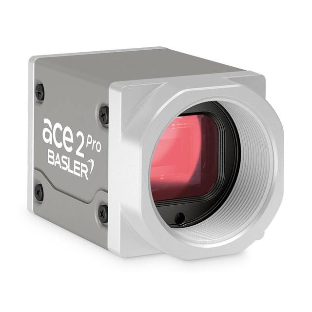
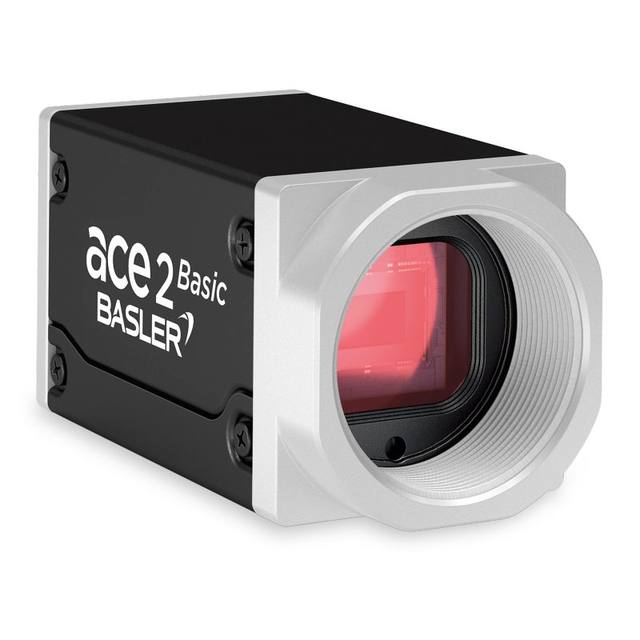
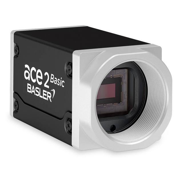
Matched automatically by: camera mount fits the lens mount · camera sensor is covered by the lens image circle — this lens: C-mount · 18.4 mm (1.1") image circle.
Get a first image quickly with the pylon Viewer, then move into the pylon SDK for your application. These cameras are GenICam/GenTL-compliant, so any compliant vision software can drive them as well.
Download and install the pylon Camera Software Suite for your OS from Basler. This provides the pylon Viewer, the GenTL transport-layer producers and the pylon SDK (C/C++/.NET/Python). On Windows the installer adds the needed drivers; on Linux follow the included setup notes for USB and network permissions.
2. Connect the camera and check the link
Cable the camera to its matching interface: GigE Vision to a GigE port (use a quality cable and, ideally, a dedicated NIC with jumbo frames enabled), USB3 Vision to a USB 3.x port with the supplied cable, or CoaXPress to the frame grabber. Provide power where required (PoE, USB bus power, or PoCXP). Open the pylon Viewer and confirm the camera appears in the device list; for GigE, make sure the camera and NIC are on the same subnet.
3. Grab a first image and set exposure, gain and pixel format
Select the camera in the pylon Viewer and start a continuous grab. Adjust exposure time and gain until the image is well exposed (avoid clipped highlights), set the pixel format (e.g. Mono8 or a Bayer/RGB format), and focus the lens. Use a test pattern if the lens or scene is not ready yet.
4. Configure triggering and acquisition
Decide between free-run and triggered acquisition. For synchronized capture, set the trigger source (software or a hardware line on the I/O connector), trigger mode and any debounce or exposure mode, then verify timing. Note the parameter names you change in the Viewer feature tree, as you will reuse them in code.
5. Move to the SDK or a GenICam-compliant library
Recreate your settings in code with the pylon SDK (C, C++, .NET or Python) to open the device, apply the same features and pull frames into your pipeline; pylon vTools and pylon AI can add processing blocks. Because the cameras are GenICam/GenTL standard, third-party vision libraries work too. Once the image stream is stable, you can route frames to a deep-learning inspection such as Rosepetal for automated defect detection.
Frequently asked questions
Yes. The 18.4 mm image circle covers sensors up to 1.1", so a 1" sensor is fully covered. The object field will be smaller than with a 1.1" sensor, scaled to the active sensor dimensions, but the telecentric and distortion specifications still apply across the illuminated image circle.
Distortion is specified at a maximum of 0.1% (typical). At 1.0x magnification this corresponds to a maximum positional error of 1 µm per mm of distance from the optical axis — for example, a feature 5 mm from the centre of the field could be displaced by up to 5 µm. In practice typical performance is better than the published maximum.
No. Both the magnification (1.0x fixed) and the working distance (110 ±2 mm) are fixed. There is no focus ring and no zoom mechanism. The only mechanical adjustment available is the manual variable iris, which controls aperture between F7 and F32.
The highest object-side resolution of 4.7 µm and MTF30 performance of 128 lp/mm are achieved at the widest aperture, F7. Stopping down increases depth of field but reduces resolving power — at F32 the theoretical resolution is 21.5 µm and MTF30 drops to 31 lp/mm. Use F7 unless part height variation requires extended depth of field.
Coaxial or diffuse on-axis illumination is strongly preferred. Because the lens accepts only rays travelling parallel to the optical axis (the defining property of single-sided telecentricity), off-axis light sources produce shadows whose geometry changes across the field, which degrades the edge sharpness that dimensional measurement depends on. Ring lights, on-axis coaxial illuminators, or diffuse dome lights positioned on-axis are the standard pairing.