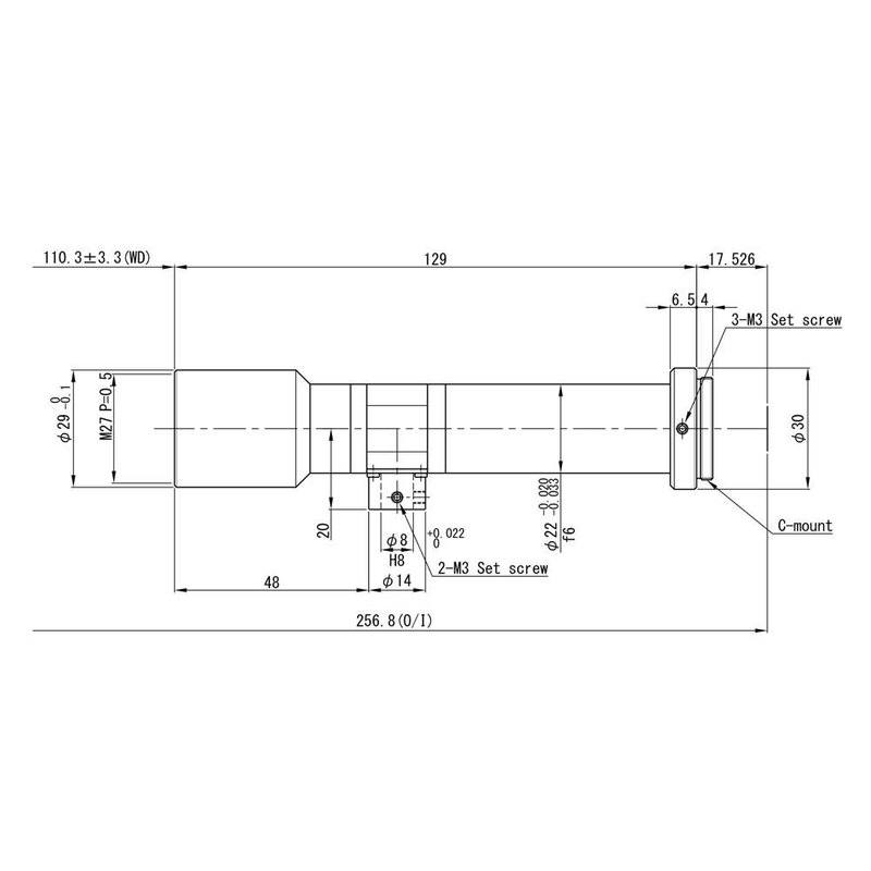
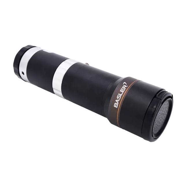
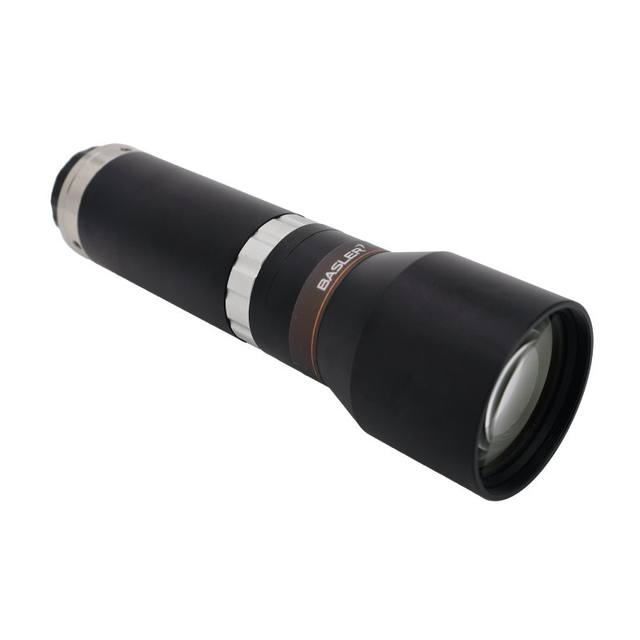
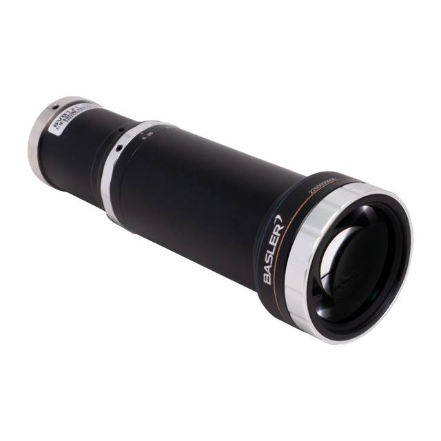
The VS-TCH1-110CO-O is a fixed-magnification (1.0x ±5%) bi-telecentric lens from Omron's VS-TCH high-resolution series, offering a 110.3 mm working distance with a built-in coaxial prism for co-axial illumination. It achieves a numerical aperture of 0.048 (working F/10.5), 0.8 mm depth of field, and an extremely low TV distortion of 0.02% on a 2/3" sensor, making it suitable for high-precision dimensional measurement and alignment. The C-mount interface with a 17.526 mm flange-back distance is compatible with standard machine-vision cameras up to 2/3" format, delivering a 8.4 × 7.1 mm field of view on that sensor size. Physical footprint is compact at φ30 × 129 mm, with a filter thread of M27 P=0.5 and approximate weight of 96 g.
The VS-TCH1-110CO-O is a fixed-magnification bi-telecentric lens operating at a true 1.0x (±5%) magnification ratio, which means one pixel on the sensor corresponds to one pixel of real-world feature size across the entire 8.4 × 7.1 mm field on a 2/3" sensor. Telecentricity in both the object and image spaces eliminates the perspective error that causes conventional lenses to report a slightly different diameter for a raised feature versus a recessed one — a critical property whenever the installation cannot guarantee that every part arrives at exactly the same standoff height. At 110.3 mm working distance the lens provides enough clearance for most in-line gauging fixtures, robot-end-effector mounts, or conveyor-edge setups, while the compact ø30 × 129 mm body and 96 g mass keep cantilever stress on the camera low. The C-mount flange-back of 17.526 mm is standard, so no adapter ring is required for any C-mount industrial camera up to 2/3" format.
The optical design delivers TV distortion of just 0.02%, which is among the lowest values achievable at this price tier. In practical terms, on a 2/3" sensor a 0.02% distortion figure means a feature at the edge of the field is displaced by below 1 µm — effectively negligible relative to any real pixel pitch at 2 MP or above. Working aperture is F/10.5 (NA 0.048), yielding a depth of field of 0.8 mm. That 0.8 mm DOF demands careful z-axis fixturing; it also means the system is unforgiving of part tilt or vibration, so rigid mounting and stable transport are prerequisites. The built-in coaxial prism port is the defining feature of this particular variant: it accepts a coaxial illuminator that injects light along the optical axis and reflects it toward the object, then allows return light to pass straight through to the sensor. This geometry produces a bright, shadow-free, mirror-like reflection off flat specular surfaces — ideal for reading laser-marked or dot-peened codes on polished metal and for detecting micro-scratches that scatter the coaxial beam differently than the surrounding surface.
For camera pairing, any C-mount sensor up to 2/3" is mechanically compatible, but the lens is specified for up to 2 MP optical resolution, so pairing it with a sensor denser than roughly 1600 × 1200 pixels at 2/3" format may not yield additional spatial detail — choose a camera whose pixel pitch at that format is at or above the diffraction limit at F/10.5. The M27 P=0.5 filter thread accepts standard 27 mm optical filters; a bandpass filter matched to the coaxial illuminator's wavelength is a common addition to reject ambient light on factory floors. Because magnification is fixed, field of view is determined solely by sensor size: 8.4 × 7.1 mm on 2/3". Engineers sizing the system should confirm that the largest expected part feature spans no more than roughly 8 mm, or plan a multi-shot tiling strategy.
Best for
High-precision dimensional gauging of machined or stamped parts where feature heights vary by up to ±0.4 mm (within the 0.8 mm depth of field) and sub-pixel measurement accuracy is required — the 0.02% distortion and 1.0x magnification make sub-micron per-pixel calibration traceable and stable.
Reading laser-marked DataMatrix or 2D codes on polished or brushed metal surfaces (electronics, automotive, medical implants) where ring or dome lighting creates specular hot-spots — the integrated coaxial prism port delivers uniform on-axis illumination that maximises contrast on these low-relief marks.
Wafer-level or PCB component alignment and placement verification in semiconductor and electronics assembly, where parallel ray geometry ensures that positional readings are independent of component thickness variation across the carrier.
Surface micro-defect detection on flat reflective targets such as glass, ceramic, or mirror-finished metal where coaxial illumination reveals pits, scratches, and inclusions as dark features against a uniform bright background.
Medical device and pharmaceutical blister-pack inspection requiring traceable dimensional data with minimal lens-induced measurement error, especially in regulated environments where the 0.02% distortion figure can be cited directly in system validation documentation.
Selection notes
Depth of field is only 0.8 mm — fixtures and part presentation must hold z-axis variation within ±0.4 mm of the nominal working distance of 110.3 mm; free-resting or vibrating parts will produce out-of-focus images that invalidate measurements.
The coaxial prism port is only useful when paired with a compatible coaxial illuminator; the illuminator is not included and must be specified separately — confirm beam size, wavelength, and port diameter compatibility before ordering. A bandpass filter on the M27 P=0.5 filter thread is strongly recommended to suppress ambient and ring-light contamination.
Camera sensor format must not exceed 2/3" (8.8 mm diagonal) — using a larger sensor will vignette the corners and introduce uncalibrated edge distortion. Pixel pitch should ideally be 3.45 µm or coarser to stay within the diffraction-limited resolution at F/10.5.
Magnification is fixed at 1.0x with no focus or zoom adjustment; the field of view is entirely determined by sensor size (8.4 × 7.1 mm on 2/3"). If the inspection window needs to change, a different sensor format or a different lens from the VS-TCH series must be selected — there is no in-field adjustment.
The 129 mm body length combined with the 110.3 mm working distance places the part approximately 239 mm from the lens flange; verify this clearance envelope is available in the machine frame, especially in gantry or pick-and-place installations.
Specifications: General
Brand
VS-Technology (sold by Omron as OEM)
Specifications: Optical
Lens mount
C-Mount
Magnification
1.0x
Working distance
110.3 mm
Aperture (f-number)
F10.49
Image circle / max sensor
2/3" (8.8 mm diagonal)
Telecentric
Yes
Optical resolution
2 MP
Specifications: Mechanical
Weight
96 g
Dimensions
φ30 mm (max.) × L=129 mm
Applications this camera is commonly selected for. Open one to see the full recommended hardware and approach.
Matched automatically by: camera mount fits the lens mount · camera sensor is covered by the lens image circle — this lens: C-Mount · 2/3" (8.8 mm diagonal) image circle.
By category
All 758Area scan cameras 622High-speed cameras 108High-resolution cameras 28
By brand
All 758Omron / Sentech 297Basler 242iRAYPLE 200Datalogic / Datasensing 19
These steps take an Omron Sentech (STC) camera from the box to a stable first image and on to your own application. They apply across the GigE Vision, USB3 Vision and CoaXPress STC families; the interface only changes how you cable and power the camera.
Download and install the Sentech SDK on the host PC. The package provides StViewer, the viewing and configuration software you use to bring the camera up, and StApi, the programming SDK you integrate later. Because the cameras are GenICam/GenTL-compliant, StApi also registers a GenTL producer, so any GenICam-compliant third-party vision software can discover and drive the camera as an alternative front end.
2. Cable, power and connect the camera
Connect according to the interface. GigE Vision: link to a Gigabit NIC (use PoE or the separate power input) and put the camera and host on the same subnet; for USB3 Vision use a USB 3.x port and a certified cable; for CoaXPress (STC) connect to a CoaXPress frame grabber, which also supplies Power-over-Coax. Then open StViewer and let it enumerate the camera. If a GigE camera does not appear, check the IP configuration and firewall, and on USB3 confirm the host bandwidth and driver.
3. Configure exposure, gain and white balance
Open the device in StViewer and start a live stream. Set exposure and gain for a well-exposed, low-noise image: raise exposure first and only add gain when more light or a faster shutter is not an option, keeping exposure short enough to freeze motion on global-shutter models. On colour cameras, run white balance under your actual production lighting. Adjust the lens aperture and focus on a representative target before tuning anything else.
4. Set the trigger and grab a first image
Start in free-run (continuous) acquisition to confirm a clean, stable image. For inline inspection switch to hardware or software triggering: select the trigger source, set the active edge and any delay, and wire the strobe or illumination to the camera's I/O so lighting fires with each exposure. Acquire and save a frame in StViewer; this saved image is your reference for the SDK stage and for downstream inspection.
5. Move to the StApi SDK (or any GenICam software)
Once the image is stable, reproduce the same settings in code. Use StApi to open the device, apply the GenICam features you validated in StViewer (exposure, gain, trigger, pixel format) and grab frames into your application via the bundled C++, C, C#/.NET or Python interfaces; the included samples are the fastest starting point. Prefer a different stack? The same GenICam/GenTL camera works with third-party vision libraries. With a reliable feed, you can route it into a deep-learning inspection such as Rosepetal for AI-based defect detection.
Frequently asked questions
The lens uses a standard C-mount interface with a 17.526 mm flange-back distance and is designed for sensors up to 2/3" format (8.8 mm diagonal). Any C-mount industrial camera with a sensor at or smaller than 2/3" is mechanically and optically compatible. Using a camera with a larger sensor will cause vignetting at the image corners.
At 1.0x magnification on a 2/3" sensor the field of view is 8.4 × 7.1 mm. Magnification is fixed — there is no zoom or focus ring. The only way to change the field of view is to use a different sensor format or select a different lens with a different fixed magnification.
The depth of field is 0.8 mm, meaning parts must remain within ±0.4 mm of the 110.3 mm nominal working distance to stay in acceptable focus. Beyond that range the image blurs, which degrades both measurement accuracy and code-reading reliability. Rigid fixturing is essential.
The lens features a built-in coaxial prism port designed to accept a coaxial illuminator, but no illuminator is included in the lens package. The illuminator must be purchased separately; buyers should verify that the chosen illuminator's beam diameter, wavelength, and mechanical interface match the lens port specification before ordering.
TV distortion is 0.02%, which means geometric measurement errors introduced by the lens alone are below 1 µm across the 8.4 × 7.1 mm field on a 2/3" sensor. This is important in dimensional gauging because higher distortion values would require software correction that itself introduces calibration uncertainty; at 0.02% the distortion contribution to measurement error is negligible for most precision applications.