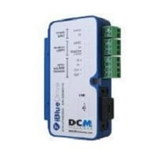
The FLV-TCC3HB is a compact, camera-mounted lighting controller for Omron FLV-series LED lighting, used with FH/FZ5 vision controllers and FH-S/FZ-S cameras. It controls three channels: a 0ch spot light using a constant-current drive and two standard lights (1ch/2ch) using a constant-voltage drive, supporting both trigger (strobe) and continuous lighting. Light intensity is set on the image sensor controller via duty (PWM, 100 kHz, 255 levels) or voltage/current adjustment (255 levels). It is powered from the camera (12 V) or an external 24 VDC supply, draws up to 1.5 A, and is rated IP20 in an aluminum case weighing about 130 g including the camera-mount plate.
Brand
Omron / Sentech
Lighting type
Spot + standard light controller (1 spot + 2 standard channels)
Mode
Trigger (strobe) and continuous lighting
Controller required
Is the controller (used with FH/FZ5 image sensor controller and FH-S/FZ-S camera)
The Omron FLV-TCC3HB is not a light or a camera but the three-channel driver that sits between them: a compact, camera-mounted controller for Omron FLV-series LED lighting, designed to work with FH/FZ5 image sensor controllers and FH-S/FZ-S cameras. It exposes one spot-light channel (0ch) driven with a constant-current circuit and two standard-light channels (1ch and 2ch) driven with constant voltage. That split matters in practice: constant-current drive on the spot channel holds LED output stable as the diode warms or ages, which is what you want for a high-intensity coaxial or spot illuminator where brightness repeatability feeds directly into grey-level thresholds; the constant-voltage channels handle bar, ring or dome standard lights where absolute current matching is less critical. Intensity for all channels is set from the image sensor controller, not on the box, using either PWM duty (100 kHz, 255 levels) or voltage/current adjustment across 255 levels, so light setup lives in the same FH/FZ recipe as the rest of the inspection and travels with the job.
Because it supports both trigger (strobe) and continuous lighting, the FLV-TCC3HB lets one hardware setup serve both stationary and moving-part inspection. In strobe mode the controller overdrives the LEDs in sync with the camera trigger to freeze motion and lift contrast for the brief exposure, which is the right choice on indexing tables, conveyors and any line where ambient light or part movement would otherwise wash out the image; in continuous mode it behaves as a steady source for static stations or setup and alignment. The 100 kHz PWM means dimming happens far faster than typical machine-vision exposure times, so you do not see brightness banding tied to the duty cycle within a single frame. Power can come from the camera at 12 V or from an external 24 VDC +/-10% supply (including ripple), and the channel you choose has a direct ceiling: the controller draws up to 15 W of lighting power on 24 V external trigger lighting but only up to 7.5 W on 12 V continuous from the camera, with total current up to 1.5 A. That is the single most important number when you size your light load.
Physically it is built to ride on the camera. The case and camera-mount plate are aluminum (the cable is PVC), it weighs about 130 g including the mount plate, and it connects to the camera with a dedicated cable wired directly to the main unit rather than over a fieldbus or M12 network. The aluminum case helps shed the heat that a 15 W high-brightness driver generates, but the IP20 rating tells you this is a panel- or enclosure-grade device with no protection against water or fine dust ingress, so it belongs inside a sealed camera housing or a clean cell rather than out in an open washdown line. Operating range is 0 to +50 C (storage -15 to +60 C) with no icing or condensation, which covers typical indoor factory floors but rules out cold-store or high-heat oven-adjacent placement without conditioning.
Best for
Driving a high-brightness FLV spot light plus two standard bar or ring lights from a single camera-mounted unit on an Omron FH/FZ5 inspection station, keeping all three light channels in one recipe
Strobed inspection of moving or indexed parts on conveyors and rotary tables, where the 100 kHz PWM overdrive freezes motion and lifts contrast for short camera exposures
Surface and defect inspection where the constant-current 0ch spot channel gives repeatable, drift-free brightness for stable grey-level thresholding
OCR/OCV and code traceability reading where lighting intensity must be set and recalled per job from the FH/FZ image sensor controller rather than trimmed by hand on the device
Space-constrained cells that need lighting drive mounted directly on the camera (about 130 g, aluminum case) instead of a separate DIN-rail controller
Selection notes
Confirm the host: this is the controller for an Omron FLV lighting + FH/FZ5 controller + FH-S/FZ-S camera system. It is not a standalone driver for third-party lights and has no use without those Omron components.
Size your light load to the power budget before specifying channels. The unit allows up to 15 W only on 24 V external trigger lighting; on 12 V camera power in continuous mode the ceiling drops to 7.5 W, with total current up to 1.5 A. A bright spot plus two standard lights can exceed the 12 V budget, forcing the external 24 VDC supply.
Provide a clean 24 VDC +/-10% supply (ripple included in that tolerance) if you intend to run trigger lighting at full power, and plan the wiring run for the dedicated camera connection cable that lands directly on the main unit.
Plan for IP20: there is no ingress protection, so the controller must live inside a sealed camera enclosure or a clean cabinet, not in a washdown, misting or dusty open-line position.
Respect the 0 to +50 C operating window and the no-condensation requirement. A 15 W driver in a closed housing adds heat, so allow for the aluminum case to dissipate it and avoid stacking it against other hot components.
Match drive type to the light: use the constant-current 0ch channel for the spot light that needs brightness repeatability, and the constant-voltage 1ch/2ch channels for the standard lights.
Specifications: General
Brand
Omron / Sentech
Lighting type
Spot + standard light controller (1 spot + 2 standard channels)
Specifications: Interface
Connection
Camera connection cable, directly connected to the main unit
Specifications: Electrical
Mode
Trigger (strobe) and continuous lighting
Controller required
Is the controller (used with FH/FZ5 image sensor controller and FH-S/FZ-S camera)
These steps take an Omron Sentech (STC) camera from the box to a stable first image and on to your own application. They apply across the GigE Vision, USB3 Vision and CoaXPress STC families; the interface only changes how you cable and power the camera.
Download and install the Sentech SDK on the host PC. The package provides StViewer, the viewing and configuration software you use to bring the camera up, and StApi, the programming SDK you integrate later. Because the cameras are GenICam/GenTL-compliant, StApi also registers a GenTL producer, so any GenICam-compliant third-party vision software can discover and drive the camera as an alternative front end.
2. Cable, power and connect the camera
Connect according to the interface. GigE Vision: link to a Gigabit NIC (use PoE or the separate power input) and put the camera and host on the same subnet; for USB3 Vision use a USB 3.x port and a certified cable; for CoaXPress (STC) connect to a CoaXPress frame grabber, which also supplies Power-over-Coax. Then open StViewer and let it enumerate the camera. If a GigE camera does not appear, check the IP configuration and firewall, and on USB3 confirm the host bandwidth and driver.
3. Configure exposure, gain and white balance
Open the device in StViewer and start a live stream. Set exposure and gain for a well-exposed, low-noise image: raise exposure first and only add gain when more light or a faster shutter is not an option, keeping exposure short enough to freeze motion on global-shutter models. On colour cameras, run white balance under your actual production lighting. Adjust the lens aperture and focus on a representative target before tuning anything else.
4. Set the trigger and grab a first image
Start in free-run (continuous) acquisition to confirm a clean, stable image. For inline inspection switch to hardware or software triggering: select the trigger source, set the active edge and any delay, and wire the strobe or illumination to the camera's I/O so lighting fires with each exposure. Acquire and save a frame in StViewer; this saved image is your reference for the SDK stage and for downstream inspection.
5. Move to the StApi SDK (or any GenICam software)
Once the image is stable, reproduce the same settings in code. Use StApi to open the device, apply the GenICam features you validated in StViewer (exposure, gain, trigger, pixel format) and grab frames into your application via the bundled C++, C, C#/.NET or Python interfaces; the included samples are the fastest starting point. Prefer a different stack? The same GenICam/GenTL camera works with third-party vision libraries. With a reliable feed, you can route it into a deep-learning inspection such as Rosepetal for AI-based defect detection.
Frequently asked questions
Three channels: one spot light on 0ch driven by constant current, plus two standard lights on 1ch and 2ch driven by constant voltage. It is built for Omron FLV-series LED lighting.
Both. It supports trigger (strobe) lighting synchronized to the camera as well as continuous lighting, so the same unit covers moving and static inspection.
Intensity is set on the image sensor controller (FH/FZ5), not on the box itself, using PWM duty control at 100 kHz with 255 levels or voltage/current adjustment with 255 levels.
It runs from the camera at 12 V or an external 24 VDC +/-10% supply (ripple included). Lighting power is up to 15 W on 24 V external trigger lighting and up to 7.5 W on 12 V continuous, with total current up to 1.5 A.
It is rated IP20 per IEC 60529 (no water or fine-dust protection) in an aluminum case, and operates from 0 to +50 C (storage -15 to +60 C) with no icing or condensation. It belongs inside a sealed housing or clean cabinet.
It connects via a dedicated camera connection cable wired directly to the main unit, mounts on the camera, and weighs about 130 g including the aluminum camera-mount plate.