Omron / Sentech FLV-FB130130 Edge Type Backlight (130×130)
FLV-FB130130
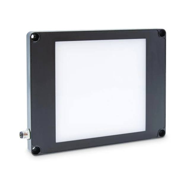
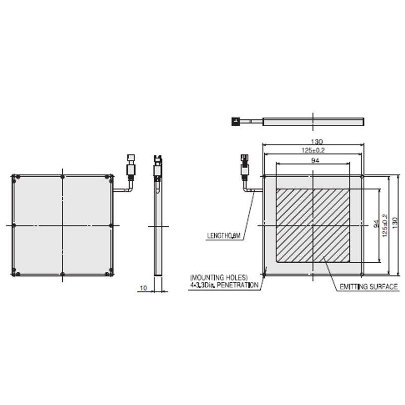
The FLV-FB130130 is an edge-type (side-emitting) backlight in Omron's FLV-FB series, using a light guide and diffusion plate over an LED PCB in an aluminum-alloy case to deliver highly uniform, diffused shadowless backlighting. The unit measures 130×130 mm overall and is only 10 mm thick, with a 94×94 mm lighting area, and weighs about 230 g. It is offered in three color variants (FLV-FB130130W white 5.5 W, FLV-FB130130R red 3.7 W at ~635 nm, FLV-FB130130B blue 5.5 W at ~460 nm). The light is driven through an Omron FLV-TCC or FLV-ATC lighting controller (or an external 24 VDC supply) and mounts via four M3 inserts.
The FLV-FB130130 is an edge-type (side-emitting) LED backlight from Omron's FLV-FB series, built to throw uniform, shadowless transmitted light through a part rather than to illuminate its surface. Internally, an LED PCB sits along the edge of the unit and fires into a light guide; a diffusion plate over that guide spreads the light into an even, glare-free sheet across the 94 x 94 mm emitting area. The 'edge type' construction is what keeps the housing to just 10 mm thick over a 130 x 130 mm footprint, so it slips into tight transport tunnels, under-conveyor gaps, and the underside of XY stages where a thicker direct-lit panel would not physically fit. For an installer, the value of a backlight is geometric: the camera looks straight down through the part at the lit panel, so opaque features read as crisp black silhouettes against a bright, saturated field. That makes edge detection, blob area, and contour measurement far more repeatable than any front-lit approach, because the result depends on the part outline rather than on its surface finish or color.
The unit is offered in three color variants that share the same mechanics but change what the silhouette reveals: white (FLV-FB130130W, 5.5 W) for general-purpose broadband contrast, red (FLV-FB130130R, 3.7 W at ~635 nm), and blue (FLV-FB130130B, 5.5 W at ~460 nm). Wavelength choice matters most when you are imaging through translucent or tinted material or trying to suppress color variation: a monochrome camera paired with the red ~635 nm or blue ~460 nm version can render a part more uniformly than a broadband white field, and red is the lowest-power option at 3.7 W. The white version is the safe default when you do not yet know the part's spectral behavior or you want flexibility across mixed materials. In all three cases the emission is explicitly diffuse and uniform by design, which is the whole point of a backlight: you want flat, even brightness edge-to-edge so that thresholding gives the same silhouette regardless of where the part sits in the 94 x 94 mm window.
Electrically and mechanically the FLV-FB130130 is straightforward to design in. It runs on 24 VDC and is driven through an Omron FLV-TCC or FLV-ATC lighting controller, or from an external 24 VDC supply, via a cable connection to that controller rather than a connector on the panel. The light mode is continuous, controller-driven, so out of the box this is a steady-state illuminator; if your application needs precise strobing or brightness control you get that behavior from the FLV controller, not from the light head itself. The body is an aluminum-alloy case weighing about 230 g, which gives it some thermal mass and rigidity while staying light enough to mount on moving fixtures, and it fastens via four M3 inserts for a simple, repeatable bracket. At 5.5 W (white/blue) or 3.7 W (red) the heat load is modest, so it can sit close to product without a large heatsink, though the aluminum case is doing the dissipation and should not be fully enclosed.
Best for
Silhouette-based dimensional measurement of small opaque parts (connectors, fasteners, stamped or molded components) placed within the 94 x 94 mm field, where the black outline against a bright field gives repeatable edge metrology
Presence/absence and shape verification of components in electronics and semiconductor handling, using the thin 10 mm profile to fit under transport stages and pick-and-place nests
Edge and contour defect inspection on packaging, blister, and film components, where transmitted light exposes gaps, burrs, and missing features as breaks in the silhouette
Through-material imaging of translucent or tinted parts using the red (~635 nm) or blue (~460 nm) variant with a monochrome camera to even out color variation
Backlit OCR/OCV or fill-level type checks where uniform diffuse backlighting on small parts improves character and feature contrast versus front lighting
Selection notes
Size the field to the part: the lighting area is 94 x 94 mm, so the part plus its positional tolerance must stay inside that window with even brightness edge-to-edge; parts larger than ~94 mm will run off the uniform field and lose silhouette accuracy
This is a backlight, not a surface light. It only works when the camera images straight through the part toward the panel, so you must have optical access on the opposite side of the part from the camera; it cannot reveal surface texture, print, or top-face defects
Pick the color deliberately. Red is the lowest-power option (3.7 W) and the ~635 nm or ~460 nm variants pair with a monochrome camera to normalize color, while white (5.5 W) is the broadband default; the choice is fixed per part number, so specify W, R, or B at order time
Plan the controller. The unit is continuous and controller-driven on 24 VDC through an FLV-TCC or FLV-ATC (or an external 24 VDC supply) via cable, so budget for the controller channel and the cable run; strobe and intensity behavior comes from the controller, not the light head
Account for mounting and thermal context: the aluminum-alloy case mounts on four M3 inserts and weighs ~230 g, and the metal body is the heat path at up to 5.5 W, so leave the case exposed enough to dissipate rather than fully boxing it in
These steps take an Omron Sentech (STC) camera from the box to a stable first image and on to your own application. They apply across the GigE Vision, USB3 Vision and CoaXPress STC families; the interface only changes how you cable and power the camera.
Download and install the Sentech SDK on the host PC. The package provides StViewer, the viewing and configuration software you use to bring the camera up, and StApi, the programming SDK you integrate later. Because the cameras are GenICam/GenTL-compliant, StApi also registers a GenTL producer, so any GenICam-compliant third-party vision software can discover and drive the camera as an alternative front end.
2. Cable, power and connect the camera
Connect according to the interface. GigE Vision: link to a Gigabit NIC (use PoE or the separate power input) and put the camera and host on the same subnet; for USB3 Vision use a USB 3.x port and a certified cable; for CoaXPress (STC) connect to a CoaXPress frame grabber, which also supplies Power-over-Coax. Then open StViewer and let it enumerate the camera. If a GigE camera does not appear, check the IP configuration and firewall, and on USB3 confirm the host bandwidth and driver.
3. Configure exposure, gain and white balance
Open the device in StViewer and start a live stream. Set exposure and gain for a well-exposed, low-noise image: raise exposure first and only add gain when more light or a faster shutter is not an option, keeping exposure short enough to freeze motion on global-shutter models. On colour cameras, run white balance under your actual production lighting. Adjust the lens aperture and focus on a representative target before tuning anything else.
4. Set the trigger and grab a first image
Start in free-run (continuous) acquisition to confirm a clean, stable image. For inline inspection switch to hardware or software triggering: select the trigger source, set the active edge and any delay, and wire the strobe or illumination to the camera's I/O so lighting fires with each exposure. Acquire and save a frame in StViewer; this saved image is your reference for the SDK stage and for downstream inspection.
5. Move to the StApi SDK (or any GenICam software)
Once the image is stable, reproduce the same settings in code. Use StApi to open the device, apply the GenICam features you validated in StViewer (exposure, gain, trigger, pixel format) and grab frames into your application via the bundled C++, C, C#/.NET or Python interfaces; the included samples are the fastest starting point. Prefer a different stack? The same GenICam/GenTL camera works with third-party vision libraries. With a reliable feed, you can route it into a deep-learning inspection such as Rosepetal for AI-based defect detection.
Frequently asked questions
The lighting area is 94 x 94 mm within a 130 x 130 mm overall housing. The part plus its placement tolerance should fit inside that 94 x 94 mm uniform field, so it suits small components rather than large panels.
It is an ultrathin edge type backlight, only 10 mm thick over the 130 x 130 mm footprint, weighing about 230 g in an aluminum-alloy case. It mounts via four M3 inserts.
Three variants: white (FLV-FB130130W, 5.5 W), red (FLV-FB130130R, 3.7 W at ~635 nm), and blue (FLV-FB130130B, 5.5 W at ~460 nm). The color is fixed per part number.
Yes. It runs on 24 VDC and is driven through an Omron FLV-TCC or FLV-ATC lighting controller, or an external 24 VDC supply, connected by cable. Its mode is continuous, controller-driven.
It uses an edge LED array with a light guide and diffusion plate to produce highly uniform, diffuse, shadowless backlighting. The camera images through the part, so opaque features appear as crisp silhouettes, which makes edge detection and dimensional measurement more repeatable than surface lighting.