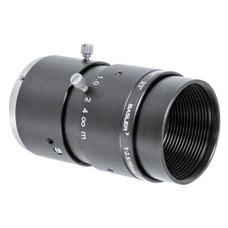
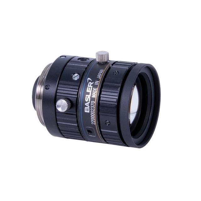
The Basler C23-5026-2M-S is a 49.5 mm (nominal 50 mm) fixed focal length C-mount lens optimized for 2 MP sensors with 5.5 µm pixel pitch, covering an 11 mm image circle (2/3" format). It offers a maximum aperture of F2.6 and stops down to F32, with a focus range from 0.3 m to infinity and an optimum working distance of 1.3 m. Optical distortion is a typical 0.2% pincushion, resolution is specified at 90 LP/mm, and relative illumination is at least 76% at full aperture. The lens operates in the visible spectrum (400–700 nm) and weighs approximately 110 g with an overall optical length of 39 mm.
The Basler C23-5026-2M-S is a fixed 50 mm (true focal length 49.5 mm) C-mount lens engineered specifically for 2 MP machine vision sensors with 5.5 µm pixel pitch, and it covers an 11 mm image circle that fully illuminates 2/3" format sensors. The F2.6 maximum aperture provides a meaningful light-gathering advantage over slower fixed lenses, which matters in continuous-illumination setups where exposure budgets are tight — for example, surface inspection lines running under LED ring lights without strobe overdrive. Stopping down to F32 gives installers substantial depth-of-field headroom when inspection distances vary or when optics need to be locked down for vibration-prone deployments. Manual iris and manual focus controls keep the optical configuration stable: there is no motorised element to drift or require recalibration after a power cycle, a practical advantage in 24/7 production environments.
Optical resolution is specified at 90 LP/mm, which is well matched to a 2 MP sensor at 5.5 µm pixel pitch — the Nyquist limit for that pitch is roughly 91 LP/mm, so the lens is designed to extract essentially all the detail the sensor can capture without over-specifying glass that would go unused. Typical distortion is 0.2% pincushion, a very low figure for a 50 mm C-mount in this price class. That level of distortion is acceptable for most dimensional measurement and code-reading tasks without software correction, though integrators targeting tight gauging tolerances should note the lens is not telecentric — perspective error will appear if the part-to-lens distance varies, so a fixed, well-controlled working distance is important. The minimum focus distance of 0.3 m (optimum 1.3 m) combined with the 50 mm focal length places the typical field of view in a range suitable for component-level inspection at conveyor height rather than microscopic close-up work. Relative illumination of at least 76% across the full image circle at F2.6 means corners are well-lit without stopping down, avoiding vignetting artefacts on large-format 2/3" sensors.
At 110 g and 39 mm optical length, the lens is compact enough to fit inside standard C-mount camera housings. The operating temperature range of -10 to 60 °C covers most factory floor and outdoor-shelter installations without requiring additional thermal management. Because the lens operates in the visible spectrum (400–700 nm), it pairs naturally with visible-spectrum LED illumination and is suited to standard visible-spectrum machine vision sensors; it is not designed for near-infrared work, so installers running NIR illumination schemes should verify spectral transmission before selecting this lens.
Best for
Surface inspection of PCBs, SMD components, and semiconductor wafers at conveyor working distances around 0.3–1.3 m, where the 90 LP/mm resolution fully exploits a 2 MP sensor and the low 0.2% pincushion distortion avoids warping fine-pitch geometry.
Industrial OCR and OCV on pharmaceutical blister packs, labels, and direct-part marks where legibility depends on high contrast and minimal distortion rather than extreme resolution, and where a stable manual-iris setting keeps exposure consistent across production shifts.
Packaging and print inspection tasks — date codes, lot numbers, barcodes, and 2D Data Matrix reads — where the 50 mm focal length gives a comfortable working distance above the line and the F2.6 aperture allows adequate exposure under moderate continuous LED lighting without resorting to high-power strobes.
Robot guidance and pick-and-place alignment in electronics assembly or automotive part handling, where a fixed 50 mm lens on a 2/3" 2 MP camera yields predictable field-of-view geometry that simplifies hand-eye calibration and avoids radial distortion correction steps.
General-purpose dimensional measurement of mid-scale features (not microscopic) where part standoff is fixed and controlled, allowing the non-telecentric 50 mm lens to deliver accurate edge detection without perspective error — provided the measurement plane is held at a consistent distance from the lens.
Selection notes
Sensor format compatibility: the 11 mm image circle covers 2/3" sensors but not larger formats such as 1" or 4/3". Pairing this lens with a camera that has a sensor diagonal exceeding 11 mm will produce heavy vignetting at the corners — verify the sensor format before ordering.
Telecentricity and working distance control: the lens is not telecentric, so any variation in object distance between the lens minimum focus (0.3 m) and the optimum working distance (1.3 m) introduces perspective magnification error. Applications requiring sub-pixel dimensional accuracy must fix the part plane relative to the lens, or apply software correction for any residual perspective shift.
Illumination spectrum: the lens is specified for the visible band (400–700 nm). Installers using near-infrared LED illumination (>800 nm) or UV sources should select a lens with verified NIR or UV transmission rather than assuming this visible-range optic will perform adequately.
Aperture selection trade-off: while F2.6 maximises light throughput, diffraction softening begins to limit resolution as the iris closes toward F32. For inspection tasks that demand full 90 LP/mm sharpness, keep the aperture below F8–F11; reserve the smaller stops for maximising depth of field when resolution is secondary.
C-mount registration and back-focus: the C-mount standard defines a fixed flange-to-sensor distance. If the target camera deviates from this standard (e.g., cameras with protective glass inserts or variant flange depths), back-focus will shift, moving the sharpest focus plane away from the calibrated 1.3 m optimum. Confirm the camera's exact flange focal distance before final focus lock-down.
Specifications: General
Brand
Basler
Specifications: Optical
Focal length
50 mm
Lens mount
C-mount
Aperture (f-number)
F2.6–F32
Image circle / max sensor
11 mm (2/3")
Optical resolution
2 MP
Telecentric
No
Working distance
300 mm to ∞
Specifications: Environment
Operating temperature
-10 to 60°C
Specifications: Mechanical
Weight
110 g
Applications this camera is commonly selected for. Open one to see the full recommended hardware and approach.
Matched automatically by: camera mount fits the lens mount · camera sensor is covered by the lens image circle — this lens: C-mount · 11 mm (2/3") image circle.
By category
All 758Area scan cameras 622High-speed cameras 108High-resolution cameras 28
By brand
All 758Omron / Sentech 297Basler 242iRAYPLE 200Datalogic / Datasensing 19
Get a first image quickly with the pylon Viewer, then move into the pylon SDK for your application. These cameras are GenICam/GenTL-compliant, so any compliant vision software can drive them as well.
Download and install the pylon Camera Software Suite for your OS from Basler. This provides the pylon Viewer, the GenTL transport-layer producers and the pylon SDK (C/C++/.NET/Python). On Windows the installer adds the needed drivers; on Linux follow the included setup notes for USB and network permissions.
2. Connect the camera and check the link
Cable the camera to its matching interface: GigE Vision to a GigE port (use a quality cable and, ideally, a dedicated NIC with jumbo frames enabled), USB3 Vision to a USB 3.x port with the supplied cable, or CoaXPress to the frame grabber. Provide power where required (PoE, USB bus power, or PoCXP). Open the pylon Viewer and confirm the camera appears in the device list; for GigE, make sure the camera and NIC are on the same subnet.
3. Grab a first image and set exposure, gain and pixel format
Select the camera in the pylon Viewer and start a continuous grab. Adjust exposure time and gain until the image is well exposed (avoid clipped highlights), set the pixel format (e.g. Mono8 or a Bayer/RGB format), and focus the lens. Use a test pattern if the lens or scene is not ready yet.
4. Configure triggering and acquisition
Decide between free-run and triggered acquisition. For synchronized capture, set the trigger source (software or a hardware line on the I/O connector), trigger mode and any debounce or exposure mode, then verify timing. Note the parameter names you change in the Viewer feature tree, as you will reuse them in code.
5. Move to the SDK or a GenICam-compliant library
Recreate your settings in code with the pylon SDK (C, C++, .NET or Python) to open the device, apply the same features and pull frames into your pipeline; pylon vTools and pylon AI can add processing blocks. Because the cameras are GenICam/GenTL standard, third-party vision libraries work too. Once the image stream is stable, you can route frames to a deep-learning inspection such as Rosepetal for automated defect detection.
Frequently asked questions
The lens has an 11 mm image circle, which corresponds to the 2/3" sensor format. Sensors larger than 2/3" — such as 1" or 4/3" — will exhibit vignetting at the corners. The lens is rated for 2 MP sensors with 5.5 µm pixel pitch and should not be selected for higher-resolution cameras that use larger sensor diagonals.
It can support dimensional measurement provided the working distance is tightly controlled. The lens is not telecentric, so object-plane distance variation introduces perspective magnification error. At a stable, fixed working distance (the optimum is 1.3 m) and with the low 0.2% pincushion distortion, edge-detection accuracy is good for mid-scale features. For applications requiring telecentric invariance — where part height variation must not affect apparent size — a telecentric lens is required instead.
The minimum object distance is 0.3 m (300 mm) from the lens front. The specified optimum working distance is 1.3 m. Attempting to image objects closer than 0.3 m will result in the lens being unable to reach focus.
No. The lens is specified for the visible spectrum, 400–700 nm. It is not characterised or coated for NIR transmission. Installers planning to use 850 nm or 940 nm LED illumination should select a lens explicitly rated for NIR wavelengths.
F2.6 is the brightest setting and delivers the highest light throughput plus the shallower depth of field. It is the right choice when illumination is limited and the inspection plane is flat. Stopping down to F5.6–F8 increases depth of field for parts with height variation while retaining most of the 90 LP/mm resolution capability. Closing to F16 or F32 is only advisable when depth of field is the overriding requirement and some reduction in edge sharpness is acceptable, since diffraction becomes the limiting factor at small apertures.