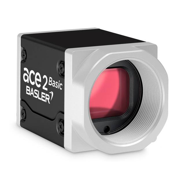
iRAYPLE A9B57CP050E / A9B57MP340E 25MP CXP-12 Large Area Scan Camera
A9B57CP050E
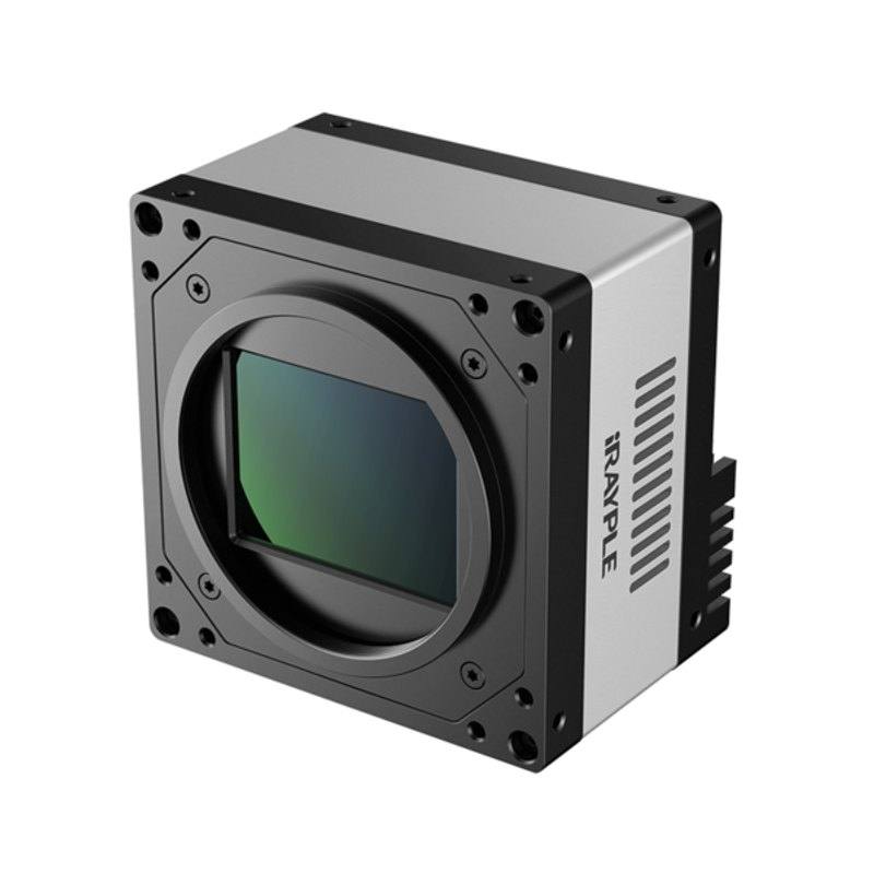
The A9B57CP050E (color) and A9B57MP340E (mono) are high-performance 25MP large area scan cameras based on the 1.1-inch Gpixel GMAX0505 global-shutter CMOS sensor at 5120×5120 pixels with 2.5 µm pixel pitch. Both variants achieve 150 fps and connect via CoaXPress CXP-12 (4×12.5 Gbps) with PoCXP and DC 24V power options. The cameras offer 10-bit output, 63 dB dynamic range, 36 dB SNR, pixel-level flat-field correction, 2 GB onboard image buffer, and GenICam/CoaXPress protocol compliance. Physical format is 80×80 mm with M58×0.75 lens mount (color) or M42×1 (mono), weighing 890 g, and operating from −30 °C to 50 °C.
The A9B57CP050E (color) and A9B57MP340E (mono) are built around the Gpixel GMAX0505, a 1.1-inch global-shutter CMOS sensor that delivers a 5120 × 5120 pixel array — 26,214,400 pixels, marketed by iRAYPLE as 25 MP — with 2.5 µm pixel pitch. The global shutter is the critical design choice here: every pixel integrates simultaneously, so fast-moving parts, conveyor belts, and rotating assemblies are captured without the geometric distortion or motion-induced smear that a rolling shutter would introduce. At 2.5 µm, the pixel is fine enough to resolve very small features at practical working distances, while the 1.1-inch optical format keeps large-format lens choices affordable. A 63 dB dynamic range and 36 dB SNR mean the sensor handles scenes with bright specular highlights alongside dark recessed areas — a common challenge on machined metal or reflective packaging — within a single exposure, without HDR blending overhead. The 10-bit output preserves 1024 grey levels per channel, giving downstream algorithms the tonal depth needed for subtle contrast-based defect detection or accurate grey-value measurement.
The CoaXPress CXP-12 interface uses four coax links each running at 12.5 Gbps, for an aggregate 50 Gbps downstream bandwidth. This is what makes 150 fps at full 5120 × 5120 resolution practically reachable: no other standard machine-vision interface (GigE, USB3 Vision, Camera Link Full) comes close at this pixel count. A single coaxial cable carries both image data and camera control in the upstream direction, while PoCXP delivers power over the same line — significantly simplifying cable routing in multi-camera gantry or line-scan-replacement setups. A fallback 24 V DC input via 12-pin Hirose connector is available when PoCXP is not supported by the frame grabber. The onboard 2 GB image buffer absorbs burst sequences without stalling the sensor pipeline, which matters for step-and-repeat acquisition or trigger bursts during machine indexing cycles. GenICam compliance means integration into standard vision runtime environments requires no custom driver layer; all feature nodes — exposure, gain, flat-field correction, ROI — are accessible through the standard interface.
The physical envelope is 80 × 80 × 72 mm and 890 g — compact relative to the sensor format, though heavier than typical 1-inch cameras due to the heat-dissipating body needed to sustain 19.4 W continuous operation at 150 fps. The color variant uses an M58 × 0.75 lens mount, matching the large 1.1-inch image circle and the wide range of high-resolution M58 lenses designed for large-format sensors; the mono variant uses M42 × 1, opening compatibility with precision metrology and scientific lens families. Resolving 2.5 µm pixels demands lenses rated to at least 200 lp/mm at the sensor plane — budget lenses will soft-limit resolving power before the sensor does. The −30 °C to 50 °C operating range covers most factory floor and outdoor inspection enclosures without active cooling. Pixel-level flat-field correction is onboard, compensating for vignetting and PRNU across the full sensor area so measurement accuracy is not degraded at field edges — essential when the entire 5120 × 5120 frame is used for dimensional gauging rather than presence/absence detection.
Best for
High-throughput wafer and panel inspection in semiconductor and flat-panel display manufacturing, where 150 fps at full 25 MP resolution enables complete surface coverage without tiling or stitching across die-level features.
Large-format surface defect detection on automotive body panels, battery electrode sheets, or rolled materials, where the wide field covers significant physical area per frame and global shutter prevents motion artifacts on moving webs.
Precision dimensional measurement of medium-to-large mechanical assemblies where 2.5 µm pixels and onboard flat-field correction deliver sub-pixel measurement repeatability across the full field without distortion penalties from stitched multi-camera rigs.
Pharmaceutical blister-pack, label, and primary packaging inspection requiring simultaneous colour fidelity (A9B57CP050E) or maximum sensitivity (A9B57MP340E) at line speeds that demand high frame rates to keep up with indexing cycles.
Multi-layer PCB and electronics substrate AOI where the combination of fine pixel pitch, high SNR, and 10-bit depth resolves fine-pitch component placement errors and pad/trace anomalies across a full panel in a single shot.
Selection notes
Frame grabber selection is non-negotiable: CXP-12 at four links requires a host PCIe frame grabber with sufficient PCIe bandwidth; verify the grabber's sustained DMA rate can sustain 150 fps × 25 MP × 10-bit before committing to the system architecture.
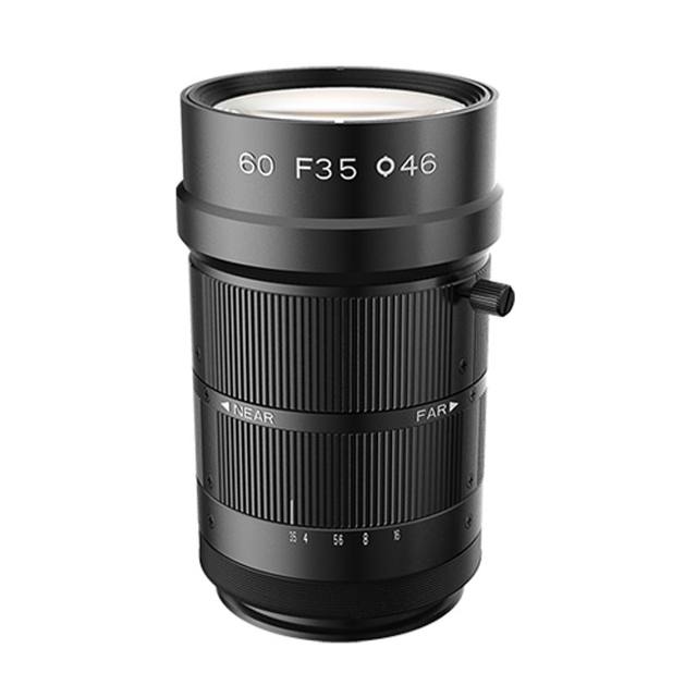
Lens choice must be matched to the 1.1-inch image circle and 2.5 µm pixel pitch — the color variant's M58 × 0.75 mount accepts large-format telecentric or entocentric lenses designed for this format; use lenses specified at ≥ 200 lp/mm resolution at the sensor plane to avoid front-end optical limiting of resolving power.
At 19.4 W continuous dissipation running at full 150 fps, adequate convective or forced-air cooling of the camera body is required; mounting to a large aluminum fixture plate or adding a direct-contact cooler prevents thermal throttling during extended production runs.
The 2 GB onboard buffer is best leveraged in triggered burst modes — configure the camera's buffer management in GenICam to pre-allocate the full buffer for burst depth, particularly in step-and-repeat indexer applications where the host PC may have intermittent DMA latency.
For dimensional metrology applications, enable pixel-level flat-field correction from onboard calibration data before deployment and re-calibrate after any lens change; without FFC, PRNU and vignetting across the 5120 × 5120 field will introduce systematic measurement bias at field edges.
Matched automatically by: lens mount fits the camera mount · lens image circle covers the camera sensor — this camera: M58×0.75 (color) / M42×1 (mono) · 1.1" (diagonal) sensor.
Follow these steps to bring up your iRAYPLE camera, capture a first image, and move from the viewer to your own application. The flow is the same across the A, AE, AX and L series; only the physical interface differs.
Download and install the iRAYPLE machine-vision SDK together with its viewer client for your operating system. The installer provides the camera drivers, the GenTL producer, and the viewer you will use for first light. For GigE Vision models, also install or enable the bundled filter/performance driver on the network adapter to maximize throughput.
2. Connect the camera to the correct interface
Wire the camera to its matching host interface: a dedicated Gigabit (or 10 GigE) NIC for GigE Vision models, a USB3 Vision port with a quality cable for USB3 models, or a frame grabber for CoaXPress models. Power the camera (PoE, USB bus power, or PoCXP / external supply as applicable). For GigE Vision, put the NIC and camera on the same subnet and, where supported, enable jumbo frames.
3. Detect and open the camera in the viewer
Launch the iRAYPLE viewer, run device enumeration, and select your camera from the discovered list. Open it to load the device feature tree (GenICam node map). If a GigE camera is found but cannot be opened, correct the IP configuration so the camera and NIC are in the same address range.
4. Set exposure, gain and trigger, then grab a first image
Start with continuous (free-run) acquisition under stable lighting. Adjust exposure time and gain for a well-exposed, low-noise image, set the pixel format (e.g. Mono8 or a Bayer/RGB format), and tune white balance on color models. Once the live image looks correct, switch trigger mode to hardware or software trigger to synchronize capture with your process, and verify a single triggered frame.
5. Move from the viewer to the SDK or a GenICam library
With imaging confirmed, reproduce the same settings in code using the SDK's C/C++ or Python API: enumerate, open, configure the relevant GenICam features, register a frame callback or grab loop, and convert frames to your pipeline's buffer format. Since the cameras are GenICam/GenTL-compliant, you can alternatively drive them from a third-party GenICam vision library. From here a stable image stream can feed a deep-learning inspection step such as Rosepetal for automated quality control.
Frequently asked questions
The camera uses CoaXPress CXP-12 with four coax links (4 × 12.5 Gbps). You need a CXP-12 quad-link frame grabber with PCIe Gen3 ×8 or ×16 bandwidth. PoCXP support on the grabber eliminates the need for a separate 24 V DC supply, though the 12-pin Hirose DC input is available as a fallback.
Both share the same Gpixel GMAX0505 sensor, 5120 × 5120 resolution, 150 fps, CXP-12 interface, and physical dimensions. The color variant (CP050E) includes a Bayer color filter array and uses an M58 × 0.75 lens mount; the mono variant (MP340E) has no color filter — delivering higher sensitivity and cleaner grey-value data — and uses an M42 × 1 lens mount.
Yes. PoCXP (Power over CoaXPress) is supported, so a compatible CXP-12 frame grabber can deliver power through the coax link. A DC 24 V input via 12-pin Hirose connector is also available for frame grabbers that do not support PoCXP.
The color variant (A9B57CP050E) uses M58 × 0.75; the mono variant (A9B57MP340E) uses M42 × 1. Standard C-mount lenses are not suitable: C-mount covers only an ~11 mm image circle diagonal, which is far smaller than the 1.1-inch (approximately 17.6 mm diagonal) sensor format, causing severe vignetting. Only lenses designed specifically for 1.1-inch or larger image circles should be used.
The pixel-level flat-field correction onboard compensates for per-pixel gain and offset non-uniformity (PRNU and FPN) across the full 5120 × 5120 array, which is the primary source of systematic measurement error from the sensor itself. For highest-accuracy metrology you should additionally perform a geometric distortion calibration using a calibration target in your optics-and-camera combination, since lens distortion is not corrected by the camera's FFC.