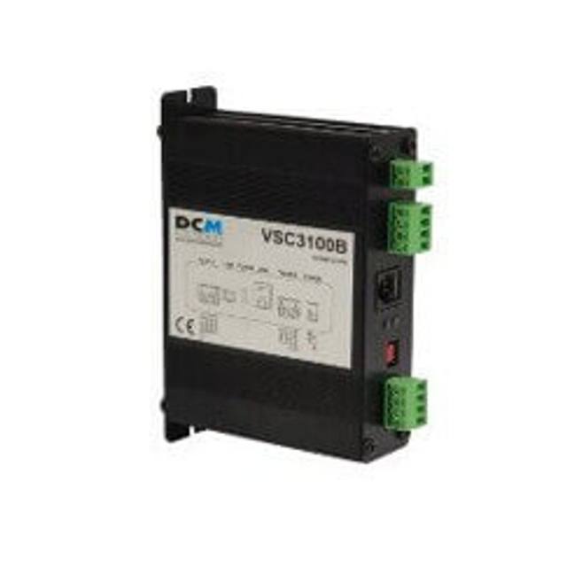
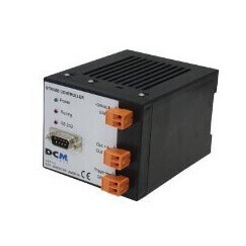
The DCM Sistemes VST11I is a strobe (overdrive) lighting controller with 1 trigger input and 1 output rated at 6A maximum peak current. It is powered from 24VDC and drives lighting at 24V, with a programmable pulse width to set illumination intensity. The trigger input accepts PNP or NPN signals and connections are made via screw terminals. It guarantees strobe working limits (maximum consumption, maximum on-time and recovery time) so fast-moving objects can be frozen even with longer camera shutter times.
Brand
DCM Sistemes
Mode
Strobe (stroboscopic) drive mode
Controller required
This is the controller itself (drives external strobe lighting)
The DCM Sistemes VST11I is a single-channel strobe (overdrive) controller whose job is to drive an external DCM Sistemes LED light in stroboscopic mode rather than to produce any image features itself. It runs from a 24VDC supply and outputs to the lighting at 24V, with one trigger input and one output channel rated for a 6A maximum peak current. The defining feature is the programmable pulse width: instead of running a light continuously at its rated level, the controller fires a short, precisely timed burst synchronized to the camera, and the width of that pulse sets the effective illumination intensity. Because the LED is pulsed rather than held on, it can be pushed above its continuous rating during the brief on-time, delivering a much brighter flash than the same light could sustain in continuous operation.
The reason an installer reaches for a strobe controller like this is motion. The VST11I guarantees strobe working limits, meaning it enforces a maximum consumption, a maximum on-time and a recovery time so the LED is protected while still being overdriven. That intense, short flash freezes fast-moving parts on a conveyor or indexing line even when the camera's electronic shutter is comparatively long, because the part is only lit for the duration of the pulse. The trade-off is duty cycle: the higher the peak and the longer the on-time, the longer the controller must wait before it can fire again, which the device manages within its rated working limits.
Integration is deliberately simple. The trigger input accepts both PNP and NPN signals, so it can be driven from a PLC output, a photoelectric sensor or a vision system's strobe line, and all wiring is landed on screw terminals (a terminal block) rather than a proprietary connector. In a typical layout the part-present sensor or the camera's flash output triggers the VST11I, the controller fires the LED for the programmed pulse width, and the camera exposure is timed to coincide with that flash. The controller is the bridge between the trigger source and a compatible DCM Sistemes strobe-capable light; it does not replace the camera, lens or the light itself, all of which must be selected and aligned separately.
Best for
Freezing fast-moving product on packaging conveyors so labels, lids and fill levels can be imaged sharply without motion blur at line speed
Surface inspection of automotive parts on indexing lines where a bright, short flash is needed to reveal scratches, dents or coating defects
Reading 1D/2D traceability codes printed or marked on parts in motion, where a synchronized strobe sharpens the code for reliable decoding
OCR/OCV of printed text such as date or lot codes on moving primary packaging in food and beverage production
Driving an overdriven LED light in electronics assembly inspection where high peak brightness is required for very short exposures
Selection notes
Confirm the LED light you intend to drive is a DCM Sistemes strobe-capable model and that its current draw stays within the controller's 6A peak output at the 24V drive level; this controller is built to pair with DCM Sistemes lights
Budget your duty cycle: the guaranteed strobe working limits set a maximum consumption, a maximum on-time and a recovery time, so verify your line's trigger rate and pulse width leave enough recovery between flashes at full speed
Wire the trigger from your PLC, part-present sensor or camera flash output into the single trigger input; both PNP and NPN sources are accepted, and connections land on screw terminals, so plan terminal access and cable strain relief in the cabinet
Set illumination intensity through the programmable pulse width and time the camera exposure to fully overlap the flash, otherwise the part will be only partially lit; treat the controller, camera trigger and exposure as one synchronized timing chain
Provide a 24VDC supply capable of the peak current the strobe draws, and remember this single-channel unit drives one output only; if you need to fire multiple lights or independent channels you will need additional controllers or a multi-channel alternative
Specifications: General
Brand
DCM Sistemes
Specifications: Interface
Connection
Terminal block
Specifications: Electrical
Mode
Strobe (stroboscopic) drive mode
Controller required
This is the controller itself (drives external strobe lighting)
Supply voltage
24 VDC
Applications this camera is commonly selected for. Open one to see the full recommended hardware and approach.
It is the controller. The VST11I is the strobe (overdrive) lighting controller itself, and its purpose is to drive an external DCM Sistemes stroboscopic light. You do not add another controller in front of it.
It has a single output rated for a maximum peak current of 6A, driving the lighting at 24V. The light you connect must stay within that 6A peak limit.
Yes. The single trigger input accepts both PNP and NPN signals, so it can be driven from a PLC output, a photoelectric sensor or a vision system's strobe output.
Intensity is set by the programmable pulse width. A longer pulse delivers more light, within the controller's guaranteed strobe working limits for maximum consumption, on-time and recovery time.
Strobe overdrive fires a short, intense flash synchronized to the camera, which freezes fast-moving objects even with longer camera shutter times, and lets the LED be pushed brighter than it could be run continuously.
It is powered from 24VDC and all connections, including the trigger input and the output to the light, are made on screw terminals (a terminal block).