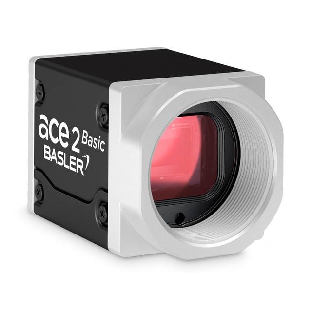
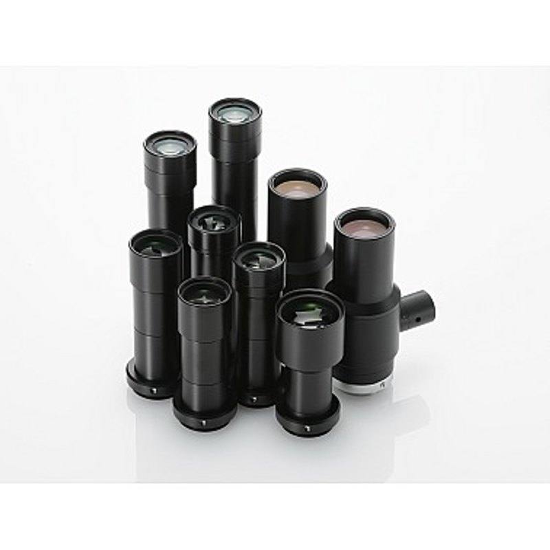
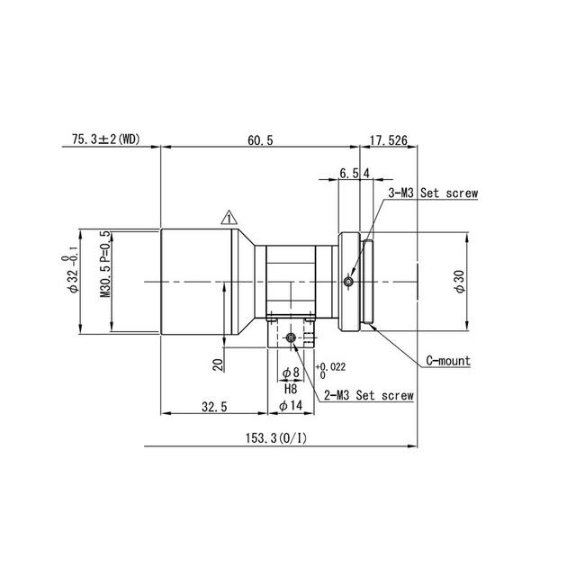
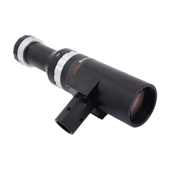
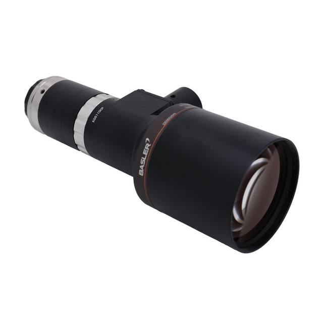
The VS-TCH1.5-65CO-O is a 1.5x optical magnification, object-space telecentric lens designed for C-mount industrial machine vision cameras up to 2/3" sensor format. It features an effective F-number of F11.8, a 65 mm working distance, 0.4 mm depth of field, and 5.24 µm optical resolution at 550 nm. The coaxial (-CO) configuration integrates a built-in coaxial illumination port for shadowless, glare-free illumination of reflective or specular surfaces. TV distortion is rated at 0.01%, making it ideal for high-precision dimensional measurement and alignment tasks.
The VS-TCH1.5-65CO-O is a 1.5x magnification, object-space telecentric lens mounted on a standard C-mount, covering sensors up to 2/3" in format. Object-space telecentricity means that the chief rays entering the lens are parallel to the optical axis across the entire field, so the apparent size of a feature does not change with its height above or below the focal plane. With a 0.4 mm depth of field and a fixed 65 mm working distance, this is a lens designed to eliminate perspective error entirely for precision gauging tasks — a part standing 0.1 mm proud of its nominal height will produce no measurable width error in the image, which is the fundamental requirement for sub-pixel dimensional metrology.
The optical performance figures are tightly specified. The effective aperture is F11.8 and the TV distortion is rated at 0.01%, which is an order of magnitude better than most standard C-mount lenses and sufficient to support traceable dimensional measurement without software distortion correction. Optical resolution reaches 5.24 µm at 550 nm, meaning the lens can resolve feature edges finer than typical pixel pitch on 2/3" megapixel sensors — so the lens is not the limiting factor in resolution when paired with an appropriate camera. The 74 g weight is modest and the C-mount interface is compatible with the full range of industrial cameras offered in the 2/3" format.
The -CO suffix identifies the coaxial illumination port, which is the distinguishing design element that separates this variant from the standard telecentric model. The coaxial port injects light along the optical axis so that it returns specularly from flat, polished, or mirror-like surfaces — solder pads, bare metal, polished ceramics, glass wafer edges — and is collected by the lens rather than scattered away. For a reflective surface without coaxial illumination, bright-field diffuse lighting typically produces glare hot-spots that obscure edge detail; the coaxial port eliminates that problem cleanly. The coaxial port is built into the lens barrel, so the illumination geometry is fixed and repeatable, which simplifies setup and qualification compared to an external beamsplitter arrangement.
Best for
Sub-pixel dimensional gauging of machined or stamped metal parts, where the 0.01% TV distortion and telecentric projection allow caliper-grade width and diameter measurements directly from camera pixels without per-unit calibration of perspective correction.
PCB and semiconductor solder-joint or bond-pad inspection on reflective surfaces, where the integrated coaxial illumination port provides shadowless axial lighting that makes pad edges and solder fillets clearly visible without glare artifacts.
Pharmaceutical tablet and medical-device dimensional conformance checks, where regulatory traceability requires a demonstrably low-distortion optical chain and part height variation must not introduce sizing errors in the image.
Glass, ceramic, or polished-surface defect inspection (chips, cracks, scratches) on flat or near-flat substrates, where specular coaxial lighting reveals surface-normal discontinuities as dark features against a bright field.
Precision alignment and registration tasks in electronics assembly — verifying component placement relative to pad centers or fiducials — where telecentric imaging ensures that a component sitting at a slightly different height than the reference fiducial does not appear shifted laterally in the image.
Selection notes
Sensor format compatibility: the lens covers up to 2/3" sensors. Pairing it with a camera that has a larger sensor format will result in severe vignetting at the image corners. For 1/2" or 1/1.8" cameras the image circle is overfilled and the full telecentric field is preserved, but effective field of view narrows proportionally.
Fixed working distance: the working distance is 65 mm with no focusing adjustment, which is standard for telecentric designs to maintain the telecentric condition. The entire optical system — part, fixture, and camera mount — must be engineered to this exact standoff before integration begins. Verify that the part height envelope fits within the 0.4 mm depth of field, or tolerance stack analysis will be needed.
Coaxial illumination source: the -CO port requires a separate coaxial light controller or fiber illuminator matched to the port geometry. The lens itself does not include a light source. Verify beam diameter, fiber bundle size, and intensity uniformity requirements with the illumination vendor before ordering.
Magnification and field of view: at 1.5x magnification the image is larger than the object, so the physical field of view on a 2/3" sensor (8.8 mm x 6.6 mm sensor area) is approximately 5.9 mm x 4.4 mm. Confirm that the largest expected part fits within this field before selecting the lens — if a wider field is needed, a lower magnification telecentric model will be necessary.
Aperture and lighting power: the F11.8 effective aperture is relatively small, which reduces the amount of light reaching the sensor. In strobe mode this can be compensated with high-peak-current LED drivers, but continuous illumination setups should verify that the camera can achieve acceptable SNR at the required exposure time without pixel saturation from the coaxial source.
Specifications: General
Brand
Omron / Sentech
Specifications: Optical
Lens mount
C-mount
Telecentric
Yes
Magnification
1.5x
Working distance
65 mm
Aperture (f-number)
F11.8
Image circle / max sensor
2/3" (max compatible sensor)
Specifications: Mechanical
Weight
74 g
Applications this camera is commonly selected for. Open one to see the full recommended hardware and approach.
Matched automatically by: camera mount fits the lens mount · camera sensor is covered by the lens image circle — this lens: C-mount · 2/3" (max compatible sensor) image circle.
By category
All 758Area scan cameras 622High-speed cameras 108High-resolution cameras 28
By brand
All 758Omron / Sentech 297Basler 242iRAYPLE 200Datalogic / Datasensing 19
These steps take an Omron Sentech (STC) camera from the box to a stable first image and on to your own application. They apply across the GigE Vision, USB3 Vision and CoaXPress STC families; the interface only changes how you cable and power the camera.
Download and install the Sentech SDK on the host PC. The package provides StViewer, the viewing and configuration software you use to bring the camera up, and StApi, the programming SDK you integrate later. Because the cameras are GenICam/GenTL-compliant, StApi also registers a GenTL producer, so any GenICam-compliant third-party vision software can discover and drive the camera as an alternative front end.
2. Cable, power and connect the camera
Connect according to the interface. GigE Vision: link to a Gigabit NIC (use PoE or the separate power input) and put the camera and host on the same subnet; for USB3 Vision use a USB 3.x port and a certified cable; for CoaXPress (STC) connect to a CoaXPress frame grabber, which also supplies Power-over-Coax. Then open StViewer and let it enumerate the camera. If a GigE camera does not appear, check the IP configuration and firewall, and on USB3 confirm the host bandwidth and driver.
3. Configure exposure, gain and white balance
Open the device in StViewer and start a live stream. Set exposure and gain for a well-exposed, low-noise image: raise exposure first and only add gain when more light or a faster shutter is not an option, keeping exposure short enough to freeze motion on global-shutter models. On colour cameras, run white balance under your actual production lighting. Adjust the lens aperture and focus on a representative target before tuning anything else.
4. Set the trigger and grab a first image
Start in free-run (continuous) acquisition to confirm a clean, stable image. For inline inspection switch to hardware or software triggering: select the trigger source, set the active edge and any delay, and wire the strobe or illumination to the camera's I/O so lighting fires with each exposure. Acquire and save a frame in StViewer; this saved image is your reference for the SDK stage and for downstream inspection.
5. Move to the StApi SDK (or any GenICam software)
Once the image is stable, reproduce the same settings in code. Use StApi to open the device, apply the GenICam features you validated in StViewer (exposure, gain, trigger, pixel format) and grab frames into your application via the bundled C++, C, C#/.NET or Python interfaces; the included samples are the fastest starting point. Prefer a different stack? The same GenICam/GenTL camera works with third-party vision libraries. With a reliable feed, you can route it into a deep-learning inspection such as Rosepetal for AI-based defect detection.
Frequently asked questions
The lens is specified for a maximum image circle corresponding to 2/3" sensor format. Cameras with sensors larger than 2/3" will experience vignetting toward the image corners. The lens performs correctly with any sensor up to and including 2/3".
No. Telecentric lenses are designed around a fixed working distance — in this case 65 mm — to preserve the telecentric condition. Changing the standoff distance breaks telecentricity and reintroduces perspective error. Part height variation is tolerated only within the 0.4 mm depth of field around the nominal 65 mm plane.
The coaxial illumination port is built into the lens barrel but does not include a light source. A separate coaxial illuminator or fiber-coupled light source matched to the port must be sourced independently. Verify the port geometry and fiber bundle diameter with the illumination supplier.
TV distortion is rated at 0.01%. For most dimensional metrology applications this is negligible and no distortion calibration step is needed. Standard machine vision lenses typically run 0.1–1%, so this lens provides a meaningfully lower error budget without software correction overhead.
Optical resolution is specified at 5.24 µm at 550 nm wavelength. Most 2/3" megapixel cameras have pixel pitches in the 3–5 µm range; at 1.5x magnification the effective pixel size at the object plane is 2–3 µm, so a well-matched camera with ~4–5 µm pixels will see the lens and sensor resolving at similar spatial frequencies. The lens is not the performance bottleneck for typical 2–5 MP 2/3" sensors.