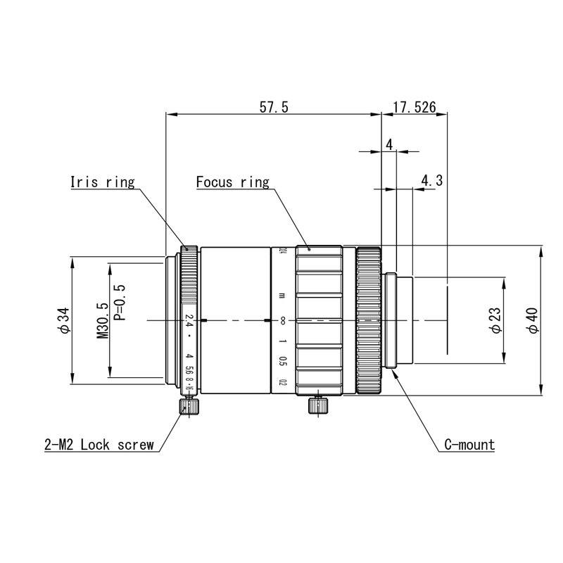
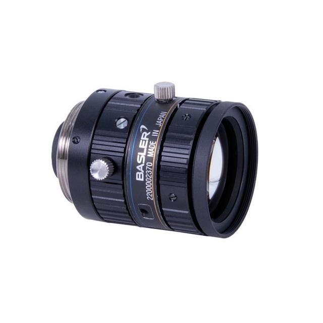
The VS-HVA5024 is a 50 mm fixed focal length C-mount lens designed for ultra-high-resolution industrial imaging, supporting up to 1.1" sensor formats with a 2.74 μm pixel pitch and 20 MP rating. It offers a maximum aperture of F2.4 with manual iris control and covers a field of view of 12.0° × 16.4° (diagonal 20.3°) on a 1.1" sensor. TV distortion is minimized to just 0.03% on the 1.1" format, making it suitable for high-precision dimensional measurement and inspection. The compact body (Ø40 × 57.5 mm, 142 g) uses a C-mount interface with a flange back distance of 17.526 mm and accepts M30.5 P=0.5 filters.
The VS-HVA5024 is a 50 mm fixed focal length C-mount lens purpose-built for the highest-density sensors in current production use. Its 17.6 mm image circle covers the full 1.1" sensor format, which today encompasses 20 MP large-format CMOS chips with pixel pitches down to 2.74 µm. A lens matched to that pitch must resolve detail at the Nyquist limit of the sensor — roughly 182 lp/mm — and Omron rates this optic at 20 MP to confirm it can sustain that MTF across the entire field rather than just at the center. The F2.4 maximum aperture gives meaningful light-gathering headroom for short exposure times without forcing an excessively narrow depth of field, and manual iris control lets integrators lock the aperture once the working-distance and depth-of-field budget are confirmed, eliminating any possibility of automatic aperture drift between frames.
On a 1.1" sensor the lens produces a field of view of 12.0° × 16.4° (20.3° diagonal). At the 200 mm minimum working distance this translates to a narrow, telephoto-like field well suited to close-range inspection of small components or fine print where you need both high magnification and tight angular perspective. Critically, TV distortion on the 1.1" format is held to just 0.03% — a figure that competes with metrology-grade optics. At that distortion level a 20 MP image can be used for dimensional measurement without software correction; the geometric error at the edge of a 17.6 mm image circle from 0.03% distortion is less than 3 µm, which is within the pixel pitch of the sensor itself. The 17.526 mm C-mount flange-back distance is standard, so the lens drops directly onto any C-mount camera body without a shim or adapter. The M30.5 P=0.5 front filter thread accommodates standard industrial bandpass, polarizing, or neutral-density filters.
The physical envelope — 40 mm maximum diameter and 57.5 mm body length at 142 g — fits inside standard C-mount camera housings and leaves room on compact inspection heads. The form factor is relevant because 20 MP cameras paired with 1.1" sensors often run on high-bandwidth interfaces where the camera body is already relatively large; a lens that does not overhang the camera width avoids bracket conflicts on tight multi-camera gantries. Because the lens is not telecentric, parallax error will appear when measuring part features at different heights from the focal plane, so applications requiring true 3D-independent measurement should note that constraint and either fix the part height tightly or add a telecentric alternative for the highest-accuracy axes.
Best for
High-resolution surface and defect inspection on 20 MP 1.1" sensors, where the 0.03% TV distortion and 20 MP optical rating mean every pixel contributes clean, undistorted detail across the full sensor area.
Precision dimensional measurement of small components — PCBs, semiconductor packages, connector housings — at working distances from 200 mm, where the 50 mm focal length delivers a telephoto perspective that reduces perspective-induced measurement error on flat parts.
Industrial OCR and code reading on fine-pitch marks (laser-etched 2D codes, dot-peen traceability marks) where resolving individual dot cells at 2.74 µm per pixel demands a lens that does not soft-clip the sensor's native resolution.
Multi-sector inline inspection lines in electronics, automotive, pharmaceutical, and food packaging where one standardized C-mount optic covers a broad range of 1.1" camera upgrades without changing the physical mounting envelope.
Applications that require optical bandpass or polarization filtering — the M30.5 P=0.5 filter thread accepts standard industrial filter sizes without adapter rings, supporting glare suppression on specular surfaces or wavelength isolation for color-based defect detection.
Selection notes
Sensor format compatibility is the first design-in check: the 17.6 mm image circle covers 1.1" sensors fully and smaller formats (1", 2/3", 1/2") without vignetting, but it will not cover sensors larger than 1.1". Confirm your camera's sensor format before specifying this lens.
The 200 mm minimum working distance is a hard constraint set by the lens's closest-focus design. Inspection stations where the part-to-lens distance is shorter than 200 mm will require either a different focal length or the addition of a close-up lens element, both of which affect the distortion and MTF specs.
Because this is a non-telecentric lens, height variation in the part under inspection introduces magnification change. For dimensional measurements requiring better than ±0.1% accuracy, restrict the acceptable height variation of the part or use a telecentric lens on the critical measurement axis.
Manual iris control is correct for fixed-line installations where ambient light is controlled, but integrators must lock the iris ring mechanically (or confirm the detent is firm) after commissioning — any aperture creep from vibration will shift depth of field and image brightness between frames.
The front thread is M30.5 P=0.5; verify filter availability in your preferred bandpass wavelength before finalizing the BOM, particularly for narrow-band NIR or UV filters used in pharmaceutical or semiconductor inspection.
Specifications: General
Brand
Omron / Sentech
Specifications: Optical
Focal length
50 mm
Lens mount
C-Mount
Aperture (f-number)
F2.4 ~ Close
Image circle / max sensor
17.6 mm (1.1")
Optical resolution
20 MP
Telecentric
No
Working distance
200 mm (min)
Specifications: Mechanical
Dimensions
Ø40 (max) × L=57.5 mm
Weight
142 g
Applications this camera is commonly selected for. Open one to see the full recommended hardware and approach.
Matched automatically by: camera mount fits the lens mount · camera sensor is covered by the lens image circle — this lens: C-Mount · 17.6 mm (1.1") image circle.
These steps take an Omron Sentech (STC) camera from the box to a stable first image and on to your own application. They apply across the GigE Vision, USB3 Vision and CoaXPress STC families; the interface only changes how you cable and power the camera.
Download and install the Sentech SDK on the host PC. The package provides StViewer, the viewing and configuration software you use to bring the camera up, and StApi, the programming SDK you integrate later. Because the cameras are GenICam/GenTL-compliant, StApi also registers a GenTL producer, so any GenICam-compliant third-party vision software can discover and drive the camera as an alternative front end.
2. Cable, power and connect the camera
Connect according to the interface. GigE Vision: link to a Gigabit NIC (use PoE or the separate power input) and put the camera and host on the same subnet; for USB3 Vision use a USB 3.x port and a certified cable; for CoaXPress (STC) connect to a CoaXPress frame grabber, which also supplies Power-over-Coax. Then open StViewer and let it enumerate the camera. If a GigE camera does not appear, check the IP configuration and firewall, and on USB3 confirm the host bandwidth and driver.
3. Configure exposure, gain and white balance
Open the device in StViewer and start a live stream. Set exposure and gain for a well-exposed, low-noise image: raise exposure first and only add gain when more light or a faster shutter is not an option, keeping exposure short enough to freeze motion on global-shutter models. On colour cameras, run white balance under your actual production lighting. Adjust the lens aperture and focus on a representative target before tuning anything else.
4. Set the trigger and grab a first image
Start in free-run (continuous) acquisition to confirm a clean, stable image. For inline inspection switch to hardware or software triggering: select the trigger source, set the active edge and any delay, and wire the strobe or illumination to the camera's I/O so lighting fires with each exposure. Acquire and save a frame in StViewer; this saved image is your reference for the SDK stage and for downstream inspection.
5. Move to the StApi SDK (or any GenICam software)
Once the image is stable, reproduce the same settings in code. Use StApi to open the device, apply the GenICam features you validated in StViewer (exposure, gain, trigger, pixel format) and grab frames into your application via the bundled C++, C, C#/.NET or Python interfaces; the included samples are the fastest starting point. Prefer a different stack? The same GenICam/GenTL camera works with third-party vision libraries. With a reliable feed, you can route it into a deep-learning inspection such as Rosepetal for AI-based defect detection.
Frequently asked questions
The lens has a 17.6 mm image circle, which fully covers 1.1" format sensors (the largest common format for 20 MP CMOS chips) as well as all smaller formats down to 1/2". It is not designed for sensors larger than 1.1" and will vignette on those.
On a 1.1" sensor the lens produces 12.0° × 16.4° (20.3° diagonal). At 200 mm working distance these angles correspond to a horizontal span of approximately 42 mm and a vertical span of approximately 58 mm, giving a rough idea of the inspection window at closest focus.
For most industrial dimensional-measurement tasks, yes. At 0.03% distortion on a 17.6 mm image circle, the maximum geometric error at the edge of the field is well under 3 µm — within one pixel at 2.74 µm pitch. Raw-image measurements can therefore be used directly without a polynomial distortion-correction step, which simplifies the metrology pipeline and removes a calibration variable.
The front thread is M30.5 with a 0.5 mm pitch. Verify filter availability with your supplier — especially for narrow-band or custom coatings — before finalizing the design.
No adapter is required. The lens is specified with the standard C-mount flange-back distance of 17.526 mm and mounts directly on any C-mount camera body. No shims or spacers are needed for standard cameras; verify only if using a camera with a non-standard back-focal adjustment.