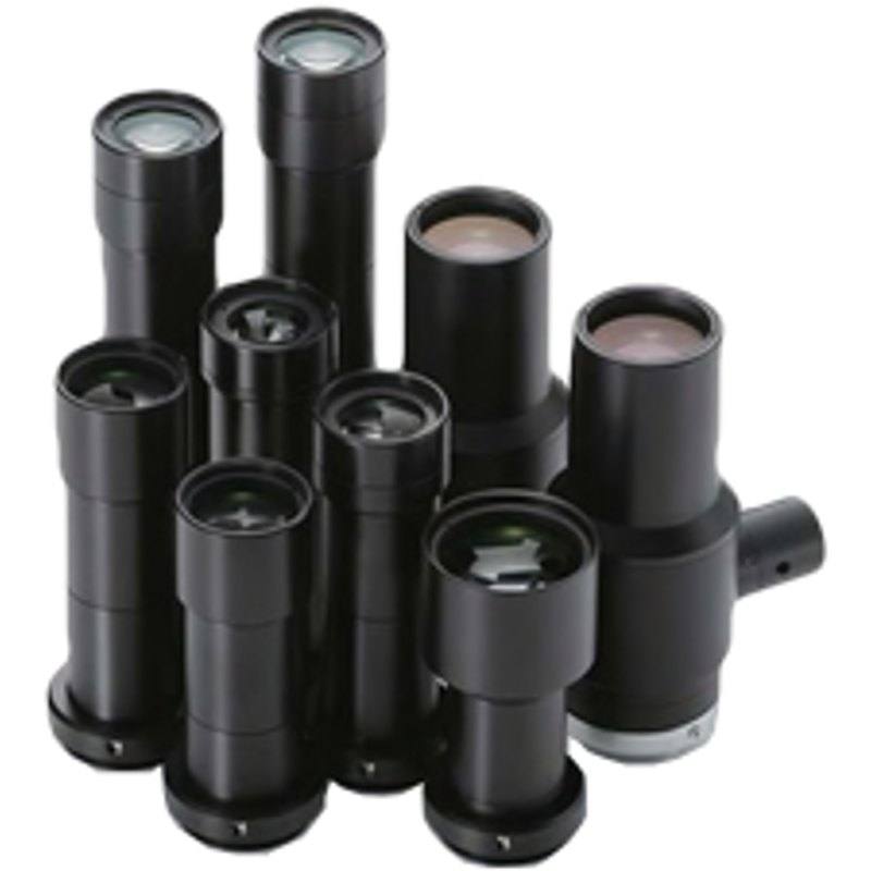
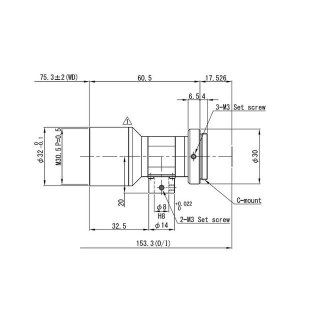
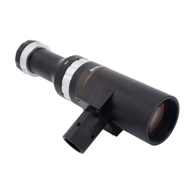
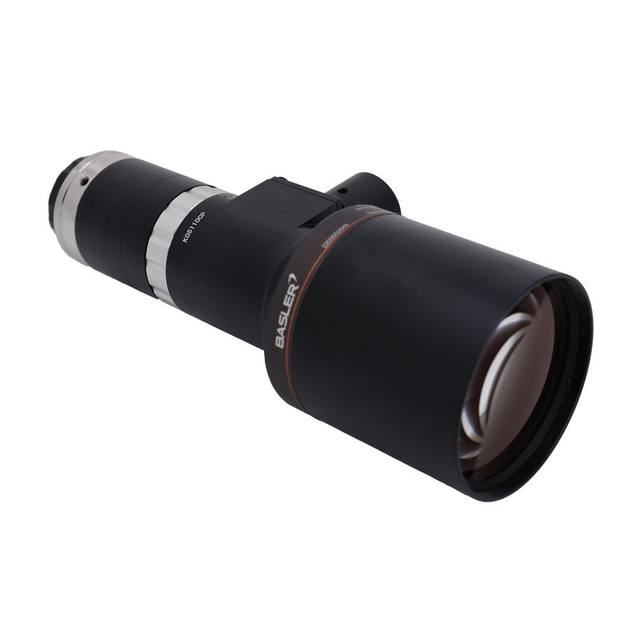
The VS-TCH4-65CO-O is a 4.0x magnification telecentric lens designed for C-mount megapixel cameras, covering up to 2/3" sensors with an FOV of 1.7×2.2 mm on that format. It delivers an effective f-number of f/17.91, NA of 0.112, and 3.0 µm optical resolution at 550 nm, with a best-in-class TV distortion of just 0.02% for accurate dimensional measurement. A built-in coaxial prism enables direct coaxial illumination without an external adapter, and the lens operates across the visible spectrum (400–700 nm). Physical dimensions are Φ30 mm × 105.3 mm with a weight of 94.5 g.
The VS-TCH4-65CO-O is a 4.0x magnification fixed-magnification telecentric lens, meaning its chief rays travel parallel to the optical axis on the object side. This telecentricity eliminates perspective error: a feature that shifts laterally within the ±2 mm depth-of-field zone around the 65 mm working distance produces no apparent change in its projected size on the sensor. At 4.0x on a 2/3" (11 mm diagonal) sensor, the imaged field of view is approximately 1.7 × 2.2 mm — a very small FOV suited to high-magnification inspection of sub-millimetre features such as bond pads, via holes, micro-stamped characters, or pharmaceutical tablet markings. The lens is rated for 2 MP sensors (2/3" format), so at 1.7 × 2.2 mm field the achievable pixel pitch on the object is on the order of approximately 1.4 µm/pixel for a typical 1600 × 1200 sensor, consistent with the 3.0 µm optical resolution at 550 nm.
The optical performance specification most relevant to dimensional gauging is TV distortion of 0.02% maximum. Across the short axis of the 1.7 mm field, 0.02% corresponds to a positional error of roughly 0.34 µm — well below the 3.0 µm optical resolution limit and well below typical sub-pixel interpolation targets. This makes the lens a legitimate choice for metrological applications where edge-detection accuracy directly translates to a tolerance call. The effective aperture of f/17.91 (NA 0.112 on the object side) is a fundamental trade-off inherent to high-magnification telecentrics: depth of field is extended relative to a fast lens, but illumination throughput is low, requiring a bright, stable light source. The built-in coaxial prism is the key integration feature — it couples a coaxial light source directly into the optical path without an external beam-splitter adapter, eliminating an alignment variable and keeping the assembly compact at Ø30 mm × 105.3 mm / 94.5 g.
For system builders, the C-mount interface is the correct starting point for camera selection. At 4.0x magnification, only cameras with sensor diagonals at or below 11 mm (2/3") are fully covered; a larger sensor will vignette or fall outside the corrected image circle. The visible-spectrum design range (400–700 nm) means standard broadband LED coaxial illuminators in white or green (550 nm, where the 3.0 µm resolution is specified) are the natural pairing. Because the lens has no focus-adjustment travel — working distance is fixed at 65 ± 2 mm — the camera-to-part stand-off must be controlled mechanically by the integrator. Fine Z-positioning is typically achieved with a motorised stage or a micrometer-driven lens mount on the camera side. Combining the built-in prism with a pulsed LED coaxial driver (strobe mode) allows short exposure times to freeze vibration without sacrificing illumination brightness, which is especially relevant given the modest NA.
Best for
Precision dimensional gauging of micro-components — bond wire geometry, IC package leads, stamped metal contacts, or connector pins — where the 0.02% TV distortion and telecentricity together support sub-pixel edge detection without parallax-induced size error.
High-magnification surface and defect inspection of small flat parts (ceramic components, pharmaceutical tablets, SMD devices) where the 1.7 × 2.2 mm FOV at 4.0x resolves fine surface texture and the coaxial prism delivers shadow-free, specular-contrast illumination in a single compact unit.
Micro-character OCR and DPM code reading on small part surfaces — the 3.0 µm optical resolution and tight distortion budget allow reliable segmentation of dot-peen or laser-marked characters at the millimetre scale.
Semiconductor and PCB quality control stations requiring metrological repeatability across many parts, where a fixed-working-distance optical design eliminates focus drift and the 2 MP rating supports dense feature discrimination at throughput-capable shutter speeds.
Medical device and pharma line inspection of small labelled or moulded components where the visible-spectrum (400–700 nm) coaxial illumination highlights print contrast and surface anomalies.
Selection notes
Working distance is fixed at 65 mm (±2 mm). Unlike a zoom or variable-WD telecentric, there is no focus ring — your mechanical fixture must position the part precisely at 65 mm from the front of the lens. Build in Z-axis adjustability (micrometer stage or motorised axis) during setup and lock it for production.
The maximum sensor size is 2/3" (11 mm diagonal). Pairing with a larger sensor will place the outer pixels outside the corrected image circle, introducing vignetting and resolution falloff at the frame edges. Confirm your camera's sensor format before ordering.
The built-in coaxial prism requires a coaxial illuminator with an appropriately sized input port; verify that your intended LED coaxial light source is physically compatible with the Ø30 mm lens body and the prism's input geometry. External diffuse-dome or ring lights cannot be coupled through the prism and would require a separate working-distance clearance.
At f/17.91 effective aperture the lens transmits relatively little light. For sub-millisecond exposure times needed to freeze vibration or enable high throughput, a high-radiance LED source in strobe mode is typically required. Factor illumination power and duty-cycle limits into your cycle-time budget early.
Magnification tolerance is ±5%, meaning the actual scale factor may range from 3.8x to 4.2x. For metrological applications, calibrate the pixel-to-object scale in situ using a traceable reference target rather than relying on the nominal 4.0x figure.
Specifications: General
Brand
Omron / Sentech
Specifications: Optical
Lens mount
C-mount
Telecentric
Yes
Magnification
4.0x (±5%)
Working distance
65 mm (±2 mm)
Aperture (f-number)
f/17.91 (effective)
Image circle / max sensor
2/3" (11 mm diagonal, max sensor size)
Optical resolution
2 MP rated
Specifications: Mechanical
Weight
94.5 g
Applications this camera is commonly selected for. Open one to see the full recommended hardware and approach.
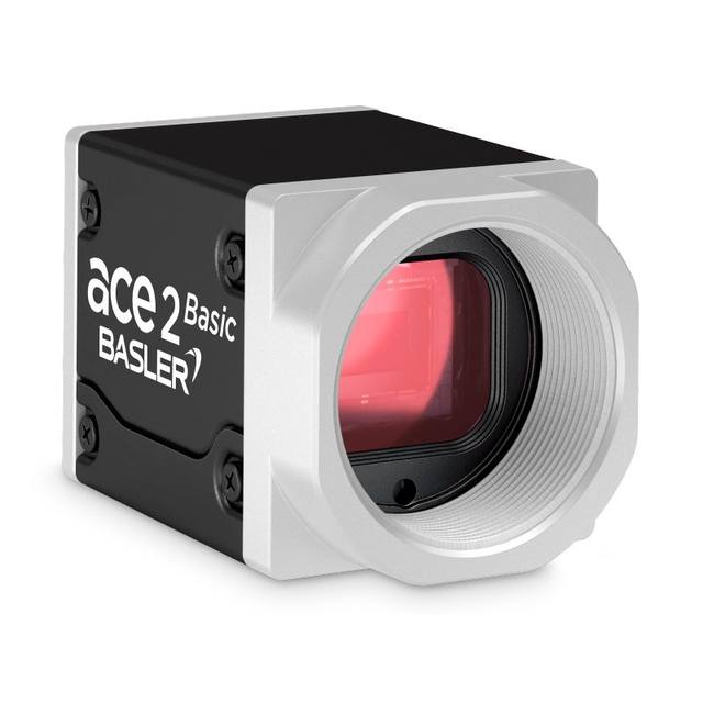
Matched automatically by: camera mount fits the lens mount · camera sensor is covered by the lens image circle — this lens: C-mount · 2/3" (11 mm diagonal, max sensor size) image circle.
By category
All 758Area scan cameras 622High-speed cameras 108High-resolution cameras 28
By brand
All 758Omron / Sentech 297Basler 242iRAYPLE 200Datalogic / Datasensing 19
These steps take an Omron Sentech (STC) camera from the box to a stable first image and on to your own application. They apply across the GigE Vision, USB3 Vision and CoaXPress STC families; the interface only changes how you cable and power the camera.
Download and install the Sentech SDK on the host PC. The package provides StViewer, the viewing and configuration software you use to bring the camera up, and StApi, the programming SDK you integrate later. Because the cameras are GenICam/GenTL-compliant, StApi also registers a GenTL producer, so any GenICam-compliant third-party vision software can discover and drive the camera as an alternative front end.
2. Cable, power and connect the camera
Connect according to the interface. GigE Vision: link to a Gigabit NIC (use PoE or the separate power input) and put the camera and host on the same subnet; for USB3 Vision use a USB 3.x port and a certified cable; for CoaXPress (STC) connect to a CoaXPress frame grabber, which also supplies Power-over-Coax. Then open StViewer and let it enumerate the camera. If a GigE camera does not appear, check the IP configuration and firewall, and on USB3 confirm the host bandwidth and driver.
3. Configure exposure, gain and white balance
Open the device in StViewer and start a live stream. Set exposure and gain for a well-exposed, low-noise image: raise exposure first and only add gain when more light or a faster shutter is not an option, keeping exposure short enough to freeze motion on global-shutter models. On colour cameras, run white balance under your actual production lighting. Adjust the lens aperture and focus on a representative target before tuning anything else.
4. Set the trigger and grab a first image
Start in free-run (continuous) acquisition to confirm a clean, stable image. For inline inspection switch to hardware or software triggering: select the trigger source, set the active edge and any delay, and wire the strobe or illumination to the camera's I/O so lighting fires with each exposure. Acquire and save a frame in StViewer; this saved image is your reference for the SDK stage and for downstream inspection.
5. Move to the StApi SDK (or any GenICam software)
Once the image is stable, reproduce the same settings in code. Use StApi to open the device, apply the GenICam features you validated in StViewer (exposure, gain, trigger, pixel format) and grab frames into your application via the bundled C++, C, C#/.NET or Python interfaces; the included samples are the fastest starting point. Prefer a different stack? The same GenICam/GenTL camera works with third-party vision libraries. With a reliable feed, you can route it into a deep-learning inspection such as Rosepetal for AI-based defect detection.
Frequently asked questions
The specified FOV is 1.7 × 2.2 mm on a 2/3" sensor. This is the maximum FOV the lens is designed and corrected for; smaller sensors (1/2", 1/1.8") will yield proportionally smaller fields.
No. The specified maximum image circle is 11 mm diagonal, which corresponds to the 2/3" format. Sensors with a larger diagonal will record image content outside the corrected circle, resulting in visible vignetting and degraded resolution toward the frame corners. Select a camera at 2/3" or smaller.
Yes — the prism is integrated into the lens body and directs a coaxial beam along the optical axis without requiring a separate beam-splitter cube or adapter ring. You need a coaxial LED light source compatible with the Ø30 mm lens body's prism input port. Consult Omron's illumination accessories that match this lens family, as third-party coaxial lights must be verified for mechanical and optical compatibility.
The lens uses a standard C-mount interface. Confirm that your camera body has a C-mount (not CS-mount) register distance, as the lens is designed for the C-mount flange-focal distance.
The specification states a maximum TV distortion of 0.02%. This is the worst-case figure across the image field. For the 1.7 mm short-axis field, 0.02% corresponds to a maximum positional error of approximately 0.34 µm due to distortion alone — well below the 3.0 µm optical resolution at 550 nm and well below typical sub-pixel localisation uncertainty, so distortion is not the dominant error source in a well-calibrated system.