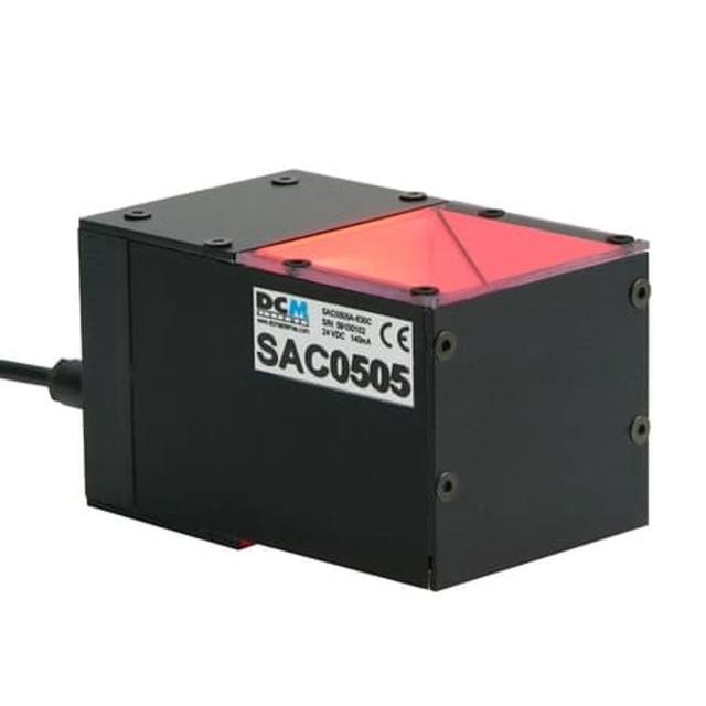
Omron / Sentech FLV-FX143 Edge Type Coaxial Light (143x143mm)
FLV-FX143
The FLV-FX143 is part of Omron's FLV Series and uses edge-lit coaxial optics with a PMMA diffuser and aluminum housing to deliver highly uniform, shadowless illumination over a 143x143mm area. It achieves both shadowless and coaxial illumination simultaneously, making it suitable for flat surface inspection where reflections must be controlled. The unit requires a dedicated Omron FLV lighting controller (FLV-TCC4/TCC1/TCC3HB or FLV-ATC1024 series) which supplies power via the camera link (12V) or an external 24VDC supply. Power consumption varies by color: white and blue variants draw 5.5W while the red variant draws 3.7W, and the unit weighs approximately 240g.
Brand
Omron / Sentech
Lighting type
Edge Type Coaxial
Color / wavelength
White / Red (typ. 625 nm) / Blue (typ. 460 nm)
Available wavelengths
White, Red (typ. 625 nm), Blue (typ. 460 nm)
Mode
Continuous and trigger lighting
Controller required
Yes — FLV-TCC4/TCC1/TCC3HB or FLV-ATC1024 series controller required
Diffuser
Yes — PMMA diffuser
IP rating
IP20 (IEC 60529)
Illuminated area
approx. 100 × 100 mm (emitting surface); housing outer dimensions are 143 × 143 × 10 mm
Power consumption
5.5 W (White/Blue); 3.7 W (Red)
Supply voltage
12 VDC via camera or 24 VDC external supply (via controller)
Connection
Proprietary snap-lock cable connector, 3.5mm dia., 0.8 m cable (min. bend radius 20 mm)
The FLV-FX143 uses edge-lit coaxial optics — an architecture that routes LED light through the perimeter of a PMMA diffuser sheet and redirects it perpendicular to the part surface to produce two simultaneous illumination effects in a single 143 x 143 x 10 mm unit: a diffuse, shadowless field that suppresses surface topography, and a coaxial component that returns direct reflections straight back into a camera positioned above. This geometry is the correct choice whenever you need to distinguish a perfectly flat, mirror-like area from a scratch, pit, or contamination spot — the flaw scatters light away from the optical axis and appears dark against a bright background. The housing is aluminum with a PMMA emitting face, keeps mass to approximately 240 g, and sits only 10 mm deep, so it integrates cleanly into tight inspection cells without obstructing the working volume.
Three wavelength variants cover the most common surface-contrast scenarios: white light for color-neutral reflectance measurements or when the inspection camera is a color sensor; red at 625 nm for high-contrast imaging on silicon, certain metallic oxides, or surfaces where a monochrome camera's peak QE falls in the red band; and blue at 460 nm for maximizing resolution on fine-pitch features (shorter wavelengths resolve smaller spatial frequencies) and for contrast on phosphorescent or UV-reactive coatings. Power draw is modest — 5.5 W for white and blue, 3.7 W for red — meaning LED junction temperatures stay low and brightness is stable across long production shifts. Operating range is 0 to +50 °C, with a storage window of -15 to +60 °C, which covers typical factory-floor and shipping conditions without special thermal management.
The unit is not standalone: it requires one of Omron's FLV-series controllers (FLV-TCC4, TCC1, TCC3HB, or FLV-ATC1024) which handle power conversion from 12 VDC camera supply or an external 24 VDC rail and provide strobe-trigger timing synchronized to the camera's exposure signal. Both continuous and triggered (strobe) modes are supported through the controller interface, allowing integrators to choose between stable steady-state illumination for slow-line inspection or pulsed overdrive for motion-frozen imaging on faster conveyors. The proprietary snap-lock cable is 0.8 m long with a 3.5 mm diameter and a minimum bend radius of 20 mm — route the cable away from sharp chassis edges during installation. IP20 protection is appropriate for enclosed inspection booths but the unit must be protected from direct fluid exposure or metal swarf.
Best for
Flat PCB and substrate surface inspection where solder-mask defects, micro-scratches, or pad contamination must be revealed against a bright coaxial background
Reflective metal part inspection — stamped, machined, or polished surfaces including automotive trim or semiconductor lead-frames — where angled lighting would create specular hotspots that mask defects
Pharmaceutical blister-pack and label surface verification where printed text or foil embossing must be read with uniform, shadow-free illumination across the full ~100 x 100 mm emitting area
Semiconductor wafer and glass panel front-surface inspection requiring blue (460 nm) illumination to maximize spatial resolution on fine-pitch features or to exploit wavelength-selective absorption contrast
Packaging flatness and cosmetic inspection on food or consumer goods lines where a ~100 x 100 mm illuminated zone matches mid-format area-scan cameras inspecting label panels or sealed tray surfaces
Selection notes
Controller selection is mandatory before ordering: confirm which FLV controller model is in your BOM and that it can supply the required current for the color variant chosen (white/blue at 5.5 W draw vs. red at 3.7 W), and whether the controller's trigger input is electrically compatible with your PLC or camera's I/O line
The emitting surface covers approximately 100 x 100 mm, housed within a 143 x 143 mm footprint — verify that the camera's field of view and working distance align with the illuminated area; a mismatch will produce bright center and dim corners, which defeats the uniformity advantage of coaxial design
IP20 rating means no protection against dust ingress or liquid splash: installations in cutting-fluid environments, wash-down zones, or dusty grinding areas require an enclosure or a different lighting family with higher ingress protection
Wavelength choice affects camera sensor matching — pair white light with color cameras or sensors with broad QE; red (625 nm) with monochrome sensors whose peak QE is in the 600–700 nm range; blue (460 nm) with sensors having good blue response and where shorter-wavelength resolution or absorption contrast is advantageous
Cable routing must respect the 20 mm minimum bend radius and the 0.8 m fixed cable length — measure the distance from the light to the controller before finalizing the mounting bracket design, and plan for strain relief at both ends to avoid connector wear on high-cycle installations
Specifications: General
Brand
Omron / Sentech
Lighting type
Edge Type Coaxial
Specifications: Interface
Connection
Proprietary snap-lock cable connector, 3.5mm dia., 0.8 m cable (min. bend radius 20 mm)
Specifications: Optical
Color / wavelength
White / Red (typ. 625 nm) / Blue (typ. 460 nm)
Available wavelengths
White, Red (typ. 625 nm), Blue (typ. 460 nm)
Diffuser
Yes — PMMA diffuser
Specifications: Electrical
Mode
Continuous and trigger lighting
Controller required
Yes — FLV-TCC4/TCC1/TCC3HB or FLV-ATC1024 series controller required
Power consumption
5.5 W (White/Blue); 3.7 W (Red)
Supply voltage
12 VDC via camera or 24 VDC external supply (via controller)
Specifications: Environment
IP rating
IP20 (IEC 60529)
Operating temperature
0 to +50 °C (operating); −15 to +60 °C (storage)
Specifications: Geometry
Illuminated area
approx. 100 × 100 mm (emitting surface); housing outer dimensions are 143 × 143 × 10 mm
Specifications: Mechanical
Housing material
Aluminum (case), PMMA (diffuser)
Dimensions
143 × 143 × 10 mm (housing)
Weight
approx. 240 g
Applications this camera is commonly selected for. Open one to see the full recommended hardware and approach.
These steps take an Omron Sentech (STC) camera from the box to a stable first image and on to your own application. They apply across the GigE Vision, USB3 Vision and CoaXPress STC families; the interface only changes how you cable and power the camera.
Download and install the Sentech SDK on the host PC. The package provides StViewer, the viewing and configuration software you use to bring the camera up, and StApi, the programming SDK you integrate later. Because the cameras are GenICam/GenTL-compliant, StApi also registers a GenTL producer, so any GenICam-compliant third-party vision software can discover and drive the camera as an alternative front end.
2. Cable, power and connect the camera
Connect according to the interface. GigE Vision: link to a Gigabit NIC (use PoE or the separate power input) and put the camera and host on the same subnet; for USB3 Vision use a USB 3.x port and a certified cable; for CoaXPress (STC) connect to a CoaXPress frame grabber, which also supplies Power-over-Coax. Then open StViewer and let it enumerate the camera. If a GigE camera does not appear, check the IP configuration and firewall, and on USB3 confirm the host bandwidth and driver.
3. Configure exposure, gain and white balance
Open the device in StViewer and start a live stream. Set exposure and gain for a well-exposed, low-noise image: raise exposure first and only add gain when more light or a faster shutter is not an option, keeping exposure short enough to freeze motion on global-shutter models. On colour cameras, run white balance under your actual production lighting. Adjust the lens aperture and focus on a representative target before tuning anything else.
4. Set the trigger and grab a first image
Start in free-run (continuous) acquisition to confirm a clean, stable image. For inline inspection switch to hardware or software triggering: select the trigger source, set the active edge and any delay, and wire the strobe or illumination to the camera's I/O so lighting fires with each exposure. Acquire and save a frame in StViewer; this saved image is your reference for the SDK stage and for downstream inspection.
5. Move to the StApi SDK (or any GenICam software)
Once the image is stable, reproduce the same settings in code. Use StApi to open the device, apply the GenICam features you validated in StViewer (exposure, gain, trigger, pixel format) and grab frames into your application via the bundled C++, C, C#/.NET or Python interfaces; the included samples are the fastest starting point. Prefer a different stack? The same GenICam/GenTL camera works with third-party vision libraries. With a reliable feed, you can route it into a deep-learning inspection such as Rosepetal for AI-based defect detection.
Frequently asked questions
An Omron FLV-series controller is required — specifically the FLV-TCC4, TCC1, TCC3HB, or FLV-ATC1024. These controllers supply the correct regulated voltage (12 VDC via camera or 24 VDC external) and provide the trigger-timing circuit. Third-party constant-current drivers are not supported and would void compatibility with the snap-lock connector and strobe-mode operation.
No. The housing outer dimensions are 143 x 143 x 10 mm, but the active emitting surface covers approximately 100 x 100 mm centered within the housing. The surrounding frame area is structural aluminum. Size your camera field of view and working distance to the 100 x 100 mm illuminated zone, not the housing boundary.
Yes. The FLV-FX143 supports both continuous and trigger-activated (strobe) lighting modes when connected to a compatible FLV controller. Strobe mode allows the controller to deliver a short, high-intensity pulse synchronized to the camera's exposure, which reduces motion blur on moving parts. Pulse parameters (duration, frequency) are managed through the controller.
Blue (460 nm) is the most appropriate choice for fine-feature or surface inspection on silicon and glass. Shorter wavelengths improve spatial resolution at the image sensor and can exploit wavelength-selective absorption differences in thin-film layers. Red (625 nm) is better suited where the sensor has higher QE in the red band or where the surface material absorbs blue light in a way that hides defects.
The FLV-FX143 is rated IP20 per IEC 60529, meaning it has basic protection against solid objects larger than 12.5 mm and no protection against liquids. It is not suitable for wash-down, high-humidity, or direct coolant-splash environments without additional protective enclosures. For such conditions, a lighting unit with at least IP54 or IP67 rating should be specified instead.