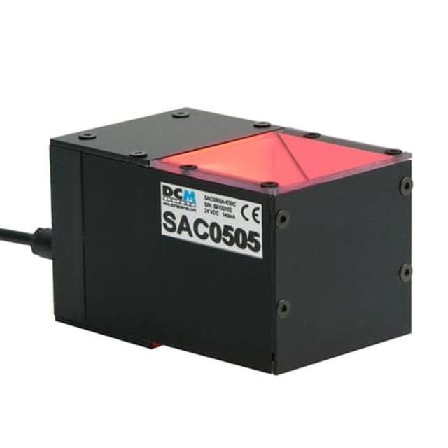
The FLV-CL30 belongs to Omron's FLV Series standard-model coaxial light lineup and uses a half-mirror/absorption-plate assembly to project diffuse, on-axis illumination ideal for inspecting scratches on highly reflective surfaces, reading laser-marked 2D codes, and detecting positioning marks. The illuminated area is 24×25 mm with an outer housing diameter of 32 mm and an overall height of 59.5 mm, weighing 110 g. Power consumption is 2.4 W for white/blue variants and 1.4 W for the red variant; all variants are powered and controlled via a compatible Omron FLV-TCC or FLV-ATC camera-mount lighting controller with a 0.8 m integrated cable. LED safety classification is Risk Group 1 per IEC 62471, and the unit is rated IP20 for standard factory-floor use.
The Omron FLV-CL30 is a coaxial (axial-diffuse) LED light unit built around a half-mirror, diffusion-plate, and absorption-plate optical assembly that projects illumination directly down the camera's optical axis. This geometry is the defining feature for inspecting highly reflective or mirror-finish workpieces: because the light travels coaxially with the lens, flat specular surfaces return a uniform, bright field back to the sensor while raised or recessed defects, scratches, and surface breaks scatter light away and appear as dark contrast against the bright background. The 24 x 25 mm illuminated area fits neatly within the working envelope of a 32 mm outer-diameter, 59.5 mm tall housing, making it straightforward to mount close to compact camera-lens assemblies without mechanical interference. At 110 g and fabricated in aluminum alloy, the unit is light enough for robot-arm or moving-gantry mounting without adding meaningful dynamic load.
Three wavelength options — white, red (635 nm typical), and blue (460 nm typical) — let integrators tune spectral contrast to the workpiece material and camera sensor. The 635 nm red variant runs at 1.4 W, making it the most power-efficient choice; the white and blue variants draw 2.4 W. All variants operate in continuous mode and, when controlled through a compatible Omron FLV-TCC or FLV-ATC camera-mount lighting controller via the integrated 0.8 m cable, also support triggered (strobe) mode, which extends LED lifetime and allows higher instantaneous brightness without exceeding thermal limits.
The unit carries an IP20 protection rating, which is appropriate for enclosed factory-floor stations free from liquid ingress but not for wash-down or heavy coolant environments. Operating temperature spans 0 to +50 degrees C (storage -15 to +60 degrees C), covering normal automated-inspection booth conditions. LED safety classification is Risk Group 1 per IEC 62471, meaning no special laser-style enclosure or interlocking is mandated, which simplifies safety documentation. Because power and control are delivered entirely through the FLV controller interface — no separate power supply or PWM driver is needed — wiring at the cell level is minimal, and brightness or strobe timing adjustments are made at the controller rather than by rewiring the light head itself.
Best for
Reading laser-marked, dot-peened, or chemically-etched 2D Data Matrix and QR codes on polished or brushed metal surfaces, where flat-coaxial illumination maximises mark-to-background contrast across a consistent 24 x 25 mm field.
Scratch and surface-blemish detection on mirror-finish components such as semiconductor wafers, glass substrates, polished bearing races, or electroplated automotive trim, where the coaxial geometry makes surface discontinuities appear as dark features against a uniformly bright background.
Positioning-mark detection and robot guidance on reflective PCBs, lead frames, or precision-machined datum features, where a stable, glare-free illuminated field enables reliable sub-pixel centroid measurement.
Industrial OCR and OCV on product labels, embossed or engraved part numbers, and date codes on shiny packaging where conventional ring or dome lights would create specular hotspots that degrade character recognition.
Compact inspection cells — particularly camera-mount or close-coupled configurations — where the 32 mm diameter and 110 g mass allow the light to be mounted directly to the lens or camera bracket without adding bulk or requiring a separate light stand.
Selection notes
Working distance and illuminated area must be matched to the camera's field of view: the FLV-CL30 delivers a fixed 24 x 25 mm illuminated area, so the lens focal length and camera-to-part distance should be chosen such that the field of view does not substantially exceed this footprint — overshooting the illuminated area will produce uneven brightness at field edges.
A compatible Omron FLV-TCC or FLV-ATC controller is mandatory; the light has no standalone power input. Confirm controller availability and the operating mode (continuous or triggered strobe) required by the application before specifying the full system.
IP20 rating limits deployment to clean, dry enclosures. Applications involving coolant mist, wash-down cycles, or heavy dust should evaluate whether an enclosure or alternative lighting product with a higher IP rating is required.
Wavelength selection should be driven by the camera sensor type and workpiece spectral reflectance: the 635 nm red variant is the lowest-power option at 1.4 W; the white and blue (460 nm) variants draw 2.4 W and may be preferred when the target material or inspection task produces better contrast under those wavelengths.
The 0.8 m integrated cable fixes the maximum separation between the light head and the controller; plan the cell layout so the controller can be mounted within that reach of the camera/lens assembly, or use a cable extension if the controller must be located further away in the control cabinet.
These steps take an Omron Sentech (STC) camera from the box to a stable first image and on to your own application. They apply across the GigE Vision, USB3 Vision and CoaXPress STC families; the interface only changes how you cable and power the camera.
Download and install the Sentech SDK on the host PC. The package provides StViewer, the viewing and configuration software you use to bring the camera up, and StApi, the programming SDK you integrate later. Because the cameras are GenICam/GenTL-compliant, StApi also registers a GenTL producer, so any GenICam-compliant third-party vision software can discover and drive the camera as an alternative front end.
2. Cable, power and connect the camera
Connect according to the interface. GigE Vision: link to a Gigabit NIC (use PoE or the separate power input) and put the camera and host on the same subnet; for USB3 Vision use a USB 3.x port and a certified cable; for CoaXPress (STC) connect to a CoaXPress frame grabber, which also supplies Power-over-Coax. Then open StViewer and let it enumerate the camera. If a GigE camera does not appear, check the IP configuration and firewall, and on USB3 confirm the host bandwidth and driver.
3. Configure exposure, gain and white balance
Open the device in StViewer and start a live stream. Set exposure and gain for a well-exposed, low-noise image: raise exposure first and only add gain when more light or a faster shutter is not an option, keeping exposure short enough to freeze motion on global-shutter models. On colour cameras, run white balance under your actual production lighting. Adjust the lens aperture and focus on a representative target before tuning anything else.
4. Set the trigger and grab a first image
Start in free-run (continuous) acquisition to confirm a clean, stable image. For inline inspection switch to hardware or software triggering: select the trigger source, set the active edge and any delay, and wire the strobe or illumination to the camera's I/O so lighting fires with each exposure. Acquire and save a frame in StViewer; this saved image is your reference for the SDK stage and for downstream inspection.
5. Move to the StApi SDK (or any GenICam software)
Once the image is stable, reproduce the same settings in code. Use StApi to open the device, apply the GenICam features you validated in StViewer (exposure, gain, trigger, pixel format) and grab frames into your application via the bundled C++, C, C#/.NET or Python interfaces; the included samples are the fastest starting point. Prefer a different stack? The same GenICam/GenTL camera works with third-party vision libraries. With a reliable feed, you can route it into a deep-learning inspection such as Rosepetal for AI-based defect detection.
Frequently asked questions
Yes, a controller is required — the FLV-CL30 has no standalone power input. It is designed to work exclusively with Omron FLV-TCC or FLV-ATC series controllers, connected via the light's integrated 0.8 m cable.
Yes, the FLV-CL30 supports both continuous and triggered (strobe) operation via a compatible FLV-TCC or FLV-ATC controller. Strobe mode allows the controller to drive higher instantaneous brightness within the LED's thermal limits and enables synchronisation with camera exposure.
The illuminated area is fixed at 24 x 25 mm. There is no zoom or adjustable aperture in the FLV-CL30; the field of view should be matched to this area through lens focal length and working distance selection.
The red (635 nm typical) variant is a common choice for laser-marked codes on metal, as 635 nm light can enhance contrast between laser-oxidised or ablated marks and the surrounding metal surface, and it runs at the lower 1.4 W consumption. White or blue variants may be evaluated if the specific metal finish or code type produces better contrast under those wavelengths.
No. The IP20 rating protects only against solid objects larger than 12.5 mm and provides no liquid ingress protection. It is rated for clean, dry, enclosed factory-floor use within an operating temperature of 0 to +50 degrees C.