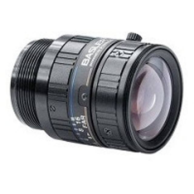
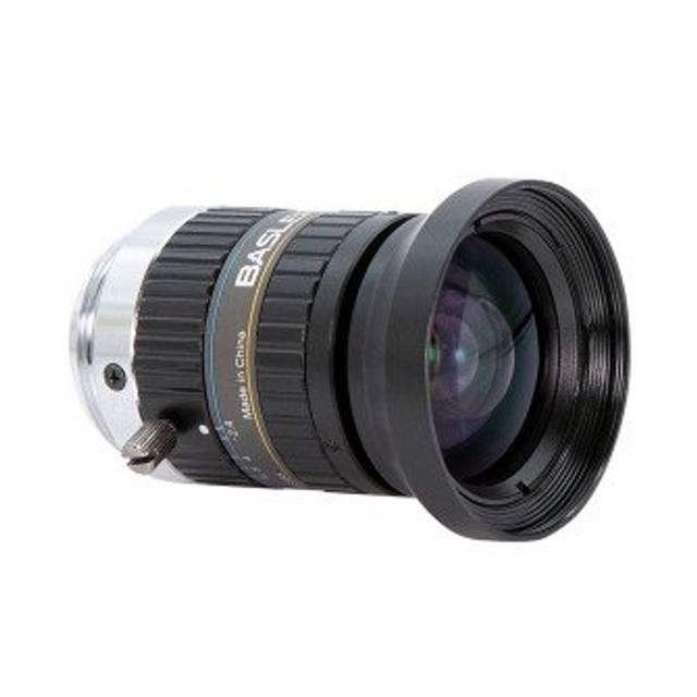
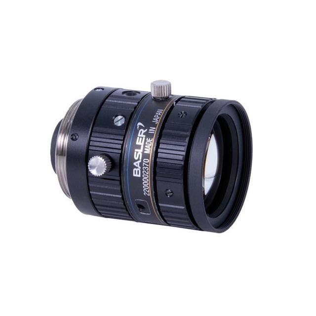
The Omron 3Z4S-LE VS-MC15 is a magnification-changeable macro lens in the VS-MC series, designed for industrial machine vision applications requiring low distortion and vibration resistance. It provides a variable magnification range of 0.03x to 0.30x, corresponding to working distances of 492.3 mm (0.03x) down to 42.3 mm (0.30x). The lens uses a standard C-mount interface, supports up to 2/3" sensors, and is available in Open (F2.0), F5.6, and F8 iris configurations. Maximum TV distortion is kept below 0.137% across the magnification range, and the filter thread is M27.0.
Brand
Omron / Sentech
Focal length
15 mm
Lens mount
C-Mount
Aperture (f-number)
F2.0 (open); F5.6; F8
Image circle / max sensor
2/3" (11 mm)
Telecentric
No
Magnification
0.03x–0.30x
Working distance
42.3–492.3 mm
Weight
51 g
Dimensions
Ø31 mm (MAX) × L 25.4 mm (0.03x) to 29.5 mm (0.30x)
The VS-MC15 is a 15 mm focal length, C-mount macro lens offering a continuously variable magnification range of 0.03x to 0.30x — a ten-to-one span that lets a single lens body cover everything from wide-area label verification at 492.3 mm working distance down to tight component inspection at 42.3 mm, simply by racking the barrel. That working-distance range (42.3 mm at 0.30x, 492.3 mm at 0.03x) is the defining practical advantage here: installers can lock the magnification to the field of view the application demands, then position the camera at the mechanically convenient distance dictated by the cell layout, rather than designing the fixture around a fixed-WD lens. The C-mount interface and a maximum image circle of 2/3" (11 mm) mean it pairs directly with the broad installed base of 2/3" and smaller sensors without vignetting concerns.
Aperture choices are F2.0 open, F5.6, and F8. The F2.0 open stop offers the highest light throughput, which matters when line speeds are fast or when lighting power is constrained; F5.6 and F8 trade some brightness for improved depth of field and reduced residual aberrations at the edges of the image circle — useful when part surfaces are not perfectly flat or when the lens is pushed toward the high-magnification end of its range. TV distortion is held to a maximum of 0.137% across the full magnification sweep, a figure low enough to support dimensional measurement and character verification tasks where geometric accuracy of the projected image is a system error contributor. The lens is not telecentric, so perspective error will increase when parts stand off the focal plane; applications demanding sub-pixel dimensional repeatability on tall or stepped features should factor this in and control part-height variation or supplement with telecentric alternatives.
The VS-MC15's vibration-resistant construction directly addresses a common factory-floor failure mode: gradual shift of magnification or focus caused by mechanical vibration working loose a conventional helicoid barrel. At 51 g and a maximum barrel diameter of 31 mm, the lens adds negligible mass and moment arm to a C-mount camera head. Physical length changes from 25.4 mm at 0.03x to 29.5 mm at 0.30x — a 4.1 mm extension — so installers should verify clearance at the high-magnification setting. The M27.0 filter thread accepts polarising, bandpass, or ND filters for lighting optimisation without adapters.
Best for
Flexible-magnification inspection cells where a single lens must serve multiple part sizes or product changeovers without a physical lens swap — the 0.03x–0.30x range covers component-level detail through full-label fields of view.
Label, date-code, and OCR/OCV verification on packaging lines where the 492.3 mm maximum working distance allows over-the-conveyor mounting with sufficient clearance for tall product, while distortion below 0.137% keeps character geometry accurate.
Dimensional gauging of small machined or moulded parts in electronics, semiconductor, automotive, and metal-fabrication contexts where low TV distortion and stable, vibration-resistant focus are required for repeatable pixel-to-mm calibration.
Surface and defect inspection on flat or near-flat parts — pharma blister packs, PCB substrates, stamped metal panels — where the variable working distance lets the lens be set for the magnification that resolves the smallest defect of interest while keeping the camera within the cell envelope.
Multi-application R&D or pilot lines where engineers need to characterise imaging performance across a range of fields of view without procuring multiple fixed-macro lenses; the single VS-MC15 covers the field.
Selection notes
Sensor size compatibility: the 2/3" image circle is the upper limit — cameras with sensors larger than 2/3" will see vignetting. Confirm your camera sensor is 2/3" or smaller before specifying.
Non-telecentric geometry: at the 0.30x end (42.3 mm WD) any part height variation introduces magnification error. For tight dimensional tolerances on stepped or three-dimensional parts, quantify the expected height variation and determine whether the resulting measurement error is within budget, or whether a telecentric lens is needed instead.
Aperture selection trade-off: the three iris configurations (F2.0 open, F5.6, F8) are distinct product variants, not a continuous or field-adjustable iris. Plan the lighting design around the chosen configuration — F8 in particular will require proportionally more illumination or longer exposure, which must be compatible with line speed.
Barrel length change: the lens extends 4.1 mm from its shortest to longest configuration (25.4 mm at 0.03x to 29.5 mm at 0.30x). Verify that the camera-lens assembly does not contact guarding, part fixtures, or conveyor structure at the maximum-magnification setting.
Filter thread: the M27.0 filter thread enables direct attachment of polarising or narrow-bandpass filters, which can significantly improve contrast on reflective or specular surfaces common in metal, semiconductor, and pharma inspection — factor filter availability and cost into the system BOM.
Specifications: General
Brand
Omron / Sentech
Specifications: Optical
Focal length
15 mm
Lens mount
C-Mount
Aperture (f-number)
F2.0 (open); F5.6; F8
Image circle / max sensor
2/3" (11 mm)
Telecentric
No
Magnification
0.03x–0.30x
Working distance
42.3–492.3 mm
Specifications: Mechanical
Weight
51 g
Dimensions
Ø31 mm (MAX) × L 25.4 mm (0.03x) to 29.5 mm (0.30x)
Applications this camera is commonly selected for. Open one to see the full recommended hardware and approach.
Matched automatically by: camera mount fits the lens mount · camera sensor is covered by the lens image circle — this lens: C-Mount · 2/3" (11 mm) image circle.
By category
All 758Area scan cameras 622High-speed cameras 108High-resolution cameras 28
By brand
All 758Omron / Sentech 297Basler 242iRAYPLE 200Datalogic / Datasensing 19
These steps take an Omron Sentech (STC) camera from the box to a stable first image and on to your own application. They apply across the GigE Vision, USB3 Vision and CoaXPress STC families; the interface only changes how you cable and power the camera.
Download and install the Sentech SDK on the host PC. The package provides StViewer, the viewing and configuration software you use to bring the camera up, and StApi, the programming SDK you integrate later. Because the cameras are GenICam/GenTL-compliant, StApi also registers a GenTL producer, so any GenICam-compliant third-party vision software can discover and drive the camera as an alternative front end.
2. Cable, power and connect the camera
Connect according to the interface. GigE Vision: link to a Gigabit NIC (use PoE or the separate power input) and put the camera and host on the same subnet; for USB3 Vision use a USB 3.x port and a certified cable; for CoaXPress (STC) connect to a CoaXPress frame grabber, which also supplies Power-over-Coax. Then open StViewer and let it enumerate the camera. If a GigE camera does not appear, check the IP configuration and firewall, and on USB3 confirm the host bandwidth and driver.
3. Configure exposure, gain and white balance
Open the device in StViewer and start a live stream. Set exposure and gain for a well-exposed, low-noise image: raise exposure first and only add gain when more light or a faster shutter is not an option, keeping exposure short enough to freeze motion on global-shutter models. On colour cameras, run white balance under your actual production lighting. Adjust the lens aperture and focus on a representative target before tuning anything else.
4. Set the trigger and grab a first image
Start in free-run (continuous) acquisition to confirm a clean, stable image. For inline inspection switch to hardware or software triggering: select the trigger source, set the active edge and any delay, and wire the strobe or illumination to the camera's I/O so lighting fires with each exposure. Acquire and save a frame in StViewer; this saved image is your reference for the SDK stage and for downstream inspection.
5. Move to the StApi SDK (or any GenICam software)
Once the image is stable, reproduce the same settings in code. Use StApi to open the device, apply the GenICam features you validated in StViewer (exposure, gain, trigger, pixel format) and grab frames into your application via the bundled C++, C, C#/.NET or Python interfaces; the included samples are the fastest starting point. Prefer a different stack? The same GenICam/GenTL camera works with third-party vision libraries. With a reliable feed, you can route it into a deep-learning inspection such as Rosepetal for AI-based defect detection.
Frequently asked questions
The VS-MC15 covers a maximum image circle of 2/3" (11 mm). It will work without vignetting on cameras with 2/3" and smaller sensors. Sensors larger than 2/3" are not supported.
Working distance runs from 492.3 mm at the lowest magnification (0.03x) down to 42.3 mm at the highest magnification (0.30x). This roughly 450 mm span means the camera-to-part distance changes substantially across the magnification range — the mounting position must be set for the magnification the application requires.
It can support dimensional measurement where measurement uncertainty budgets are compatible with a non-telecentric design. TV distortion is guaranteed below 0.137%, which is low enough for many gauging tasks. However, because the lens is not telecentric, any variation in part height relative to the focal plane will introduce a proportional magnification error. Applications with tight dimensional tolerances and significant part-height variation should evaluate whether this error is acceptable or whether a telecentric lens is required.
The lens is available in three iris configurations: Open (F2.0), F5.6, and F8. F2.0 maximises light throughput and enables the shortest exposure times, benefiting high-speed lines or low-power lighting setups. F5.6 and F8 increase depth of field and can reduce off-axis aberrations, at the cost of needing more illumination. Each configuration is a separate product variant selected at purchase, not adjustable in the field.
The VS-MC15 is designed to maintain its set magnification and focus position under factory-floor vibration, which in a conventional lens can gradually shift the barrel and drift calibration. In practice this reduces the frequency of recalibration events and makes the lens more suitable for mounting on machinery subject to regular vibration from nearby actuators, conveyors, or presses.