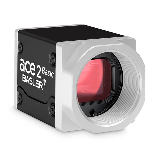
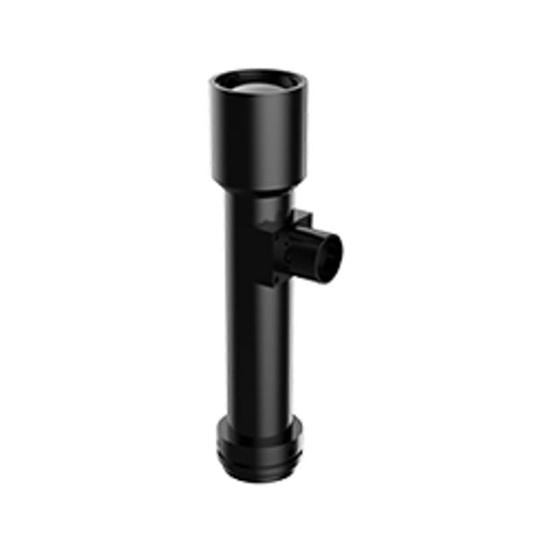
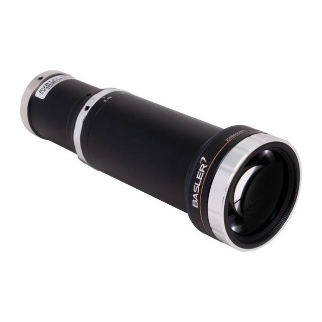
The iRAYPLE MTL11-11020XD-C is a high-precision object-side telecentric lens designed for industrial machine vision measurement and positioning applications. It delivers a fixed 2.0× magnification with a 110mm±3% working distance covering the 2/3-inch sensor format (φ11mm image circle). Key optical performance includes a resolution of 4.5μm, image-side MTF greater than 0.3 at 75 lp/mm, telecentricity below 0.15°, and optical distortion below 0.023%. The C-mount lens features an integrated coaxial illumination port and supports 5MP and 9MP cameras, with a compact body of 129.6mm × φ30mm.
The iRAYPLE MTL11-11020XD-C is a fixed 2.0x magnification object-side telecentric lens built for precision dimensional measurement in industrial machine vision. Its defining optical characteristic — object-side telecentricity below 0.15° — means that the chief ray in object space travels nearly parallel to the optical axis, so the projected image size of a part does not change as the part moves axially within the depth of field. This eliminates the perspective error that afflicts conventional lenses and is the fundamental requirement for any gauging task where a camera must distinguish fractions of a millimetre across a production line. The 110mm ±3% working distance places the lens far enough from the subject to allow fixtures, conveyor surfaces, or back-lighting panels to coexist without mechanical conflict, while the compact 129.6mm × ⌀30mm body keeps the overall optical assembly manageable for integration into tight inspection cells.
The optical performance figures are engineered for high-pixel-count sensors: a 4.5 µm resolution limit and image-side MTF greater than 0.3 at 75 lp/mm across the full ⌀11mm (2/3-inch) image circle mean fine features are rendered with usable contrast all the way to the corners of a 5MP or 9MP sensor — the two formats the lens is rated for. Optical distortion is held below 0.023%, an exceptionally tight figure that means a straight edge or pitch measurement taken near the image periphery will carry no more than 0.023% geometric error from the lens itself; downstream calibration and software correction burdens are therefore minimal. The F13.5 aperture is characteristic of telecentrics: the stopped-down iris is part of what enforces telecentricity, and at 2.0x magnification it simultaneously provides a usable depth of field for slightly uneven or warped parts. The C-mount interface is the standard for 2/3-inch format cameras, giving broad compatibility with area-scan sensors from virtually every major manufacturer.
A standout integration feature is the built-in coaxial illumination port. Coaxial (on-axis) illumination is the preferred lighting geometry for flat, specular, or mirrored surfaces — it returns maximum brightness from polished metal, silicon wafers, PCB pads, and glass panels while suppressing surrounding scatter. Having this port integrated into the lens body eliminates the need for a separate beam-splitter cube in the optical path and reduces system length, cost, and alignment complexity. The lens operates across -10°C to +50°C, covering standard factory floor conditions. Because the working distance is fixed (the design assumes a factory-calibrated standoff), installers should treat the 110mm ±3% tolerance as the allowable part-height variation across the field — parts that fall outside this ±3.3mm band will show magnification and focus error and should be rejected upstream or re-fixtured.
Best for
Precision dimensional gauging of machined metal parts, stamped connectors, and injection-moulded components where measurements must be traceable to sub-pixel accuracy and perspective error cannot be tolerated
Semiconductor and PCB inspection — solder joint coplanarity, pad pitch verification, die placement, and lead-frame geometry — where polished or specular surfaces benefit from the integrated coaxial illumination port
Electronic component sorting and positioning, such as verifying IC package dimensions and lead counts on a pick-and-place line, where 5MP or 9MP sensors paired at 2.0x magnification deliver fine spatial sampling over a small field of view
Automotive precision parts inspection — valve seats, fuel injector nozzles, gear teeth, or bearing races — where the 110mm working distance allows clearance for part fixtures and the low 0.023% distortion eliminates the need for per-image geometric correction
Flat glass, wafer, or optical element surface inspection where coaxial back-illumination or on-axis reflected illumination through the integrated port is required to reveal edge chips, scratches, or coating defects on specular substrates
Selection notes
Sensor format and resolution ceiling: the ⌀11mm image circle covers the 2/3-inch format (diagonal ~11mm). Pairing with a 1-inch or larger sensor will result in vignetting at the corners, as the 1-inch format has a diagonal of approximately 16mm, which exceeds the image circle. The lens is rated to 9MP on 2/3-inch; verify that the 4.5 µm optical resolution limit is finer than twice your sensor pixel pitch to avoid the lens becoming the resolution bottleneck.
Working distance is fixed, not adjustable: unlike a standard entocentric lens with a focus ring, the telecentric design locks the working distance at 110mm ±3%. Fixturing must position the part within this ±3.3mm axial band. If your application involves height variation larger than this, consider a lens with a longer depth of field or add a height-normalization fixture stage.
Coaxial illumination integration: the built-in port accepts coaxial light sources matched to the ⌀30mm body. Confirm the coaxial illuminator you intend to use is compatible with the port geometry before ordering. This port replaces an external beam-splitter and keeps the system compact, but it also means diffuse or ring illumination must be added as a secondary source if shadowless brightfield is insufficient for your surface type.
Aperture and exposure trade-off: F13.5 is a relatively small aperture, which at visible wavelengths means longer exposure times compared with a fast entocentric lens. Confirm that your camera's sensor sensitivity and the coaxial illuminator's output power are sufficient to achieve the exposure times needed for your line speed. Strobed illumination is recommended for moving parts to freeze motion without motion blur.
C-mount mechanical clearance: the lens body is 129.6mm long. When mounted to a camera with a standard C-mount flange-to-sensor distance of 17.526mm, the total camera-plus-lens depth exceeds 147mm. Verify this fits within your gantry or inspection station Z-axis travel and that no part of the fixture or conveyor can contact the front element at the 110mm working distance standoff.
Specifications: General
Brand
iRAYPLE
Specifications: Optical
Lens mount
C-Mount
Magnification
2.0×
Working distance
110mm ±3%
Image circle / max sensor
φ11mm (2/3")
Aperture (f-number)
F13.5
Telecentric
Yes (object-side telecentric)
Optical resolution
Up to 9MP
Specifications: Environment
Operating temperature
-10°C to +50°C
Specifications: Mechanical
Dimensions
129.6mm × φ30mm
Applications this camera is commonly selected for. Open one to see the full recommended hardware and approach.
Matched automatically by: camera mount fits the lens mount · camera sensor is covered by the lens image circle — this lens: C-Mount · φ11mm (2/3") image circle.
By category
All 758Area scan cameras 622High-speed cameras 108High-resolution cameras 28
By brand
All 758Omron / Sentech 297Basler 242iRAYPLE 200Datalogic / Datasensing 19
Follow these steps to bring up your iRAYPLE camera, capture a first image, and move from the viewer to your own application. The flow is the same across the A, AE, AX and L series; only the physical interface differs.
Download and install the iRAYPLE machine-vision SDK together with its viewer client for your operating system. The installer provides the camera drivers, the GenTL producer, and the viewer you will use for first light. For GigE Vision models, also install or enable the bundled filter/performance driver on the network adapter to maximize throughput.
2. Connect the camera to the correct interface
Wire the camera to its matching host interface: a dedicated Gigabit (or 10 GigE) NIC for GigE Vision models, a USB3 Vision port with a quality cable for USB3 models, or a frame grabber for CoaXPress models. Power the camera (PoE, USB bus power, or PoCXP / external supply as applicable). For GigE Vision, put the NIC and camera on the same subnet and, where supported, enable jumbo frames.
3. Detect and open the camera in the viewer
Launch the iRAYPLE viewer, run device enumeration, and select your camera from the discovered list. Open it to load the device feature tree (GenICam node map). If a GigE camera is found but cannot be opened, correct the IP configuration so the camera and NIC are in the same address range.
4. Set exposure, gain and trigger, then grab a first image
Start with continuous (free-run) acquisition under stable lighting. Adjust exposure time and gain for a well-exposed, low-noise image, set the pixel format (e.g. Mono8 or a Bayer/RGB format), and tune white balance on color models. Once the live image looks correct, switch trigger mode to hardware or software trigger to synchronize capture with your process, and verify a single triggered frame.
5. Move from the viewer to the SDK or a GenICam library
With imaging confirmed, reproduce the same settings in code using the SDK's C/C++ or Python API: enumerate, open, configure the relevant GenICam features, register a frame callback or grab loop, and convert frames to your pipeline's buffer format. Since the cameras are GenICam/GenTL-compliant, you can alternatively drive them from a third-party GenICam vision library. From here a stable image stream can feed a deep-learning inspection step such as Rosepetal for automated quality control.
Frequently asked questions
The lens is rated for up to 9MP on the 2/3-inch sensor format. Its 4.5 µm optical resolution means it can resolve features down to that spatial scale, so it can fully utilise sensors with pixel pitches of approximately 2.25 µm or larger (the Nyquist requirement relative to the 4.5 µm limit). Operating with sensors finer than that will yield no additional resolved detail from the lens.
Because this is an object-side telecentric lens with telecentricity below 0.15°, the change in apparent magnification due to axial part displacement within the ±3% working distance tolerance is negligible — this is precisely the advantage of telecentric optics over conventional lenses. Outside the ±3.3mm band, focus and telecentricity error will grow, and measurements should not be trusted.
No. The image circle is ⌀11mm, which matches the 2/3-inch format (diagonal ~11mm). A 1-inch sensor has a diagonal of approximately 16mm, which exceeds the image circle and causes corner vignetting and potential distortion outside the ⌀11mm coverage area. Smaller formats such as 1/1.8-inch (diagonal ~8.9mm) fit within the image circle without vignetting. The lens should be paired with 2/3-inch or smaller format sensors.
The specifications list a fixed working distance of 110mm ±3% and a fixed aperture of F13.5. Telecentric lenses are typically fixed in both focus and aperture to preserve the telecentric ray geometry. Installers should set the mechanical standoff precisely and not expect to refocus in the field.
The datasheet specifies optical distortion below 0.023% and MTF greater than 0.3 at 75 lp/mm across the full ⌀11mm image circle, confirming these figures apply end-to-end. No wavelength restriction is stated in the available specifications, so the lens targets the standard visible spectrum used with industrial area-scan cameras; if narrowband or UV/NIR illumination is required, confirm spectral transmission with iRAYPLE before committing to a design.