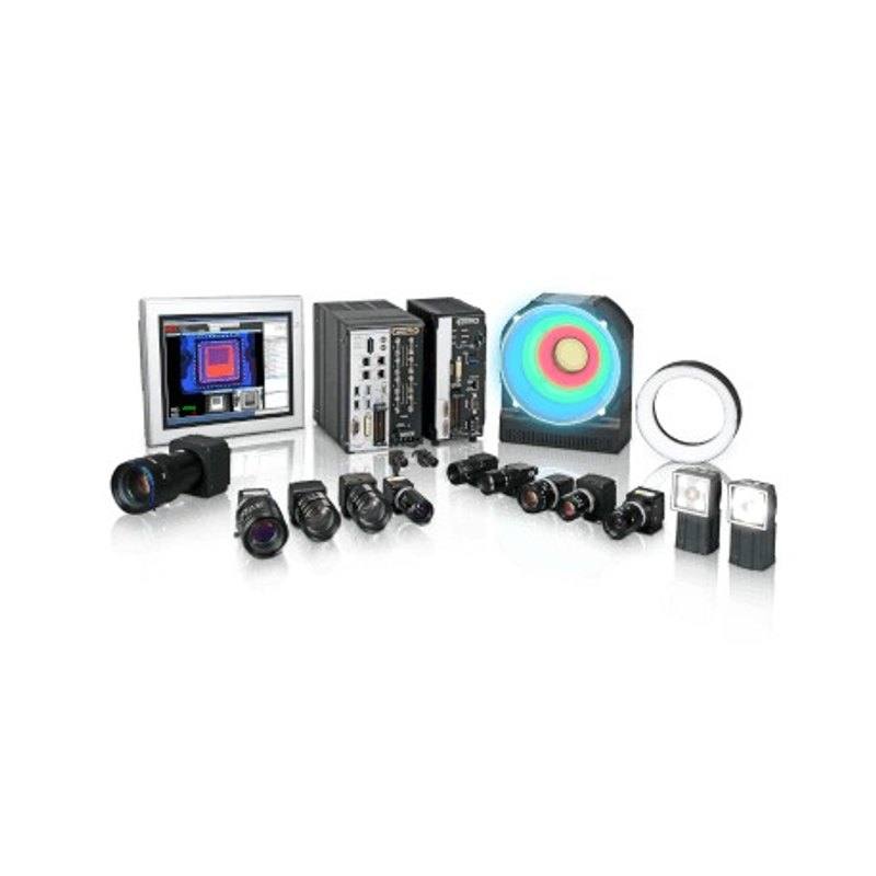
The FLV-TCC4 is a compact 4-channel lighting controller that mounts directly onto Omron FH-S/FZ-S series cameras and controls up to four FLV series standard lights. Power is supplied either through the camera (12 V) or an external 24 VDC supply, with a maximum current consumption of 1.5 A. The controller supports both continuous and trigger lighting modes with digital luminance control via PWM (100 kHz, 255 levels) or voltage adjustment, and connects to the vision system via the camera connection cable without additional ladder programming. Degree of protection is IP20 and operating temperature is 0 to +50°C.
Brand
Omron / Sentech
Lighting type
controller
Mode
Continuous and Trigger (strobe)
Controller required
No (this unit IS the controller)
Supply voltage
12 VDC (from camera) or 24 VDC ±10% external
Power consumption
15 W max. (4ch total, with 24 V external supply trigger lighting)
Driver technology
Constant voltage drive; PWM luminance control at 100 kHz, 255 levels; voltage light adjustment 255 levels
Connection
Camera connection cable (direct connection to camera); 24 V external supply via terminal block; lighting via proprietary connectors
Housing material
Aluminum case and camera mount plate; FPVC cable
Dimensions
96 × 40 × 20 mm (W × H × D), per dimensional drawing
The FLV-TCC4 is a 4-channel camera-mount lighting controller purpose-built to pair with Omron FH-S and FZ-S series vision systems, integrating directly onto the camera body to form a self-contained capture head. At 96 x 40 x 20 mm and 130 g including the aluminum mount plate, it adds negligible bulk to the camera assembly while eliminating the dedicated lighting controller panel and its associated wiring runs. Power is drawn either from the camera's own 12 VDC rail or from a separate 24 VDC ±10% external supply, with total consumption across all four channels capped at 15 W under 24 VDC external supply in trigger mode. For integrators working in confined cells or on robot arms, this consolidation of power and signal into the camera connection cable is a material reduction in cable management complexity and potential failure points.
Luminance is regulated through constant-voltage drive with 100 kHz PWM at 255 discrete levels, or alternatively via voltage-based light adjustment at the same 255-level resolution. Both methods give the vision system fine-grained brightness control without external analog wiring. The controller supports continuous operation and trigger (strobe) modes across all four channels, meaning up to four FLV series lights can be fired independently or in concert, selectable per inspection step directly from the FH-S/FZ-S camera software without additional PLC ladder programming. This tight software integration is particularly valuable on multi-illumination inspection stations — such as those alternating between coaxial, low-angle, and backlight channels — where synchronizing lighting sequences to camera exposure traditionally requires external I/O logic.
The aluminum case and mount plate provide structural rigidity appropriate for fixed-mount industrial installations, and the FPVC cable resists oils and mild solvents common on production floors. IP20 protection and an operating range of 0 to +50°C suit climate-controlled indoor factory environments; the rating does not cover wash-down or heavy particle contamination, so installations in food or pharma areas with aggressive cleaning protocols will need supplemental enclosure protection for the controller, while the lights themselves may carry higher ingress ratings. Because the FLV-TCC4 is specific to the FLV series standard light range, the full lighting channel budget — geometry, wavelength, working distance — is determined by light head selection, leaving the FLV-TCC4 to handle solely power delivery, dimming, and trigger timing.
Best for
Multi-illumination inline inspection stations using Omron FH-S or FZ-S cameras, where two to four lighting geometries (e.g., coaxial, ring, bar, backlight) must be sequenced per frame without a separate lighting controller cabinet
Robot-mounted or articulating camera heads where minimizing cable count and head mass is critical and all four lighting channels must share a single routed cable bundle back to the robot controller
Retrofit upgrades to existing Omron FH-S/FZ-S vision cells where panel space is constrained and a standalone lighting controller cannot be accommodated
Applications requiring precise, repeatable luminance calibration — such as surface defect inspection, OCR/OCV, or dimensional gauging — that benefit from 255-level PWM brightness steps and software-addressable control
Compact fixed-mount inspection heads in electronics, semiconductor, or pharmaceutical assembly where a clean, integrated camera-lighting module simplifies installation validation and change management
Selection notes
Camera compatibility is mandatory: the FLV-TCC4 connects only through the Omron FH-S/FZ-S camera connection cable and controls only FLV series standard lights — confirm both your camera model and light head model are within the supported range before ordering
Total channel power is 15 W maximum across all four channels under 24 VDC external supply in trigger mode; when summing the power draw of the selected FLV light heads, stay within this envelope — particularly if driving high-current bar or dome lights on multiple channels simultaneously
The 12 VDC camera-supply option is convenient for low-power single-light configurations, but heavy multi-channel or strobe-intensive loads should use the dedicated 24 VDC ±10% external terminal-block supply to avoid drawing down the camera's power rail
IP20 protection covers only light finger-touch ingress; installations near coolant spray, wash-down zones, or heavy swarf should house the controller in a separate sealed enclosure or relocate it away from the immediate process environment
No additional PLC or ladder programming is required for lighting triggers — the controller is managed entirely through the FH-S/FZ-S camera software, which simplifies commissioning but also means lighting control is not accessible from external PLCs without going through the vision system's I/O interface
Specifications: General
Brand
Omron / Sentech
Lighting type
controller
Specifications: Interface
Connection
Camera connection cable (direct connection to camera); 24 V external supply via terminal block; lighting via proprietary connectors
Specifications: Electrical
Mode
Continuous and Trigger (strobe)
Controller required
No (this unit IS the controller)
Supply voltage
12 VDC (from camera) or 24 VDC ±10% external
Power consumption
15 W max. (4ch total, with 24 V external supply trigger lighting)
Driver technology
Constant voltage drive; PWM luminance control at 100 kHz, 255 levels; voltage light adjustment 255 levels
Specifications: Environment
Operating temperature
Operating: 0 to +50°C; Storage: -15 to +60°C
IP rating
IP20 (IEC60529)
Specifications: Mechanical
Housing material
Aluminum case and camera mount plate; FPVC cable
Dimensions
96 × 40 × 20 mm (W × H × D), per dimensional drawing
Weight
Approx. 130 g (including camera mount plate)
Applications this camera is commonly selected for. Open one to see the full recommended hardware and approach.
These steps take an Omron Sentech (STC) camera from the box to a stable first image and on to your own application. They apply across the GigE Vision, USB3 Vision and CoaXPress STC families; the interface only changes how you cable and power the camera.
Download and install the Sentech SDK on the host PC. The package provides StViewer, the viewing and configuration software you use to bring the camera up, and StApi, the programming SDK you integrate later. Because the cameras are GenICam/GenTL-compliant, StApi also registers a GenTL producer, so any GenICam-compliant third-party vision software can discover and drive the camera as an alternative front end.
2. Cable, power and connect the camera
Connect according to the interface. GigE Vision: link to a Gigabit NIC (use PoE or the separate power input) and put the camera and host on the same subnet; for USB3 Vision use a USB 3.x port and a certified cable; for CoaXPress (STC) connect to a CoaXPress frame grabber, which also supplies Power-over-Coax. Then open StViewer and let it enumerate the camera. If a GigE camera does not appear, check the IP configuration and firewall, and on USB3 confirm the host bandwidth and driver.
3. Configure exposure, gain and white balance
Open the device in StViewer and start a live stream. Set exposure and gain for a well-exposed, low-noise image: raise exposure first and only add gain when more light or a faster shutter is not an option, keeping exposure short enough to freeze motion on global-shutter models. On colour cameras, run white balance under your actual production lighting. Adjust the lens aperture and focus on a representative target before tuning anything else.
4. Set the trigger and grab a first image
Start in free-run (continuous) acquisition to confirm a clean, stable image. For inline inspection switch to hardware or software triggering: select the trigger source, set the active edge and any delay, and wire the strobe or illumination to the camera's I/O so lighting fires with each exposure. Acquire and save a frame in StViewer; this saved image is your reference for the SDK stage and for downstream inspection.
5. Move to the StApi SDK (or any GenICam software)
Once the image is stable, reproduce the same settings in code. Use StApi to open the device, apply the GenICam features you validated in StViewer (exposure, gain, trigger, pixel format) and grab frames into your application via the bundled C++, C, C#/.NET or Python interfaces; the included samples are the fastest starting point. Prefer a different stack? The same GenICam/GenTL camera works with third-party vision libraries. With a reliable feed, you can route it into a deep-learning inspection such as Rosepetal for AI-based defect detection.
Frequently asked questions
The FLV-TCC4 mounts onto and draws signal from Omron FH-S and FZ-S series cameras via the camera connection cable. It is not compatible with other camera families or third-party cameras.
Up to four FLV series standard lights can be connected simultaneously across the four channels. The controller is designed specifically for the FLV standard light range; other Omron or third-party light heads are not supported.
The controller can be powered from the camera's own 12 VDC supply for lighter loads. For full multi-channel or trigger (strobe) operation the maximum draw is 15 W under 24 VDC external supply, which requires the dedicated 24 VDC ±10% external supply connected via the terminal block.
Brightness is controlled entirely through the FH-S/FZ-S vision system software using either 100 kHz PWM or voltage-based adjustment, both at 255 levels. No additional wiring, potentiometers, or PLC programming is required.
No. The controller is rated IP20, which provides only basic protection against finger contact. It is not suitable for direct exposure to liquids, wash-down, or heavy dust without an additional external enclosure.