Omron / Sentech FLV-DR3220 Direct Ring Light (32 mm)
FLV-DR3220
The FLV-DR3220 is the smallest model in Omron's FLV-DR Direct Ring Light series, featuring a 32 mm outer diameter, 10 mm inner aperture, and a 20-degree emission angle for directional illumination of small workpieces. The aluminum alloy housing incorporates a high-density LED array with an integral thermal conductor and PCB; an optional diffusion plate (FLV-DR3220DF) can be added for more uniform illumination. Power is supplied through a companion FLV-TCC or FLV-ATC lighting controller, which accepts either 12 VDC from a compatible Omron camera or 24 VDC from an external supply. Typical applications include PCB component inspection, printing and character detection, automotive part inspection, PET bottle mouth defect detection, and 1D/2D code reading.
Brand
Omron / Sentech
Lighting type
Direct Ring
Color / wavelength
White (broadband), Red (typ. 635 nm), Blue (typ. 460 nm)
Mode
Continuous and trigger lighting (via controller)
Controller required
Yes — FLV-TCC or FLV-ATC series controller required
Diffuser
No (optional diffusion plate FLV-DR3220DF available)
Inner diameter
10 mm
Emission angle
20 deg
Available wavelengths
White (W), Red (R, typ. 635 nm), Blue (B, typ. 460 nm)
Power consumption
1.3 W (Red) / 1.4 W (White, Blue)
Supply voltage
12 VDC via camera / 24 VDC external (supplied through FLV-TCC/ATC controller)
The FLV-DR3220 is the smallest model in Omron's FLV-DR Direct Ring Light series, built around a 32 mm outer diameter aluminum alloy housing that is only 16 mm tall. Its 10 mm inner aperture is sized for close-in illumination of small workpieces — PCB pads, pill prints, bottle mouths, or 1D/2D code labels. The 20-degree emission angle is the defining optical characteristic: light leaves the LED array in a tight cone that strikes the surface at a low incident angle, producing pronounced shadow relief on surface texture and edges. This directional geometry is what makes ring lights of this size effective for character contrast and micro-defect detection, while staying compact enough to fit in tight fixture envelopes where a larger co-axial or dome light would not clear the part.
Three wavelength variants ship under the same form factor — White (broadband), Red (typically 635 nm), and Blue (typically 460 nm) — giving integrators a straightforward way to tune contrast for the material at hand without changing the mechanical installation. Red at 635 nm absorbs into dark inks and carbon-filled plastics to sharpen print edges; Blue at 460 nm interacts strongly with fluorescent coatings and is the standard choice for detecting surface contamination or scratches on metallic or transparent substrates. Power consumption is modest at 1.3 W for the Red variant and 1.4 W for White and Blue, which the integral thermal conductor and PCB assembly inside the aluminum housing dissipates passively with no active cooling required. An optional diffusion plate (FLV-DR3220DF) can be added to soften the beam when a part's surface finish makes specular hot-spots a problem — useful for shiny injection-moulded caps or metallic carrier tape.
The FLV-DR3220 is not a stand-alone device: it requires an Omron FLV-TCC or FLV-ATC lighting controller, connected via the 0.8 m integral cable. Those controllers accept power from a compatible Omron camera's 12 VDC output or from an external 24 VDC supply, and they expose continuous and triggered lighting modes to the vision system. Triggered mode is the high-value operating path: the controller strobes the LEDs in synchrony with the camera's exposure window, allowing much higher instantaneous brightness than continuous operation can sustain while keeping average power and thermal load low. For a 32 mm ring weighing 60 g, that strobe capability makes it viable for inspecting parts on moving lines without motion blur — a task that continuous lighting at this power level could not support.
Best for
PCB component and solder-joint inspection where the 10 mm inner aperture and 20-degree beam angle produce edge shadow that distinguishes lifted or misaligned SMD components from correctly seated ones.
1D barcode and 2D data-matrix code reading on small labels or directly marked parts — the directional ring illumination generates the contrast gradient that area-scan cameras and code-reading algorithms depend on.
PET bottle mouth and pharmaceutical blister defect detection, where the compact form factor mounts close to the lens axis and the choice of Red or Blue wavelength can be matched to cap or foil color to maximize defect visibility.
Printed character OCR and OCV on product markings, date codes, or component labels, where Red light absorbs ink on white substrates to sharpen character edges, and Blue light reveals faint laser engravings on reflective metal surfaces.
Automotive and electronics surface inspection for scratches, burrs, or contamination on small stamped or machined metal parts, using Blue illumination at 460 nm to maximize scatter from surface discontinuities.
Selection notes
Controller is mandatory — budget for an FLV-TCC or FLV-ATC unit alongside the light head; neither 12 VDC nor 24 VDC can be wired directly to the FLV-DR3220 without the controller in the signal path, and triggered strobe mode is only accessible through the controller interface.
The 10 mm inner aperture defines the opening through which the workpiece is illuminated at close range: confirm your fixture geometry and working distance are compatible before ordering. The light is designed for close working distances typical of macro and telecentric lenses covering small fields of view.
Choose wavelength based on the spectral response of your sensor and the reflectance of the target material: White is the safe default for broadband color cameras, Red (635 nm) maximises contrast on dark print against pale substrates when used with monochrome sensors, and Blue (460 nm) is preferred for metallic or transparent surfaces and for sensors with strong blue QE.
If your part surface is specular — polished metal, glossy plastic, glass — order the optional FLV-DR3220DF diffusion plate at the same time. Retrofitting it later is straightforward, but forgetting it means a return trip when the ring's narrow 20-degree beam produces saturated reflections that wash out the defect signal.
At 60 g and 32 mm OD the light head is light enough that vibration isolation is rarely needed, but the 0.8 m fixed cable constrains how far the controller can be placed from the inspection station; plan cable routing before finalising the fixture layout.
Specifications: General
Brand
Omron / Sentech
Lighting type
Direct Ring
Specifications: Interface
Connection
0.8 m cable to controller
Specifications: Optical
Color / wavelength
White (broadband), Red (typ. 635 nm), Blue (typ. 460 nm)
Diffuser
No (optional diffusion plate FLV-DR3220DF available)
Emission angle
20 deg
Available wavelengths
White (W), Red (R, typ. 635 nm), Blue (B, typ. 460 nm)
Specifications: Electrical
Mode
Continuous and trigger lighting (via controller)
Controller required
Yes — FLV-TCC or FLV-ATC series controller required
Power consumption
1.3 W (Red) / 1.4 W (White, Blue)
Supply voltage
12 VDC via camera / 24 VDC external (supplied through FLV-TCC/ATC controller)
Specifications: Geometry
Inner diameter
10 mm
Specifications: Mechanical
Housing material
Aluminum alloy
Dimensions
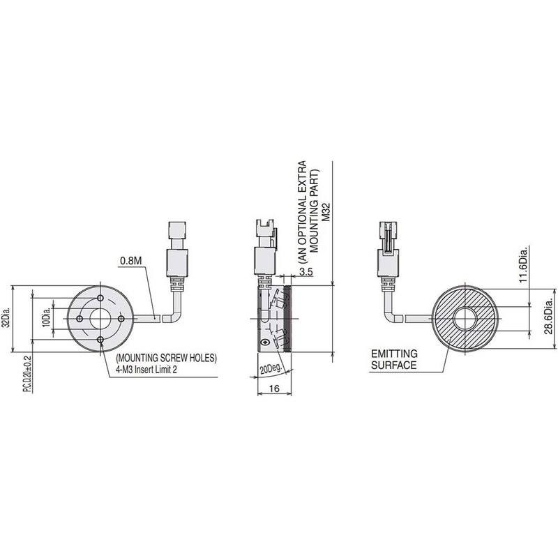
32 mm outer dia. × 10 mm inner dia. × 16 mm height
Weight
60 g
Applications this camera is commonly selected for. Open one to see the full recommended hardware and approach.
These steps take an Omron Sentech (STC) camera from the box to a stable first image and on to your own application. They apply across the GigE Vision, USB3 Vision and CoaXPress STC families; the interface only changes how you cable and power the camera.
Download and install the Sentech SDK on the host PC. The package provides StViewer, the viewing and configuration software you use to bring the camera up, and StApi, the programming SDK you integrate later. Because the cameras are GenICam/GenTL-compliant, StApi also registers a GenTL producer, so any GenICam-compliant third-party vision software can discover and drive the camera as an alternative front end.
2. Cable, power and connect the camera
Connect according to the interface. GigE Vision: link to a Gigabit NIC (use PoE or the separate power input) and put the camera and host on the same subnet; for USB3 Vision use a USB 3.x port and a certified cable; for CoaXPress (STC) connect to a CoaXPress frame grabber, which also supplies Power-over-Coax. Then open StViewer and let it enumerate the camera. If a GigE camera does not appear, check the IP configuration and firewall, and on USB3 confirm the host bandwidth and driver.
3. Configure exposure, gain and white balance
Open the device in StViewer and start a live stream. Set exposure and gain for a well-exposed, low-noise image: raise exposure first and only add gain when more light or a faster shutter is not an option, keeping exposure short enough to freeze motion on global-shutter models. On colour cameras, run white balance under your actual production lighting. Adjust the lens aperture and focus on a representative target before tuning anything else.
4. Set the trigger and grab a first image
Start in free-run (continuous) acquisition to confirm a clean, stable image. For inline inspection switch to hardware or software triggering: select the trigger source, set the active edge and any delay, and wire the strobe or illumination to the camera's I/O so lighting fires with each exposure. Acquire and save a frame in StViewer; this saved image is your reference for the SDK stage and for downstream inspection.
5. Move to the StApi SDK (or any GenICam software)
Once the image is stable, reproduce the same settings in code. Use StApi to open the device, apply the GenICam features you validated in StViewer (exposure, gain, trigger, pixel format) and grab frames into your application via the bundled C++, C, C#/.NET or Python interfaces; the included samples are the fastest starting point. Prefer a different stack? The same GenICam/GenTL camera works with third-party vision libraries. With a reliable feed, you can route it into a deep-learning inspection such as Rosepetal for AI-based defect detection.
Frequently asked questions
No. The specs explicitly state that a compatible FLV-TCC or FLV-ATC series controller is required. The 0.8 m cable connects to that controller, which in turn accepts either 12 VDC from a compatible Omron camera output or 24 VDC from an external supply. Bypassing the controller is not a supported configuration.
White, Red (typ. 635 nm), and Blue (typ. 460 nm) are separate SKUs sharing the same 32 mm OD × 10 mm ID × 16 mm H form factor and the same mounting interface, so a wavelength swap is a mechanical swap of the light head without changing the fixture or controller. Select based on the spectral reflectance of your target: Red for print contrast on light backgrounds, Blue for metallic or transparent surfaces, White for broadband or colour camera applications.
The diffusion plate is described as an optional add-on for the FLV-DR3220 series and is not wavelength-specific — it is a mechanical accessory that softens the beam from the LED array regardless of colour. The base product ships without a diffuser, and the diffusion plate is ordered separately when uniform, low-glare illumination is preferred over directional shadow-relief illumination.
Yes. The spec lists both continuous and trigger lighting modes, with mode selection and strobe control managed through the FLV-TCC or FLV-ATC controller. Triggered (strobe) mode allows higher peak brightness than continuous mode can sustain, which is the preferred operating mode for moving-line inspection to eliminate motion blur.
Power consumption is 1.3 W for the Red variant and 1.4 W for the White and Blue variants. The aluminum alloy housing incorporates an integral thermal conductor and PCB designed to dissipate this heat passively, so no fan or liquid cooling is required in normal operating conditions.