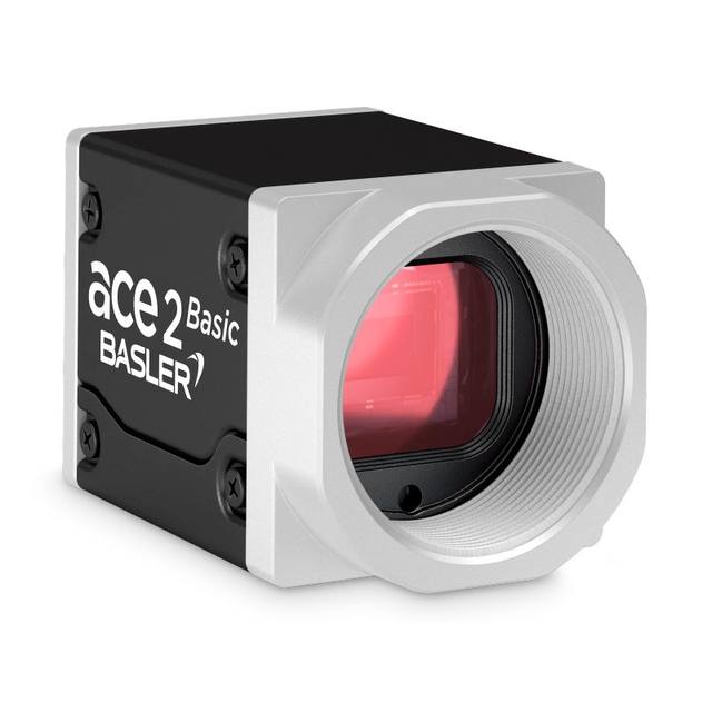
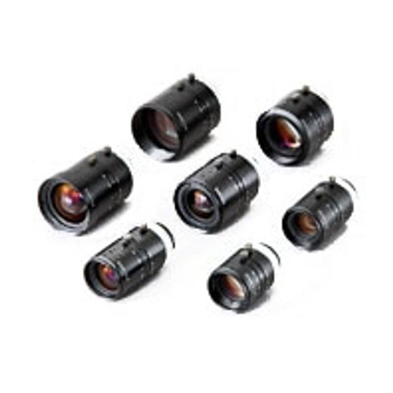
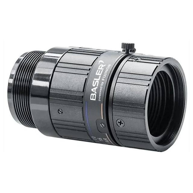
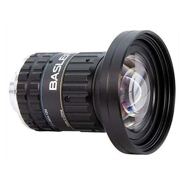
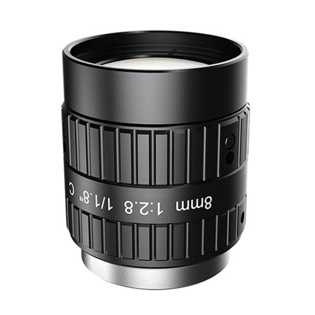
The 3Z4S-LE SV-2514H belongs to Omron's SV-H series of high-resolution, low-distortion fixed-focal lenses for 2/3-inch C-mount megapixel cameras. Its bright F1.4 maximum aperture supports high-speed CMOS image sensors. The 25mm focal length gives a narrower 15.0° (V) × 20.0° (H) field of view suited to detailed inspection tasks, with a minimum working distance of 150mm. The compact 36mm body (65g) and focus/iris lock screws make it suitable for machine-vision line installations.
The Omron 3Z4S-LE SV-2514H is a 25 mm fixed-focal-length C-mount lens engineered specifically for megapixel machine-vision cameras equipped with 2/3-inch sensors (approximately 11 mm image-circle diagonal). A 25 mm focal length sits in the moderate telephoto range for machine vision: it delivers a horizontal field of view of 20.0° and a vertical field of view of 15.0°, making it appreciably narrower than a 16 mm or 12 mm option on the same sensor. At a 300 mm working distance — a typical conveyor or in-line inspection standoff — the horizontal field covers roughly 105–110 mm, which is well suited to component-level detail, label text, and code reading rather than wide-part surveying. The minimum working distance of 150 mm sets the close-focus limit; within that constraint the lens is not the right choice for macro or close-proximity inspection without supplementary extension tubes.
The lens opens to F1.4 and stops down to F16, giving the integrator full control over both light gathering and depth of field. At F1.4 the lens admits significantly more light than at F16 — the ratio of light admitted scales with the square of the f-number ratio — which is a critical advantage on high-speed lines where exposure times must be short enough to freeze motion. Closing the aperture to F5.6–F8 is the normal practice when depth of field is the priority: parts that vary in Z-height across the field stay sharper, at the cost of needing proportionally more illumination or longer exposure. The lens is rated for 2/3-inch sensors, so it works without vignetting on any camera with a sensor diagonal at or below 11 mm. The C-mount thread is universal across virtually all compact industrial cameras, and the integrated focus and iris lock screws allow both parameters to be fixed after setup so vibration or accidental contact cannot shift the image.
Resolving power is matched to the megapixel format the lens targets. High-resolution, low-distortion SV-H series optics are designed so that the optical resolving limit does not become the system bottleneck ahead of the sensor pixel pitch — a common failure mode when standard CCTV-grade glass is paired with high-resolution sensors. Low geometric distortion is an explicit design goal of this series, which matters for dimensional measurement and OCR/OCV tasks where straight edges must remain straight across the full field. The non-telecentric design means magnification does vary with working distance (parallax error is present), so for tight dimensional tolerances the working distance must be well controlled and calibrated; telecentric lenses are the alternative when true object-space telecentricity is needed. At 65 g and 36 mm body length, the lens is compact enough for multi-camera arrays and robot-mounted inspection heads.
Best for
Fine-detail inspection on 2/3-inch megapixel cameras where the field of view is 80–200 mm wide at working distances of 200–600 mm — typical of PCB, component, label, or blister-pack inspection on a fixed conveyor.
High-speed line applications where the F1.4 maximum aperture enables very short exposures to freeze fast-moving parts without resorting to extremely intense strobe lighting.
OCR/OCV and 1D/2D code reading where the narrower 20° horizontal field concentrates pixel density on the target region and the low-distortion design keeps character and bar geometry accurate across the frame.
Dimensional measurement tasks where consistent, well-corrected optics over the full 2/3-inch sensor area are required and working distance is fixed and controlled.
Multi-camera machine-vision systems where the compact 65 g, 36 mm body and standard C-mount allow dense installation with mechanical lock screws to resist vibration-induced drift.
Selection notes
Match sensor format before purchasing: this lens covers a maximum 2/3-inch (approximately 11 mm diagonal) image circle. Cameras with sensors larger than 2/3-inch will exhibit vignetting — darker corners — which disqualifies the lens for those platforms regardless of any other parameter match.
Calculate field of view at your actual working distance before assuming the 25 mm focal length is appropriate. On a 2/3-inch sensor, 25 mm gives roughly 105–110 mm horizontal field at 300 mm distance; if your part is wider than the field or you need more spatial context, a shorter focal length (12 mm or 16 mm) is more appropriate, while very small targets requiring a larger image scale call for a longer focal length or a macro lens.
Account for depth of field when setting aperture. At F1.4 depth of field on a megapixel sensor can be just a few millimeters, which is sufficient only when part height variation is tightly controlled. If Z-height variation across the part exceeds a few millimeters, plan to use F5.6–F8 and size your lighting to compensate.
Because this is a non-telecentric lens, magnification changes with working distance — a part that is closer to the lens appears slightly larger. For measurement applications, calibrate at the nominal working distance and control Z-height variation of the part. If measurement tolerances are tight, evaluate whether a telecentric lens is required instead.
Always tighten both the focus lock screw and the iris lock screw after setup. Without locking, vibration from nearby machinery, thermal cycling, or accidental contact can shift focus or aperture during a production run, causing images to drift out of specification without any obvious alert.
Specifications: General
Brand
Omron / Sentech
Specifications: Optical
Focal length
25 mm
Lens mount
C-mount
Aperture (f-number)
F1.4–F16
Image circle / max sensor
2/3" (≈ 11 mm diagonal)
Telecentric
No
Specifications: Environment
Operating temperature
0 to 50°C
Specifications: Mechanical
Weight
65 g
Applications this camera is commonly selected for. Open one to see the full recommended hardware and approach.
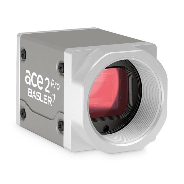
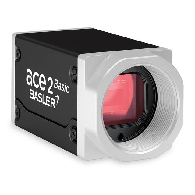
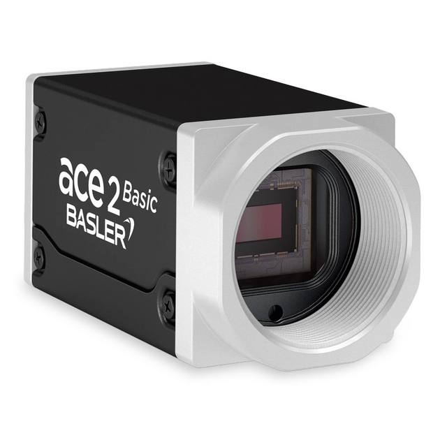
Matched automatically by: camera mount fits the lens mount · camera sensor is covered by the lens image circle — this lens: C-mount · 2/3" (≈ 11 mm diagonal) image circle.
By category
All 758Area scan cameras 622High-speed cameras 108High-resolution cameras 28
By brand
All 758Omron / Sentech 297Basler 242iRAYPLE 200Datalogic / Datasensing 19
These steps take an Omron Sentech (STC) camera from the box to a stable first image and on to your own application. They apply across the GigE Vision, USB3 Vision and CoaXPress STC families; the interface only changes how you cable and power the camera.
Download and install the Sentech SDK on the host PC. The package provides StViewer, the viewing and configuration software you use to bring the camera up, and StApi, the programming SDK you integrate later. Because the cameras are GenICam/GenTL-compliant, StApi also registers a GenTL producer, so any GenICam-compliant third-party vision software can discover and drive the camera as an alternative front end.
2. Cable, power and connect the camera
Connect according to the interface. GigE Vision: link to a Gigabit NIC (use PoE or the separate power input) and put the camera and host on the same subnet; for USB3 Vision use a USB 3.x port and a certified cable; for CoaXPress (STC) connect to a CoaXPress frame grabber, which also supplies Power-over-Coax. Then open StViewer and let it enumerate the camera. If a GigE camera does not appear, check the IP configuration and firewall, and on USB3 confirm the host bandwidth and driver.
3. Configure exposure, gain and white balance
Open the device in StViewer and start a live stream. Set exposure and gain for a well-exposed, low-noise image: raise exposure first and only add gain when more light or a faster shutter is not an option, keeping exposure short enough to freeze motion on global-shutter models. On colour cameras, run white balance under your actual production lighting. Adjust the lens aperture and focus on a representative target before tuning anything else.
4. Set the trigger and grab a first image
Start in free-run (continuous) acquisition to confirm a clean, stable image. For inline inspection switch to hardware or software triggering: select the trigger source, set the active edge and any delay, and wire the strobe or illumination to the camera's I/O so lighting fires with each exposure. Acquire and save a frame in StViewer; this saved image is your reference for the SDK stage and for downstream inspection.
5. Move to the StApi SDK (or any GenICam software)
Once the image is stable, reproduce the same settings in code. Use StApi to open the device, apply the GenICam features you validated in StViewer (exposure, gain, trigger, pixel format) and grab frames into your application via the bundled C++, C, C#/.NET or Python interfaces; the included samples are the fastest starting point. Prefer a different stack? The same GenICam/GenTL camera works with third-party vision libraries. With a reliable feed, you can route it into a deep-learning inspection such as Rosepetal for AI-based defect detection.
Frequently asked questions
At 300 mm working distance with a 2/3-inch sensor (approximately 8.8 mm × 6.6 mm active area), the 25 mm focal length yields a horizontal field of approximately 105–110 mm and a vertical field of approximately 79–82 mm. The exact figure depends on the precise active sensor dimensions of the camera selected. Use the standard FOV formula — FOV = sensor dimension × (working distance / focal length) — substituting your camera's actual sensor dimensions for a precise result.
The image circle is rated for 2/3-inch sensors (approximately 11 mm diagonal). A 1/1.8-inch sensor format is smaller than 2/3-inch and is covered. A 1-inch sensor has a larger diagonal that exceeds the image circle — vignetting will appear in the corners and the lens is not suitable for that format without accepting significant light falloff at the edges.
F1.4 is among the brightest apertures available in fixed machine-vision lenses. Compared to smaller apertures, F1.4 admits substantially more light — the amount of light admitted scales with the square of the f-number ratio — allowing proportionally shorter exposure times for the same sensor output level. This is a significant advantage on lines where motion blur must be minimized, as very short exposures can freeze fast-moving parts.
The low-distortion SV-H design makes this lens suitable for dimensional measurement. However, because it is not telecentric, magnification changes with working distance — a part that is closer to the lens appears slightly larger in the image. For measurement applications, calibrate at the nominal working distance and control Z-height variation of the part. If measurement tolerances are very tight or if parts present significant height variation, evaluate telecentric lens alternatives.
The focus lock screw fixes the focus ring in place once the lens is focused at the intended working distance, and the iris lock screw fixes the aperture. In production installations both should always be tightened after setup. Without locking, vibration from nearby machinery, thermal cycling, or accidental contact can shift focus or aperture during a production run, causing images to drift out of specification without any obvious alert — a subtle failure mode that can go undetected until yield metrics degrade.