Omron / Sentech E3Z-LL Series (Laser BGS Distance-Settable Photoelectric Sensor)
E3Z-LL61
The Omron E3Z-LL is a compact diffuse background-suppression (BGS, distance-settable) laser photoelectric sensor using a 655 nm red laser diode (JIS Class 1 / IEC Class 1 / FDA Class 2) with a 0.5 mm spot at 300 mm, detecting white paper from 20-300 mm (LL61/66/81/86) or 25-300 mm (LL63/68/83/88). Standard-response models (LL61/66/81/86) have a 1 ms response time while high-speed models (LL63/68/83/88) reach 0.5 ms. It runs on 12-24 VDC (30 mA max) and provides a 100 mA max open-collector output, NPN on LL61/63/66/68 and PNP on LL81/83/86/88, with switch-selectable light-ON/dark-ON operation. The IP67 PBT housing operates from -10 to 55 C, connecting via a 2 m pre-wired cable (LL61/63/81/83) or M8 connector (LL66/68/86/88).
The Omron E3Z-LL is a diffuse photoelectric sensor that works on the background-suppression (BGS, distance-settable) principle, which means it triggers on the distance to the target rather than on the amount of returned light. Instead of a simple intensity threshold, the sensor uses optical triangulation to detect where the reflection lands and switches when an object enters a set distance window, ignoring whatever sits behind it. That distinction matters in practice: a standard diffuse sensor can be fooled by a dark, matte part close up versus a bright, glossy background farther away, while a BGS sensor like this one keys on geometry, so it reliably separates a part from a conveyor belt, a fixture, or a wall behind it regardless of surface color or finish. The light source is a 655 nm red laser diode (rated JIS Class 1 / IEC Class 1 / FDA Class 2) that focuses to a 0.5 mm spot at 300 mm, giving it the small, well-defined beam needed to catch thin edges, small features, and tiny parts that a wider LED diffuse spot would miss.
Sensing range is specified to 300 mm against white paper, with a near limit of 20 mm on the standard-response models (LL61/66/81/86) or 25 mm on the high-speed models (LL63/68/83/88); because it is a BGS device, the actual switch point is set within that window rather than being a fixed maximum. Response time is the other axis of model choice: standard models switch in 1 ms max, while the high-speed variants reach 0.5 ms max, which on a fast line translates directly into how small a part the sensor can resolve at a given belt speed. Electrically it is a self-contained sensor with a built-in amplifier, running on 12-24 VDC (+/-10%) at 30 mA max and driving a 100 mA max open-collector output. Output polarity is fixed by part number, NPN on LL61/63/66/68 and PNP on LL81/83/86/88, and each model offers switch-selectable light-ON / dark-ON operation so the active state can be matched to whether part-present or part-absent should assert the line.
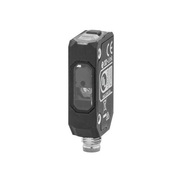
Mechanically the sensor is built for in-line machine use: a compact PBT housing measuring approximately 10.8 x 31 x 20 mm with a modified-polyarylate lens, rated IP67 to IEC 60529 and specified from -10 to 55 C operating. Connection is split by suffix, with pre-wired 2 m cable versions (LL61/63/81/83) and M8 connector versions (LL66/68/86/88) for tool-less swaps in serviced cells. As a discrete sensor it integrates as a trigger or presence signal rather than a measurement-bus device: you wire its single switching output into a PLC input, a camera trigger, or a reject gate. Pairing it with a vision system, it is well suited to providing a clean, repeatable position-based trigger pulse the instant a part crosses the set distance plane, decoupling the camera from belt-color and reflectivity variation that would otherwise make a light-intensity trigger unreliable.
Best for
Position triggering for vision inspection, firing a camera the moment a part crosses a set distance plane regardless of belt color or surface gloss
High-precision part presence and edge detection where a fine 0.5 mm laser spot is needed to catch small features or thin objects
Background-suppression sorting on logistics and packaging lines, separating parts from conveyors and fixtures behind them within the 20-300 mm window
Small-part detection and positioning on fast lines using the 0.5 ms high-speed models (LL63/68/83/88) for tighter timing resolution
Robot-guidance and dimensional-check tasks needing a stable distance-based switch point that ignores reflectivity changes
Selection notes
Pick the response-time class deliberately: standard models (LL61/66/81/86) switch in 1 ms with a 20-300 mm window, while high-speed models (LL63/68/83/88) reach 0.5 ms but start at 25 mm; faster response resolves smaller parts at a given line speed.
Output polarity is set by part number and cannot be changed in the field: NPN on LL61/63/66/68 and PNP on LL81/83/86/88, so match it to your PLC or trigger input before ordering.
Choose the connection style by serviceability: pre-wired 2 m cable (LL61/63/81/83) for fixed installs versus M8 connector (LL66/68/86/88) for tool-less replacement in maintained cells.
Because range is specified against white paper, very dark or specular targets will shift the usable window; set the BGS switch distance on the actual part and verify margin within the 20-300 mm (or 25-300 mm) span.
Confirm the environment fits the IP67 rating and -10 to 55 C operating range, and budget the 30 mA supply draw and 100 mA output load against your 12-24 VDC source.
Specifications: General
Brand
Omron / Sentech
Sensor type
Photoelectric (diffuse laser BGS)
Specifications: Performance
Range / distance
20-300 mm (white paper; LL61/66/81/86); 25-300 mm (LL63/68/83/88)
Response time
1 ms max (LL61/66/81/86); 0.5 ms max (LL63/68/83/88)
Specifications: Interface
Connection
Pre-wired cable 2 m (LL61/63/81/83) or M8 connector (LL66/68/86/88)
These steps take an Omron Sentech (STC) camera from the box to a stable first image and on to your own application. They apply across the GigE Vision, USB3 Vision and CoaXPress STC families; the interface only changes how you cable and power the camera.
Download and install the Sentech SDK on the host PC. The package provides StViewer, the viewing and configuration software you use to bring the camera up, and StApi, the programming SDK you integrate later. Because the cameras are GenICam/GenTL-compliant, StApi also registers a GenTL producer, so any GenICam-compliant third-party vision software can discover and drive the camera as an alternative front end.
2. Cable, power and connect the camera
Connect according to the interface. GigE Vision: link to a Gigabit NIC (use PoE or the separate power input) and put the camera and host on the same subnet; for USB3 Vision use a USB 3.x port and a certified cable; for CoaXPress (STC) connect to a CoaXPress frame grabber, which also supplies Power-over-Coax. Then open StViewer and let it enumerate the camera. If a GigE camera does not appear, check the IP configuration and firewall, and on USB3 confirm the host bandwidth and driver.
3. Configure exposure, gain and white balance
Open the device in StViewer and start a live stream. Set exposure and gain for a well-exposed, low-noise image: raise exposure first and only add gain when more light or a faster shutter is not an option, keeping exposure short enough to freeze motion on global-shutter models. On colour cameras, run white balance under your actual production lighting. Adjust the lens aperture and focus on a representative target before tuning anything else.
4. Set the trigger and grab a first image
Start in free-run (continuous) acquisition to confirm a clean, stable image. For inline inspection switch to hardware or software triggering: select the trigger source, set the active edge and any delay, and wire the strobe or illumination to the camera's I/O so lighting fires with each exposure. Acquire and save a frame in StViewer; this saved image is your reference for the SDK stage and for downstream inspection.
5. Move to the StApi SDK (or any GenICam software)
Once the image is stable, reproduce the same settings in code. Use StApi to open the device, apply the GenICam features you validated in StViewer (exposure, gain, trigger, pixel format) and grab frames into your application via the bundled C++, C, C#/.NET or Python interfaces; the included samples are the fastest starting point. Prefer a different stack? The same GenICam/GenTL camera works with third-party vision libraries. With a reliable feed, you can route it into a deep-learning inspection such as Rosepetal for AI-based defect detection.
Frequently asked questions
It is a discrete switching sensor, not an analog measurement device. It uses background suppression to switch a 100 mA max open-collector output on or off when a target enters a set distance window within 20-300 mm (25-300 mm on high-speed models). It provides a trigger or present/absent signal, not a continuous distance value.
Sensing range is specified to 300 mm against white paper, with a near limit of 20 mm on standard models (LL61/66/81/86) or 25 mm on high-speed models (LL63/68/83/88). The 655 nm red laser focuses to a 0.5 mm spot at 300 mm, fine enough to detect small parts and thin edges.
Yes. Output polarity is fixed by part number: LL61/63/66/68 are NPN and LL81/83/86/88 are PNP. All variants provide a 100 mA max open-collector output with switch-selectable light-ON / dark-ON operation.
Standard-response models (LL61/66/81/86) have a 1 ms max response time, and high-speed models (LL63/68/83/88) reach 0.5 ms max. The faster models let you resolve smaller or more closely spaced parts on fast-moving lines.
It runs on 12-24 VDC (+/-10%) at 30 mA max and drives a 100 mA max open-collector output. Connection is either a pre-wired 2 m cable (LL61/63/81/83) or an M8 connector (LL66/68/86/88). The housing is PBT, rated IP67, and operates from -10 to 55 C.
Background suppression switches on distance rather than returned-light intensity, so it reliably separates a target from the conveyor, fixture, or wall behind it even when surface color or gloss varies. That makes it far more stable than a standard diffuse sensor for triggering and presence detection on mixed or shiny parts.

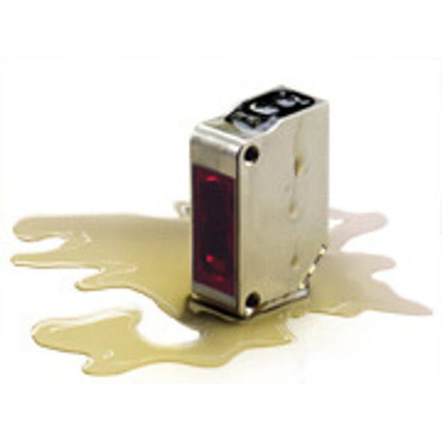 Omron / SentechOmron / Sentech E3ZM-C Oil-Resistant Compact Stainless-Steel Photoelectric SensorE3ZM-C