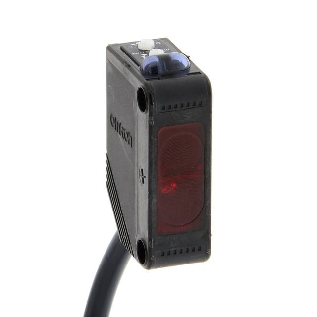
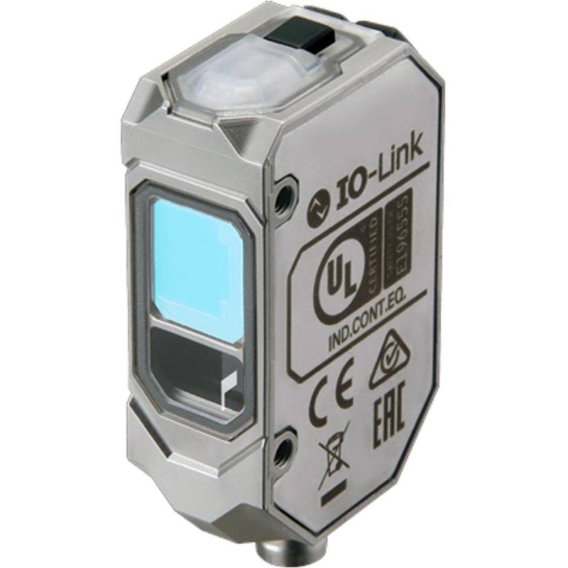
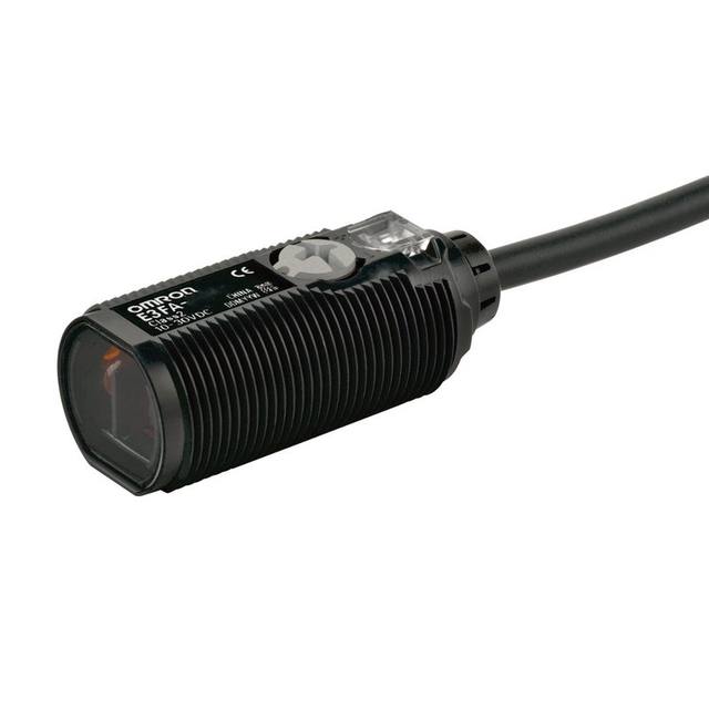
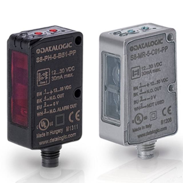
The E3AS-HL500MT-M3J is a distance-settable (background-suppression) photoelectric sensor using a Class 1 red laser diode and a CMOS receiver with a 2.5 x 1.5 mm spot beam, giving a 35-500 mm sensing range. It has a response time of 1.5 ms, 10-30 VDC supply, PNP output with IO-Link COM3 (230.4 kbps), and Light-ON/Dark-ON selection. The stainless-steel housing is rated IP67/IP67G/IP69K and terminates in a 4-pin M8 pigtail connector with a 0.3 m cable.
The E3AS-HL500MT-M3J is a distance-settable photoelectric sensor, which means it does not simply detect whether light is returned but where the light is returned from. It works on the background-suppression principle: a Class 1 red laser diode at 660 nm projects a small 2.5 x 1.5 mm spot onto the target, and a CMOS receiver reads the lateral position of the reflected spot by triangulation. Because the decision is based on the angle of the returned beam rather than its intensity, the sensor switches on a target inside a set distance and ignores anything beyond it, regardless of how shiny, dark, or reflective the background is. The teachable range runs from 35 mm to 500 mm against white paper, so you set a threshold distance and the sensor reports whether an object is nearer than that plane. The tight laser spot lets it resolve small parts, edges, and narrow features that a diffuse LED sensor would smear over.
Electrically the sensor is straightforward to design in. It runs on a wide 10-30 VDC supply and provides a PNP switching output with selectable Light-ON / Dark-ON polarity, so the same part can report either presence or absence without rewiring. The standout interface is IO-Link COM3 at 230.4 kbps: connected to an IO-Link master, the device exchanges its status digitally and accepts remote teaching and parameter setting, which removes manual potentiometer drift and lets you store and clone configurations across a line. With a 1.5 ms response time it is fast enough to gate a vision capture or confirm part-in-position on a moving indexer; wired to a camera it makes a clean position-referenced trigger, and over IO-Link it integrates cleanly with the controller for remote setup and monitoring.
For the physical environment this is a hardened part. The housing is stainless steel and carries IP67, IP67G, and IP69K ratings, so it tolerates washdown, high-pressure hot-water cleaning, and the splash and coolant typical of automotive and packaging cells. The compact 15.5 x 48.6 x 30.4 mm body terminates in a 4-pin M8 pigtail with a 0.3 m cable, suiting tight fixtures and robot end-of-arm mounts where a full barrel sensor would not fit. As a Class 1 laser product it is eye-safe in normal use and needs no interlock enclosure. In a vision system it typically sits alongside the camera as a trigger or a distance reference rather than as the imaging device itself, handing a reliable presence/position signal to the camera and the PLC.
Best for
Triggering a camera or confirming part-in-position on automotive assembly lines, where the stainless IP69K housing survives washdown and coolant splash around the cell
Robot-guidance and end-of-arm pick confirmation, using the compact M8 body and 35-500 mm distance teach to verify a part is present at the gripper before the next move
Dimensional and presence checks on small electronics components, where the 2.5 x 1.5 mm laser spot resolves narrow edges and parts a diffuse LED sensor would miss
Detecting flat, low-contrast, or dark targets against a reflective background on packaging machinery, since background suppression decides on distance rather than returned light intensity
Line-wide deployment over IO-Link, where the COM3 interface lets the controller remotely teach, configure, store, and monitor sensor settings across many stations
Selection notes
Confirm your target sits within the 35-500 mm teach window; the published range is referenced to white paper, so very dark or specular surfaces effectively shorten the reliable detection distance and should be tested at the working plane.
To use remote teaching and parameter setting you need an IO-Link master and a COM3-capable port; without one the device still works as a plain PNP switch with Light-ON/Dark-ON selection, but you lose the digital configuration and parameter-cloning benefits.
Plan the wiring around the 4-pin M8 pigtail with only a 0.3 m cable lead; budget for an M8 extension or junction to reach the cabinet, and route the PNP output to a PLC input or a hardware camera trigger.
Verify the 1.5 ms response time is fast enough for your line speed and indexer dwell; for higher-frequency triggering or sub-millimetre profiling, a dedicated laser displacement sensor may be the better fit than this distance-settable switch.
Match the mounting to the small spot and triangulation geometry: keep the laser roughly normal to the surface and clear of the receiver's line of sight, and use the stainless IP67G/IP69K rating to justify it in washdown zones where standard-housing sensors would corrode.
Specifications: General
Brand
Omron / Sentech
Sensor type
Photoelectric (distance-settable CMOS laser)
Specifications: Performance
Range / distance
35-500 mm (white paper)
Response time
1.5 ms
Specifications: Interface
Communication
IO-Link COM3 (230.4 kbps)
Connection
M8 connector
Specifications: Electrical
Supply voltage
10-30 VDC
Specifications: Environment
IP rating
IP67 / IP67G / IP69K
Specifications: Mechanical
Housing material
Stainless steel
Dimensions
15.5 x 48.6 x 30.4 mm
Specifications: Sensing
Sensing method
Background suppression
Light source
Red laser diode, 660 nm, Class 1
Specifications: Output
Output type
IO-Link / PNP
Applications this camera is commonly selected for. Open one to see the full recommended hardware and approach.
These steps take an Omron Sentech (STC) camera from the box to a stable first image and on to your own application. They apply across the GigE Vision, USB3 Vision and CoaXPress STC families; the interface only changes how you cable and power the camera.
Download and install the Sentech SDK on the host PC. The package provides StViewer, the viewing and configuration software you use to bring the camera up, and StApi, the programming SDK you integrate later. Because the cameras are GenICam/GenTL-compliant, StApi also registers a GenTL producer, so any GenICam-compliant third-party vision software can discover and drive the camera as an alternative front end.
2. Cable, power and connect the camera
Connect according to the interface. GigE Vision: link to a Gigabit NIC (use PoE or the separate power input) and put the camera and host on the same subnet; for USB3 Vision use a USB 3.x port and a certified cable; for CoaXPress (STC) connect to a CoaXPress frame grabber, which also supplies Power-over-Coax. Then open StViewer and let it enumerate the camera. If a GigE camera does not appear, check the IP configuration and firewall, and on USB3 confirm the host bandwidth and driver.
3. Configure exposure, gain and white balance
Open the device in StViewer and start a live stream. Set exposure and gain for a well-exposed, low-noise image: raise exposure first and only add gain when more light or a faster shutter is not an option, keeping exposure short enough to freeze motion on global-shutter models. On colour cameras, run white balance under your actual production lighting. Adjust the lens aperture and focus on a representative target before tuning anything else.
4. Set the trigger and grab a first image
Start in free-run (continuous) acquisition to confirm a clean, stable image. For inline inspection switch to hardware or software triggering: select the trigger source, set the active edge and any delay, and wire the strobe or illumination to the camera's I/O so lighting fires with each exposure. Acquire and save a frame in StViewer; this saved image is your reference for the SDK stage and for downstream inspection.
5. Move to the StApi SDK (or any GenICam software)
Once the image is stable, reproduce the same settings in code. Use StApi to open the device, apply the GenICam features you validated in StViewer (exposure, gain, trigger, pixel format) and grab frames into your application via the bundled C++, C, C#/.NET or Python interfaces; the included samples are the fastest starting point. Prefer a different stack? The same GenICam/GenTL camera works with third-party vision libraries. With a reliable feed, you can route it into a deep-learning inspection such as Rosepetal for AI-based defect detection.
Frequently asked questions
The sensor uses triangulation: the CMOS receiver reads the position of the reflected laser spot to judge distance, not just brightness. You teach a threshold distance anywhere from 35 to 500 mm, and it switches only on targets nearer than that plane, ignoring the background no matter how reflective or dark it is.
Yes, over IO-Link. The device supports IO-Link COM3 at 230.4 kbps, which carries its status digitally and allows remote teaching and parameter setting, so you can configure, store, and clone settings from the controller. Connected only as a discrete output it provides a PNP on/off switching signal.
It uses a 660 nm red laser diode classified as Class 1, which is eye-safe under normal operating conditions, so it does not require a laser interlock enclosure for routine use.
It is built for it. The housing is stainless steel and rated IP67, IP67G, and IP69K, so it withstands dust, immersion-grade splash, and high-pressure high-temperature washdown cleaning.
It runs on 10-30 VDC and provides a PNP output with selectable Light-ON or Dark-ON. With a 1.5 ms response time you can wire the PNP output straight into a PLC input or a camera trigger line via the 4-pin M8 connector to gate image capture on part arrival.